Kesavansona (talk | contribs) |
Kesavansona (talk | contribs) |
||
| Line 1: | Line 1: | ||
| − | [[Media: | + | [[Media:Review_657359173847_3026_Revised paper-1.docx|Revised paper-1.docx]] |
<!-- metadata commented in wiki content | <!-- metadata commented in wiki content | ||
Revision as of 09:12, 29 November 2022
Abstract: To engage in the power market throughout the deregulation process, the entire electrical market is divided into GENCOS, TRANSCOS, and DISCOS. Each firm focuses on delivering their best output. This lead to Congestion issues on transmission lines. As there is not enough transmission capability to satisfy the load demand, transmission congestion occurs. Transmission cable congestion results from a lack of coordination between the utilities that handle generating, transmission, and distribution. This can lead to generator failure, an abrupt increase in load demand, or the miscarriage of equipment, all of which can be fixed by FACTS devices. In this work, transmission line congestion is reduced using FACTS devices like UPFC and IPFC. The primary goal is to determine where FACTS devices should be placed. The main goal is to use the ANTLION optimization algorithm to locate the optimal position and size for FACTS devices. In an IEEE-14 bus system, UPFC and IPFC are individually connected, and their important parameters are analyzed.
Keywords: UPFC; IPFC; Congestion; IEEE-14 bus system; ANTLION optimization.
1. INTRODUCTION
Transmission line losses are due to the extreme loads, lack of co-ordination between generation, transmission and loads. There will be a loss of ability to retain power in the system as a result of an increase in distribution-side load and decreased power generation as discussed in paper [1]. Further the proposed work establishes the goal of the study and identifies the characteristics of the system with and without FACTS devices identified in [2, 3]. FACTS device play a major role to reduce power losses and improve the network's efficiency in order to minimize power loss [4]. Different techniques have been discussed [5] to reduce power losses and maintain power quality; the most efficient topology and compact system method is used. The transmission line connects FACTS devices like the UPFC and IPFC. A comparison of UPFC and IPFC analyzed [6, 7] and utilized to make up for the system's lagging output voltage by computing the difference between the reference voltage and output voltage. By using the FACTS device, the voltage difference is injected. An optimization technique called Antlion is used to determine the required size of the FACTS device as proposed in [8, 9]. To obtain better power fed load as objective for FACTS device the proposed work algorithm analyzed the system with a FACTS device and the system without a FACTS device, an IEEE-14 bus test system is used to develop the model and presented for work.
2. MATERIAL AND METHODS
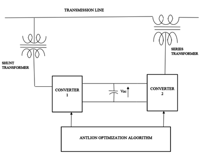
One of the FACTS components, the unified power flow controller (UPFC), is connected in both a shunt and series form. Two back-to-back converters are included in the UPFC, converters 1 and 2, which are connected by a typical dc coupling provided by a dc storage capacitor. According to this theory, actual power can flow between the ac terminals of the two converters in any direction, and each converter can independently generate or absorb reactive power at its own ac output terminal. When a voltage sag or swell occurs in the transmission line, UPFC absorbs or generates reactive power to help maintain a constant output voltage. Converters 1 and 2 are coupled to the transmission line in series and shunt, respectively. ANTLION optimization algorithm is used to determine the optimal size and position of UPFC. The proposed block diagram of UPFC is shown below figure 1.
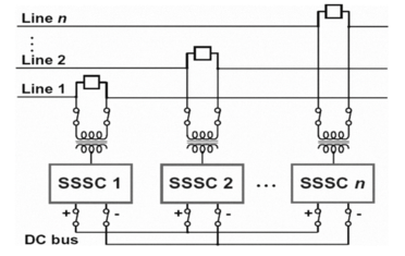
One of the FACTS devices, the Interline Power Flow Controller (IPFC), is used to regulate the power flow of several transmission lines. The device IPFC, which is derived from UPFC, contains n converters that regulate the power flow between the lines; the minimum number of converters that must be connected back to back is two. To manage the power flow, each converter must be connected in series with a distinct transmission line. In order to maintain control over the DC link voltage during this operation, active power must be coordinated. Each converter's reactive power is independent; the DC link voltage is achieved by similar way as UPFC. One series converter can produce an active power flow flowing into the link and can control voltage freely. The remaining n number of transmission lines transfer active power from one line to another to balance the power flow in the n parallel transmission lines if there are n number of converters and (n-1) converters can absorb or generate active power while one converter must control the DC link voltage. The ANTLION optimization algorithm is used to determine the optimal size and position of IPFC. The proposed block diagram of IPFC is shown below figure 2.
The majority of problems require precise values and strong tools for computing those values. Various methods are utilized for problem solving, and the ANTLION'S hunting skill aids in pinpointing the food. To search ants, ant lion makes use of the upcoming process
Y(t) = [0, cumulative sum(2r(t1) – 1), cumulative sum(2r(t2) – 1), . . . , cumulative sum(2r(tn) – 1),]
| r(t) = | (1) |
The location of ants is stored in matrix with the proportional value of each ANTLION is determined and kept in the matrices:
3. EXECUTION OF ANT LION OPTIMIZATION ALGORITHM IN THE PROPOSED SYSTEM
• Step 1: Simulate the IEEE-14 bus test system and run the Simulink model without implementing FACTS device.
• Step 2: Analyse the active power, reactive power, input voltage, output voltage characteristics through scope without FACTS device for 100% load.
• Step 3: Increase the load moderately by 25% then the 100% original load and analyse the active power, reactive power, input voltage, output voltage characteristics.
• Step 4: Constantly increase the load moderately by 25% than the 125% of previous load and analyse the active power, reactive power, input voltage, output voltage characteristics.
• Step 5: Constantly increase the load moderately by 25% than the 150% of previous load and analyse the active power, reactive power, input voltage, output voltage characteristics.
• Step 6: Differentiate the voltage difference for the 100% load, 125% load, 150% load, 175% load and find the disturbances in active and reactive power.
• Step 7: Design the IEEE-14 bus test system with UPFC.
• Step 8: Switch on the UPFC in the transmission line and apply the antlion algorithm in the simulation.
• Step 9: Repeat the step 2 to step 6.
• Step 10: The lagging voltage is improved by generating reactive power for the corresponding change in the load by using UPFC, the output voltage is improved nearly to the input voltage, the deviations in the real and reactive power characteristics are also improved for the corresponding change in the consecutive loads.
• Step 11: Design the IEEE-14 bus test system with IPFC.
• Step 12: Switch on the IPFC in the transmission line and apply the antlion algorithm in the simulation.
• Step 13: Repeat the step 2 to step 6.
• Step 14: The lagging voltage is improved by generating reactive power for the corresponding change in the load by using IPFC, the output voltage is improved nearly to the input voltage, the deviations in the real and reactive power characteristics are also improved for the corresponding change in the consecutive loads
• Step 15: Compare the output voltage, real power, reactive power and voltage injected by UPFC and IPFC and find the best FACTS device which is suitable for the operation.
4. RESULTS AND DISCUSSION
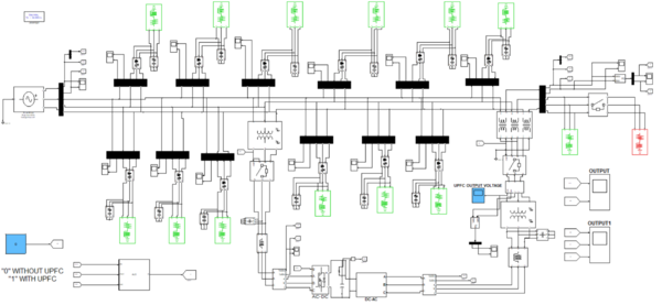
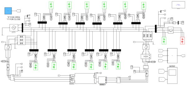
In this work, the IEEE-14 bus test system is designed and analyzed using MATLAB & Simulink models shown in figure 3 represent the proposed system. The system is connected along with UPFC and an additional switch is provided to know the characteristics of the system without IPFC and with IPFC. To turn on IPFC, 1 is given to run the system with IPFC and 0 is given, IPFC is in off state and run the system without IPFC. One generating bus is given and thirteen load buses are designed in this simulation.
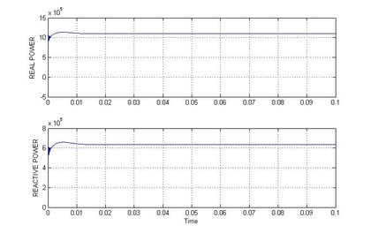
In figure 4 shows the real and reactive power of the proposed system without UPFC, there is no constant output is monitored and there are deviations in curves less than 0.05 seconds, and the proposed system, run with the base load of 10MW and we can see that the output voltage is lagging than the permissible voltage variation.
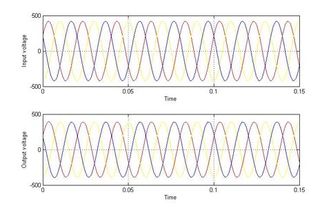
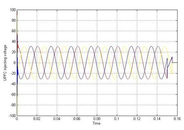
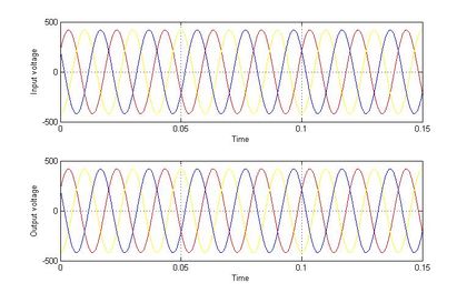
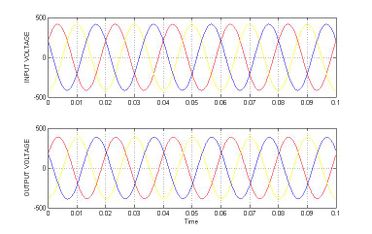
In the figure.5 shows the lagging voltage is injected by UPFC, the algorithm monitors the input and output voltage and the voltage difference between the recommended voltage and the output voltage is monitored and according to the voltage difference, the UPFC inject voltage to compensate the lagging voltage, and in figure 6 shows the real and reactive power deviations are minimized, compared to the system without UPFC and holds better the input and output voltage is compensated using UPFC and output voltage is improved nearer to input voltage.
| LOAD IN PERCENTAGE | OUTPUT LOAD IN MW | INPUT VOLTAGE
(VOLTS) |
OUTPUT VOLTAGE
(VOLTS) |
LAGGING VOLTAGE
(VOLTS) |
OUTPUT VOLTAGE AFTER PLACING UPFC
(VOLTS) |
| 100 | 10 | 415 | 385 | 30 | 415 |
| 125 | 12.5 | 415 | 376 | 39 | 415 |
| 150 | 15 | 415 | 370 | 45 | 415 |
| 175 | 17.5 | 415 | 360 | 55 | 415 |
The table 1 contains the values of graphs that are obtained while the system works with UPFC and without UPFC. In figure.7 shows the real and reactive power of the proposed system without IPFC, there is no constant output is monitored and there are deviations in curves less than 0.05 seconds, and in figure 8 shows the proposed system, run with the base load of 10MW and we can see that the output voltage is lagging than the permissible voltage variation.
| LOAD IN PERCENTAGE | OUTPUT LOAD IN MW | INPUT VOLTAGE
(VOLTS) |
OUTPUT VOLTAGE
(VOLTS) |
LAGGING VOLTAGE
(VOLTS) |
OUTPUT VOLTAGE AFTER PLACING IPFC
(VOLTS) |
| 100 | 10 | 415 | 384 | 31 | 415 |
| 125 | 12.5 | 415 | 376 | 39 | 415 |
| 150 | 15 | 415 | 369 | 46 | 415 |
| 175 | 17.5 | 415 | 361 | 54 | 415 |
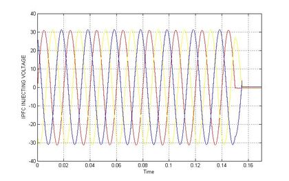
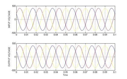
The table 2 contains the value of graphs that are obtained while the system works with IPFC and without IPFC. Figure 9 shows the lagging voltage is injected by IPFC, the algorithm monitors the input and output voltage and the voltage difference between the recommended voltage and the output voltage is monitored and according to the voltage difference, the IPFC inject voltage to compensate the lagging voltage, and in figure 10 shows the real and reactive power deviations are minimized, compared to the system without IPFC and in figure 11 shows the input and output voltage is compensated using IPFC and output voltage is improved nearer to input voltage.
5. CONCLUSION
In this work, congestion management was done by using FACTS device. The IEEE-14 Bus test system has been designed in MATLAB/Simulink and it is simulated with the system connected with FACTS device and without FACTS device. Simulation results show the FACTS device effectiveness by injecting the required voltage need by the system to maintain balance output voltage and it is found that the active and reactive power is also improved when FACTS device is introduced. The optimal allocation of FACTS device is done by using ALO algorithm. Moreover, UPFC and IPFC inject the required amount of voltage to maintain the system output voltage at constant. During the voltage injection, whereas IPFC injects only the required amount of voltage to the load but UPFC injects high voltage at the initial stage. To protect the system from damage, occur due to high voltage. The system needs to add protection circuit, which adds on additional cost on the system. This main of this work is to reduce cost and to increase the efficiency of the system. So, IPFC is comparatively better than UPFC to improve the efficiency of the system.
REFERENCES
- 1. Kumar M, Renuga P. Application of UPFC for enhancement of voltage profile and minimization of losses using Fast Voltage Stability Index (FVSI). Archives of Electrical Engineering. 2012 Jun 1;61(2):239–50.
- 2. Arun Kumar S, Padma S, Madhubalan S. Distribution Network Reconfiguration Using Hybrid Optimization Technique. Intelligent Automation & Soft Computing. 2022;33(2):777–89.
- 3. Sharma O. Power System Oscillation Damping and Stability Enhancement using Static Synchronous Series Compensator (SSSC). International Journal for Research in Applied Science and Engineering Technology. 2020 Jul 31;8(7):1818–28.
- 4. Vishnu Charan T, Parimi AΜ, Karri C. Installation cost estimation of IPFC for Power Loss Reduction in Transmission lines using Firefly Algorithm. WSEAS TRANSACTIONS ON POWER SYSTEMS. 2020 Dec 7;15:206–13.
- 5. Verma Y pal, Sharma AK. Congestion management solution under secure bilateral transactions in hybrid electricity market for hydro-thermal combination. International Journal of Electrical Power & Energy Systems. 2015 Jan;64:398–407.
- 6. Mirjalili S. The Ant Lion Optimizer. Advances in Engineering Software. 2015 May;83:80–98.
- 7. Thakre MP, Ahmad A. Interline Power Flow Controller (IPFC) Deployment in Long Transmission Lines and its Effects on Distance Relay. Journal of The Institution of Engineers (India): Series B. 2021 Aug 3;103(2):491–505.
- 8. Verma S, Saha S, Mukherjee V. Optimal rescheduling of real power generation for congestion management using teaching-learning-based optimization algorithm. Journal of Electrical Systems and Information Technology. 2018 Dec;5(3):889–907.
- 9. Hassan SKA, Tuaimah FM. Optimal location of unified power flow controller genetic algorithm based. International Journal of Power Electronics and Drive Systems (IJPEDS). 2020 Jun 1;11(2):886
Document information
Published on 20/06/23
Accepted on 10/06/23
Submitted on 03/10/22
Volume 39, Issue 2, 2023
DOI: 10.23967/j.rimni.2023.06.003
Licence: CC BY-NC-SA license
Share this document
claim authorship
Are you one of the authors of this document?
