(Created page with "== Abstract == During the manufacturing process of a carbon fiber (CFRP) part in the aircraft industry defects occur. These defects are identified through inspections carried...") |
|||
| (3 intermediate revisions by 2 users not shown) | |||
| Line 1: | Line 1: | ||
| − | == | + | <span id="_GoBack"></span> |
| + | ==1 Introduction == | ||
| − | + | ZAero Project is framed within the program of aid to research and innovation of the European Union H2020 [<span id="fn-"></span>([[#fnc-|<sup></sup>]]) ]. | |
| − | + | ||
| − | + | ||
| − | == | + | The consortium consists of the following partners: PROFACTOR, DASSAULT SYSTÈMES SE, MTORRES sistemas industriales, DANOBAT, IK4-IDEKO, AIRBUS DEFENSE&SPACE GmbH and FIDAMC. |
| − | < | + | |
| + | The aim of ZAero “Zero defect manufacturing of composite parts in the aerospace industry” project is the development of inline quality control methods for carbon fibre parts production (CFRP) to achieve: | ||
| + | |||
| + | :* Inline quality controled by: | ||
| + | |||
| + | ::* Increased productivity flexibility. | ||
| + | |||
| + | ::* Higher production rated by 15%. | ||
| + | |||
| + | ::* Avoiding productivity losses due to in-situ manual inspection work. | ||
| + | |||
| + | :* Reduction of manual in-situ inspection processes during lay-up, after infusion and curing and end-of-line rework in order to reduce production cost by 15-20%. | ||
| + | |||
| + | :* Earlier re-work processes, inline monitoring and process control to reduce waste and scrap by 50%. | ||
| + | |||
| + | ==2 ZAero control system== | ||
| + | |||
| + | The ZAero system provides an inline and automatic system to detect defects during the manufacturing through sensors. The objective of the control system with sensors is to reach TRL 6-7 during the manufacturing trials at FIDAMC. | ||
| + | |||
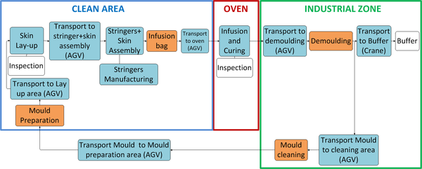
| + | The control is performed during the manufacturing process of a stiffened surface panel: | ||
| + | |||
| + | <div class="center" style="width: auto; margin-left: auto; margin-right: auto;"> | ||
| + | [[Image:Rodriguez_et_al_2018b-image5.png|600px]] </div> | ||
| + | |||
| + | <div class="center" style="width: auto; margin-left: auto; margin-right: auto;"> | ||
| + | <span style="text-align: center; font-size: 75%;">'''Figure 1.''' Process Flow Chart.</span></div> | ||
| + | |||
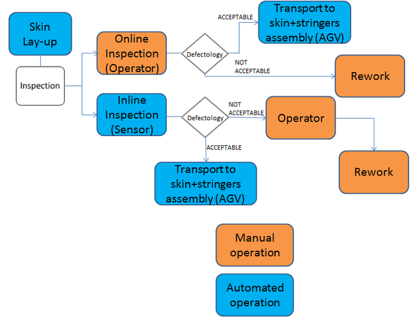
| + | The ZAero control system acts on 2 steps of the manufacturing processes: Lay-up and infusion-curing. | ||
| + | |||
| + | :* In the case of lay-up every layer is automatically inspected inline by ZAero sensors. | ||
| + | |||
| + | <div class="center" style="width: auto; margin-left: auto; margin-right: auto;"> | ||
| + | [[Image:Rodriguez_et_al_2018b-image6.png|600px]] </div> | ||
| + | |||
| + | <div class="center" style="width: auto; margin-left: auto; margin-right: auto;"> | ||
| + | <span style="text-align: center; font-size: 75%;">'''Figure 2.''' Current working method (orange) and ZAero method (blue).</span></div> | ||
| + | |||
| + | The inline inspection that will perform the control system is shown in the Figure 3. | ||
| + | |||
| + | <div class="center" style="width: auto; margin-left: auto; margin-right: auto;"> | ||
| + | [[Image:Rodriguez_et_al_2018b-image7.png|600px]] <span style="text-align: center; font-size: 75%;">'''Figure 3.''' Steps in System control process</span></div> | ||
| + | |||
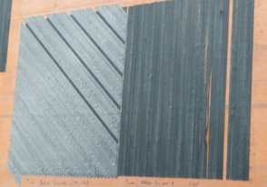
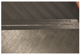
| + | Operators will inspect and act only when the error is detected by sensors. Several defects can be detected as angle deviation; late add, early cut and early add, late cut; missing tow; splices; gaps and overlaps; twist-DFP; fuzzball; defects in z-direction. | ||
| + | |||
| + | <div class="center" style="width: auto; margin-left: auto; margin-right: auto;"> | ||
| + | |||
| + | {| | ||
| + | |- | ||
| + | | [[Image:Rodriguez_et_al_2018b-image8-c.png|294px]] | ||
| + | | [[Image:Rodriguez_et_al_2018b-image9-c.png|center|294px]] | ||
| + | |} | ||
| + | </div> | ||
| + | |||
| + | <div class="center" style="width: auto; margin-left: auto; margin-right: auto;"> | ||
| + | |||
| + | {| | ||
| + | |- | ||
| + | | [[Image:Rodriguez_et_al_2018b-image10-c.png|174px]] | ||
| + | | [[Image:Rodriguez_et_al_2018b-image11.png|center|276px]] | ||
| + | |} | ||
| + | </div> | ||
| + | |||
| + | <div class="center" style="width: auto; margin-left: auto; margin-right: auto;"> | ||
| + | <span style="text-align: center; font-size: 75%;">'''Figure 4.''' Defects in Lay-up process: upper left) Gaps; upper right) Missing tow; bottom left) Butt Splice; bottom right) Twist in machine.</span></div> | ||
| + | |||
| + | The control system has two sensors: | ||
| + | |||
| + | :* Fscan: Sensor technology that uses a specific laser profile scanner to acquire 3D profiles during the AFP process. | ||
| + | |||
| + | :* Lscan: Sensor technology using a reflection model of carbon fibre to measure fibre orientation. 3D information is not provided. | ||
| + | |||
| + | :* In the infusion and curing processes the sensors monitor the temperature, flow rate and extent of the curing. If there is a variation of these parameters outside the acceptable limits, the ZAero system will act by correcting the parameters. | ||
| + | |||
| + | <div class="center" style="width: auto; margin-left: auto; margin-right: auto;"> | ||
| + | [[Image:Rodriguez_et_al_2018b-image12.png|600px]] </div> | ||
| + | |||
| + | <div class="center" style="width: auto; margin-left: auto; margin-right: auto;"> | ||
| + | <span style="text-align: center; font-size: 75%;">'''Figure 5.''' Current working method (orange) and ZAero method (blue).</span></div> | ||
| + | |||
| + | Porosity can be generated during the infusion and curing processes. | ||
| + | |||
| + | <div class="center" style="width: auto; margin-left: auto; margin-right: auto;"> | ||
| + | [[Image:Rodriguez_et_al_2018b-image13.png|486px]] </div> | ||
| + | |||
| + | <div class="center" style="width: auto; margin-left: auto; margin-right: auto;"> | ||
| + | <span style="text-align: center; font-size: 75%;">'''Figure 6.''' Non destructive test. Example of Porosity.</span></div> | ||
| + | |||
| + | The sensor used to monitor infusion and curing processes is based on Electrical Time Domain Reflectometry (E-TDR) [2]. | ||
| + | |||
| + | <div class="center" style="width: auto; margin-left: auto; margin-right: auto;"> | ||
| + | [[Image:Rodriguez_et_al_2018b-image14-c.png|600px]] </div> | ||
| + | |||
| + | <div class="center" style="width: auto; margin-left: auto; margin-right: auto;"> | ||
| + | <span style="text-align: center; font-size: 75%;">'''Figure 7.''' Schematic Illustration of E-TDR Technology.</span></div> | ||
| + | |||
| + | ==3 Materials and Technology== | ||
| + | |||
| + | Two different technologies of automated lay-up which have similar needs for inspection will used: | ||
| + | |||
| + | :* Dry Fiber Placement (DFP): | ||
| + | |||
| + | The machine will laminate with 8 tows of uniaxial material (12.7mm of width). Carbon fabric tows are very malleable themselves so as to make them manageable for manufacturing issues, they include binder onto their surfaces. | ||
| + | |||
| + | <div class="center" style="width: auto; margin-left: auto; margin-right: auto;"> | ||
| + | [[Image:Rodriguez_et_al_2018b-image15.png|360px]] </div> | ||
| + | |||
| + | <div class="center" style="width: auto; margin-left: auto; margin-right: auto;"> | ||
| + | <span style="text-align: center; font-size: 75%;">'''Figure 8.''' MTorres Dry Fiber Placement machine (DFP).</span></div> | ||
| + | |||
| + | <div class="center" style="width: auto; margin-left: auto; margin-right: auto;"> | ||
| + | [[Image:Rodriguez_et_al_2018b-image16-c.png|300px]] </div> | ||
| + | |||
| + | <div class="center" style="width: auto; margin-left: auto; margin-right: auto;"> | ||
| + | <span style="text-align: center; font-size: 75%;">'''Figure 9.''' Uniaxial material.</span></div> | ||
| + | |||
| + | :* Automated Dry Material Placement (ADMP): | ||
| + | |||
| + | Multiaxial material with a width of 600mm will be placed. The tow curvature is lower in comparison with weave fabrics. The material has better mechanical properties. | ||
| + | |||
| + | <div class="center" style="width: auto; margin-left: auto; margin-right: auto;"> | ||
| + | [[Image:Rodriguez_et_al_2018b-image17.png|366px]] </div> | ||
| + | |||
| + | <div class="center" style="width: auto; margin-left: auto; margin-right: auto;"> | ||
| + | <span style="text-align: center; font-size: 75%;">'''Figure 10.''' Danobat Automated Dry Material Placement machine (ADMP).</span></div> | ||
| + | |||
| + | <div class="center" style="width: auto; margin-left: auto; margin-right: auto;"> | ||
| + | [[Image:Rodriguez_et_al_2018b-image18.png|294px]] </div> | ||
| + | |||
| + | <div class="center" style="width: auto; margin-left: auto; margin-right: auto;"> | ||
| + | <span style="text-align: center; font-size: 75%;">'''Figure 11.''' Multiaxial material.</span></div> | ||
| + | |||
| + | The resin that will be used in the infusion and curing processes is a thermoset liquid epoxy resin. | ||
| + | |||
| + | Resin infusion processes techniques undergo both impregnation of the textile reinforcement and curing in the same moulding operation, thus providing cost reductions compared to prepreg technology. | ||
| + | |||
| + | The resin is enabling the parts to keep their final shape via chemical reaction (polymerization). Epoxy is a very versatile resin system, allowing a broad range of properties and processing capabilities. | ||
| + | |||
| + | ==4 Manufacturing Trials== | ||
| + | |||
| + | Three parts will be manufactured. The degree of complexity will be increased in each demonstrator. | ||
| + | |||
| + | ==='''4.1''' Demonstrator 1=== | ||
| + | |||
| + | This demonstrator part is mainly focused to test lay-up monitoring. | ||
| + | |||
| + | Defects will be induced during the manufacturing to assess the defect detection capabilities of the inline sensor systems. | ||
| + | |||
| + | A prototype system for inline quality control will be demonstrated. | ||
| + | |||
| + | ==='''4.2''' Demonstrator 2 === | ||
| + | |||
| + | Second demo is oriented not only towards lay-up inspection, but also for curing monitoring. The dimensions of Demo 2 will be 1700x1700mm. | ||
| + | |||
| + | <div class="center" style="width: auto; margin-left: auto; margin-right: auto;"> | ||
| + | [[Image:Rodriguez_et_al_2018b-image19.png|600px]] </div> | ||
| + | |||
| + | <div class="center" style="width: auto; margin-left: auto; margin-right: auto;"> | ||
| + | <span style="text-align: center; font-size: 75%;">'''Figure 12.''' Demonstrator 2.</span></div> | ||
| + | |||
| + | The demo part proposed is based on double curvature in order to identify potential lay-up defects as excessively wide gaps, overlaps, fuzz balls, twisted yarns, or other defects. | ||
| + | |||
| + | An intermediate version of the inline quality support will be demonstrated. | ||
| + | |||
| + | ==='''4.3''' Demonstrator 3=== | ||
| + | |||
| + | The third demo part is designed as demo part 2, but including three integrated stringers. These stringers have been defined as 3 “T” shape stringers: | ||
| + | |||
| + | <div class="center" style="width: auto; margin-left: auto; margin-right: auto;"> | ||
| + | [[Image:Rodriguez_et_al_2018b-image20.png|600px]] </div> | ||
| + | |||
| + | <div class="center" style="width: auto; margin-left: auto; margin-right: auto;"> | ||
| + | <span style="text-align: center; font-size: 75%;">'''Figure 13.''' Demonstrator 3.</span></div> | ||
| + | |||
| + | The integration of the stringers in the demo part is necessary in order to test a real case of a stiffened panel for the infusion process. | ||
| + | |||
| + | A full version of the inline quality support will be demonstrated. | ||
| + | |||
| + | ==5 Project Plan== | ||
| + | |||
| + | The duration of the project is 36 months (October 2016 to October 2019) [<span id="fn-"></span>([[#fnc-|<sup></sup>]]) ]. | ||
| + | |||
| + | 1<sup>st</sup> Demonstration will be planned to month 12 (October 2017). | ||
| + | |||
| + | 2<sup>nd</sup> Demonstration will be planned to month 24 (October 2018). | ||
| + | |||
| + | 3<sup>rd</sup> Demonstration will be planned to month 36 (October 2019). | ||
| + | |||
| + | ==6 Acknowledgements== | ||
| + | |||
| + | <div id="_Ref481484277" class="center" style="width: auto; margin-left: auto; margin-right: auto;"> | ||
| + | [[Image:Rodriguez_et_al_2018b-image21-c.png|306px]] </div> | ||
| + | |||
| + | This project has received funding from the European Union’s Horizon 2020 research and innovation programme under grant agreement No 721362. | ||
| + | |||
| + | ==7 References== | ||
| + | |||
| + | <span style="text-align: center; font-size: 75%;">[<span id="fn-"></span>([[#fnc-|<sup></sup>]]) ]</span> ZAero-Grant Agreement([http://www.zaero-project.eu http://www.zaero-project.eu]). | ||
| + | |||
| + | [2] BUCHMANN, C., FILSINGER, J. and LADSTÄTTER, E.: Investigation of Electrical Time Domain Reflectometry for Infusion and Cure Monitoring in Combination with Electrically Conductive Fibers and Tooling Materials. Composites Part B: Engineering, 94: 389-398 (2016). | ||
Latest revision as of 17:48, 13 October 2022
1 Introduction
ZAero Project is framed within the program of aid to research and innovation of the European Union H2020 [() ].
The consortium consists of the following partners: PROFACTOR, DASSAULT SYSTÈMES SE, MTORRES sistemas industriales, DANOBAT, IK4-IDEKO, AIRBUS DEFENSE&SPACE GmbH and FIDAMC.
The aim of ZAero “Zero defect manufacturing of composite parts in the aerospace industry” project is the development of inline quality control methods for carbon fibre parts production (CFRP) to achieve:
- Inline quality controled by:
- Increased productivity flexibility.
- Higher production rated by 15%.
- Avoiding productivity losses due to in-situ manual inspection work.
- Reduction of manual in-situ inspection processes during lay-up, after infusion and curing and end-of-line rework in order to reduce production cost by 15-20%.
- Earlier re-work processes, inline monitoring and process control to reduce waste and scrap by 50%.
2 ZAero control system
The ZAero system provides an inline and automatic system to detect defects during the manufacturing through sensors. The objective of the control system with sensors is to reach TRL 6-7 during the manufacturing trials at FIDAMC.
The control is performed during the manufacturing process of a stiffened surface panel:
The ZAero control system acts on 2 steps of the manufacturing processes: Lay-up and infusion-curing.
- In the case of lay-up every layer is automatically inspected inline by ZAero sensors.
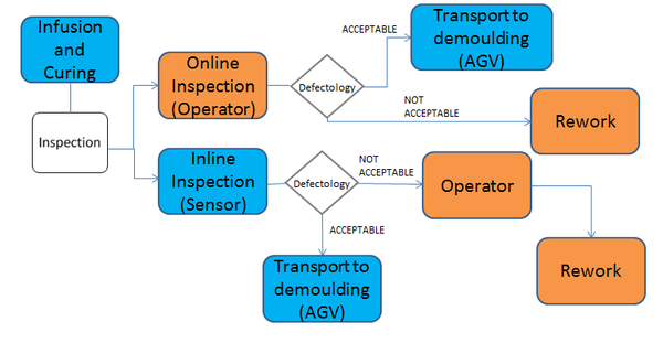
The inline inspection that will perform the control system is shown in the Figure 3.
Operators will inspect and act only when the error is detected by sensors. Several defects can be detected as angle deviation; late add, early cut and early add, late cut; missing tow; splices; gaps and overlaps; twist-DFP; fuzzball; defects in z-direction.
The control system has two sensors:
- Fscan: Sensor technology that uses a specific laser profile scanner to acquire 3D profiles during the AFP process.
- Lscan: Sensor technology using a reflection model of carbon fibre to measure fibre orientation. 3D information is not provided.
- In the infusion and curing processes the sensors monitor the temperature, flow rate and extent of the curing. If there is a variation of these parameters outside the acceptable limits, the ZAero system will act by correcting the parameters.
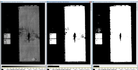
Porosity can be generated during the infusion and curing processes.
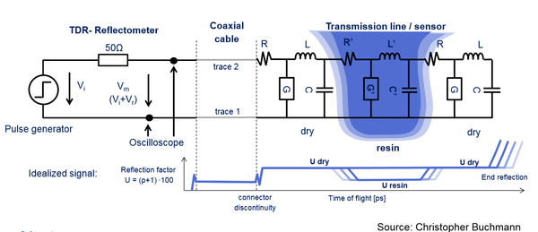
The sensor used to monitor infusion and curing processes is based on Electrical Time Domain Reflectometry (E-TDR) [2].
3 Materials and Technology
Two different technologies of automated lay-up which have similar needs for inspection will used:
- Dry Fiber Placement (DFP):
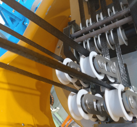
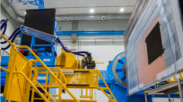
The machine will laminate with 8 tows of uniaxial material (12.7mm of width). Carbon fabric tows are very malleable themselves so as to make them manageable for manufacturing issues, they include binder onto their surfaces.
- Automated Dry Material Placement (ADMP):
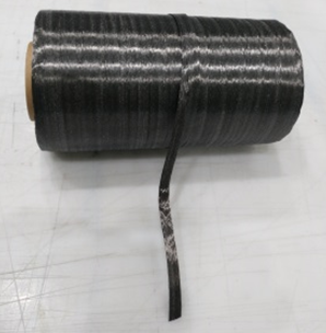
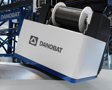
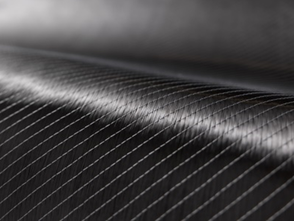
Multiaxial material with a width of 600mm will be placed. The tow curvature is lower in comparison with weave fabrics. The material has better mechanical properties.
The resin that will be used in the infusion and curing processes is a thermoset liquid epoxy resin.
Resin infusion processes techniques undergo both impregnation of the textile reinforcement and curing in the same moulding operation, thus providing cost reductions compared to prepreg technology.
The resin is enabling the parts to keep their final shape via chemical reaction (polymerization). Epoxy is a very versatile resin system, allowing a broad range of properties and processing capabilities.
4 Manufacturing Trials
Three parts will be manufactured. The degree of complexity will be increased in each demonstrator.
4.1 Demonstrator 1
This demonstrator part is mainly focused to test lay-up monitoring.
Defects will be induced during the manufacturing to assess the defect detection capabilities of the inline sensor systems.
A prototype system for inline quality control will be demonstrated.
4.2 Demonstrator 2
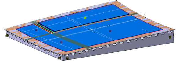
Second demo is oriented not only towards lay-up inspection, but also for curing monitoring. The dimensions of Demo 2 will be 1700x1700mm.
The demo part proposed is based on double curvature in order to identify potential lay-up defects as excessively wide gaps, overlaps, fuzz balls, twisted yarns, or other defects.
An intermediate version of the inline quality support will be demonstrated.
4.3 Demonstrator 3
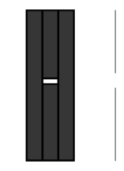
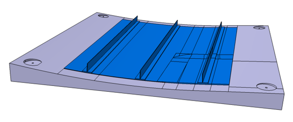
The third demo part is designed as demo part 2, but including three integrated stringers. These stringers have been defined as 3 “T” shape stringers:
The integration of the stringers in the demo part is necessary in order to test a real case of a stiffened panel for the infusion process.
A full version of the inline quality support will be demonstrated.
5 Project Plan
The duration of the project is 36 months (October 2016 to October 2019) [() ].
1st Demonstration will be planned to month 12 (October 2017).
2nd Demonstration will be planned to month 24 (October 2018).
3rd Demonstration will be planned to month 36 (October 2019).
6 Acknowledgements
This project has received funding from the European Union’s Horizon 2020 research and innovation programme under grant agreement No 721362.
7 References
[() ] ZAero-Grant Agreement(http://www.zaero-project.eu).
[2] BUCHMANN, C., FILSINGER, J. and LADSTÄTTER, E.: Investigation of Electrical Time Domain Reflectometry for Infusion and Cure Monitoring in Combination with Electrically Conductive Fibers and Tooling Materials. Composites Part B: Engineering, 94: 389-398 (2016).
Document information
Published on 29/04/18
Accepted on 29/04/18
Submitted on 29/04/18
Volume 02 - Comunicaciones Matcomp17 (2018), Issue Num. 2 - Aplicaciones y compuestos multifuncionales, 2018
DOI: 10.23967/r.matcomp.2018.04.020
Licence: Other
Share this document
Keywords
claim authorship
Are you one of the authors of this document?
