(Tag: Visual edit) |
|||
| Line 1: | Line 1: | ||
| − | <span id="_GoBack"></span> | + | Ftabla<span id="_GoBack"></span> |
==1 Scope of the study == | ==1 Scope of the study == | ||
| Line 173: | Line 173: | ||
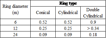
Three different diameters (6 m, 12 m and 24 m), were taken into account. Table 1 shows the mass efficiency of each configuration analysed for the same deployed stiffness requirements. | Three different diameters (6 m, 12 m and 24 m), were taken into account. Table 1 shows the mass efficiency of each configuration analysed for the same deployed stiffness requirements. | ||
| − | |||
<div class="center" style="width: auto; margin-left: auto; margin-right: auto;"> | <div class="center" style="width: auto; margin-left: auto; margin-right: auto;"> | ||
'''Table 1.''' Comparison of mass efficiency (kg/m<sup>2</sup>) of different ring configuration with the same deployed stiffness performance</div> | '''Table 1.''' Comparison of mass efficiency (kg/m<sup>2</sup>) of different ring configuration with the same deployed stiffness performance</div> | ||
| + | [[File:Nieto_et_al_2018a-image19.png|centre|339x339px]] | ||
| + | |||
| + | |||
Other considerations, regarding accuracy, thermal stability, deployment reliability, storage efficiency, kinematic simplicity, number of equal parts and cost were taken into account and weighted. The simple cylindrical ring resulted to be more adequate for the purpose of this project. | Other considerations, regarding accuracy, thermal stability, deployment reliability, storage efficiency, kinematic simplicity, number of equal parts and cost were taken into account and weighted. The simple cylindrical ring resulted to be more adequate for the purpose of this project. | ||
| Line 284: | Line 286: | ||
Once the main features of the designed linear and ring structures has been shown, tables 2 and 3 present a summary of the main deployable structures requirements and the values obtained. | Once the main features of the designed linear and ring structures has been shown, tables 2 and 3 present a summary of the main deployable structures requirements and the values obtained. | ||
| + | |||
| + | <div class="center" style="width: auto; margin-left: auto; margin-right: auto;"> | ||
| + | '''Table 2.''' Resume of linear deployable structure requirements compliance (until today)</div> | ||
{| style="width: 100%;border-collapse: collapse;" | {| style="width: 100%;border-collapse: collapse;" | ||
| Line 339: | Line 344: | ||
<div class="center" style="width: auto; margin-left: auto; margin-right: auto;"> | <div class="center" style="width: auto; margin-left: auto; margin-right: auto;"> | ||
| − | '''Table | + | '''Table 3'''. Resume of ring deployable structure with integrated network requirements compliance (until today)</div> |
{| style="width: 100%;border-collapse: collapse;" | {| style="width: 100%;border-collapse: collapse;" | ||
| Line 394: | Line 399: | ||
| − | + | ||
| − | + | ||
==10 Conclusion and further works== | ==10 Conclusion and further works== | ||
Revision as of 08:54, 6 October 2022
Ftabla
1 Scope of the study
The overall TRP activity scope is to design overall structural assemblies based on unit cells and develop representative part of deployable masts (linear structure) and rings (antenna or radiotelescope aperture).
The development covers the analytical predictions in combination with on-ground testing, and thereby also develops the verification methods. The expected development cost reduction of the modular architecture vs. non-modular is being quantified. Two different demonstrators models of deployable structures will be manufactured with due consideration to future mission needs: a linear structure to serve e.g. as baseline to carry a payload (e.g. reflector, instrument, antenna) on its tip and a ring type structure to serve as a backing structure for a reflector. The demonstrators will consist of a minimum of 6 modules.
2 Mission scenario definition
A search among several future missions has been carried out, taking into account the following considerations:
- For large reflectors (ring structures), and among others, two different kind of missions are candidates for this project:
- Earth observation missions, such as Biomass Mission, selected by ESA as an Earth Explorer Core Mission, with a synthetic aperture radar operating at P-band (435 MHz) with an elliptical 12 m reflector.
- Telecommunication missions, such as Inmarsat 6, which requires a 9 m reflector in L-band, with an elliptical 9 m reflector.
With the purpose of selecting the most challenging solution, a single configuration, valid for both kind of mission scenario would be a 12 m reflector working in L-Band. Thus, the overall requirements are those of the Biomass Mission, but the more demanding RMS error to the best-fit paraboloid of the Inmarsat, which is an L-band working antenna.
- Concerning the linear structure, both Biomass and Inmarsat reflectors are mounted on linear deployable structures which length is lesser than 20 m, which is the minimum length required by ESA for this project. For this reason, this length of 20 m has been selected for the current project. The deployable ring selected above will be allocated on top of this linear structure.
3 State of the art
A start of the art study has been performed, by means of analyzing current technologies that are being used for the deployment of linear and ring structures. Special attention has been paid on structures that are composed of unit cells that can potentially be used for both linear and ring structures. Structures that have been considered as non-modular or non-scalable have been discarded from the present study.
The study started with the ring deployable structures, as it has been considered that there are more unit cells used in this kind of structures that can be candidates for the deployment of both linear and ring structures.
3.1 Ring Deployable Structures
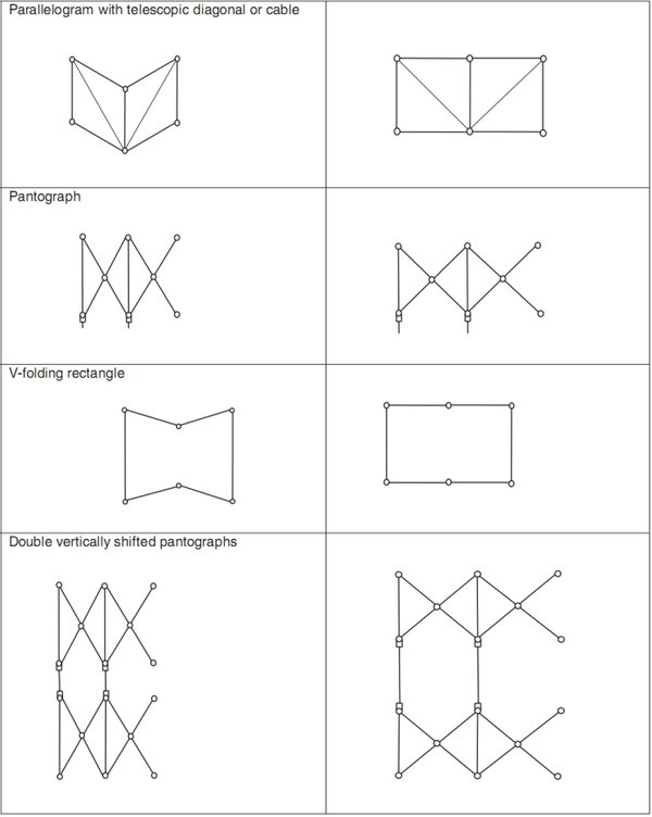
Several deployable ring structures have been analyzed and compared in terms of modularity, scalabilty, mass, stiffness, overconstraining, reliability, friction and motorisation. Reference [1] shows several of the planar bar linkages for space deployable antenna structures than can be considered as unit cells. They have already been used in space applications or are being developed by European space companies. Some of them are shown in figure below and they are:
- Parallelogram with telescopic diagonal,
- Double vertically stiffed pantograph,
- Pantograph,
- V-folding rectangle,
- Other combinations.
3.2 Linear Deployable Structures
Additionally, other linear deployable structures such as the ADAM mast, FAST mast and COILABLE mast were analysed and compared in order to evaluate common points, pros and cons, and adaptability of the unit cells they are composed of to a ring deployable structure.
4 Unit cell selection
Once all the options were compared, and based on the project requirements, the unit cell selected for the deployment of both ring and linear structures has been determined to be composed of two consecutive V-folding rectangles with a common non-deployable side. The synchronization of both V-folding rectangles will be done via cables and pulleys. This cables and pulleys system can connect adjacent unit cells so a chain of unit cells can be built. These chains do not necessarily have to be coplanar. Figure 2 shows this unit cell.
Each V-folding is self-deployed by a spring. By this way, the deployment of the unit cell is passive. The need of active motorization is suppressed, and only a cable is needed to control the unit cell deployment.
The combination of a series of synchronised couples of V-fold rectangles can lead to different deployable structures, such as:
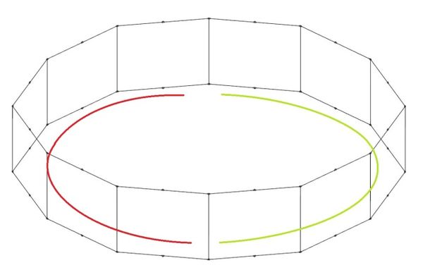
- A deployable ring structure composed of two chains of unit cells (one at each semi-ring),
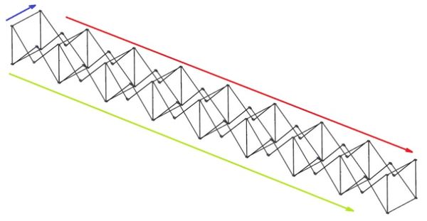
- A deployable linear structure composed of two parallel chains connected by rigid battens,
- Many other deployable structures composed of a series of chains of unit cells. For instance a modular deployable reflector composed of hexagonal cells composed by linear chains.
Figures 3 to 5 show the deployable structures commented above.
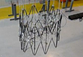
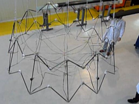
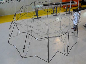
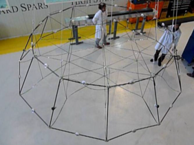
COMET and PROSIX have successfully developed and tested a 4 meter deployable ring with an inner cable network, demonstrating the viability of this unit cell, its synchronisation system, the possibility of combinations of these unit cells and the robustness and reliability of this kind of structures. Figure 6 shows the deployment test of a deployable conical ring structure, tested in December 2014.
5 Ring deployable structure alternatives
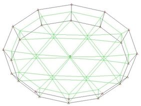
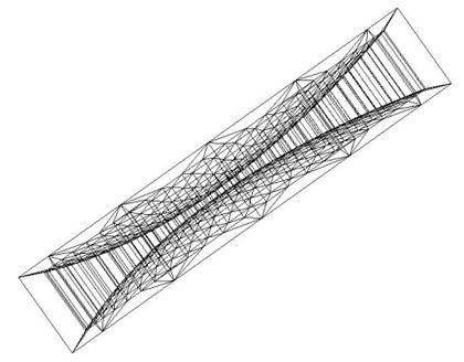
The unit cell selected for the project has demonstrated to fulfil the deployed stiffness requirement of a deployable ring if this ring is considered in several configurations: a conical ring, a simple cylindrical ring and a double cylindrical ring. For that reason, a stiffness, feasibility, reliability and cost study was carried out in order to determine the ring optimum configuration in the range of deployment of the present project. Figure 7 shows some of the Finite Element Models used for the determination of the deployed structures eigen-frequencies:
Three different diameters (6 m, 12 m and 24 m), were taken into account. Table 1 shows the mass efficiency of each configuration analysed for the same deployed stiffness requirements.
Other considerations, regarding accuracy, thermal stability, deployment reliability, storage efficiency, kinematic simplicity, number of equal parts and cost were taken into account and weighted. The simple cylindrical ring resulted to be more adequate for the purpose of this project.
6 Preliminary design of linear deployable structure
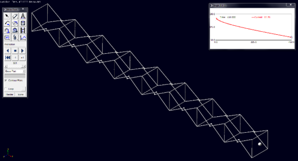
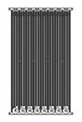
Once the unit cell and the linear architecture have been selected, unit cell requirements have been derived for the linear structures. The unit cell has been sized and designed according to these requirements and this unit cell has been assembled in order to build a 20 meter deployable linear structure. Figure 8 shows the modular deployable linear structure design in folded and deployed positions.
|
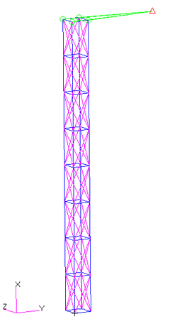
The stiffness of the deployed configuration has been calculated, providing an eigenfrequency of 1.3 Hz. In order to fully accomplish with the structure requirements, the structure has been reinforced with cable crossings (in magenta in figure 9) in order to increase its stiffness.
|
This configuration provides an excellent deployment ratio between stowed and deployed length of less than 5%, which is a very promising value not only for this particular mission specification, but for longer masts.
Friction, cables and other dynamic effects have been included in the functional analysis. Reliability of the deployment has also been assessed by means of dynamic multibody simulations, where the springs’ stiffness, friction coefficients and other factors have been altered obtaining successful deployments.
Actuation margins of the deployment have been calculated according to ECSS-E-ST-33-01C, resulting in values higher than 1.
Deployment accuracy (SRO) has also been assessed, providing values of 1.2 mm (6·10-5 x Length).
7 Preliminary design of deployable ring structure
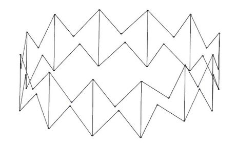
The unit cell selected in paragraph 4 has been combined as in previous fig. 4 in a simple elliptical ring. Fig. 11 shows the deployed and semi-deployed status of this structure.

|
Ratio between the folded diameter and the deployed diameter is lesser than 10%, providing excellent perspectives regarding its launcher accommodation.
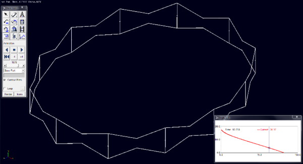
The same kinds of friction, springs and cables have been introduced in the functional analyses, obtaining actuation margins higher than 1. Reliability of the deployment has also been checked by means of altering these characteristics, providing successful deployments. Fig. 12 shows a frame of one of these analyses.
Deployment accuracy (SRO) of the single ring has also been assessed, providing values of 0.42 mm.
8 Deployable ring cable network
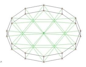
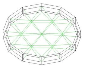
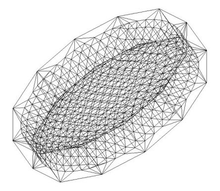
One key factor to be thoroughly taken into account when analysing a deployable reflector is the effect of the cable network on it. A cable network has been designed for the deployable ring structure that can be seen in fig. 13.
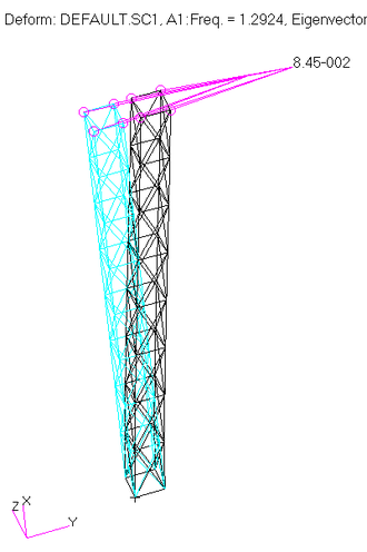
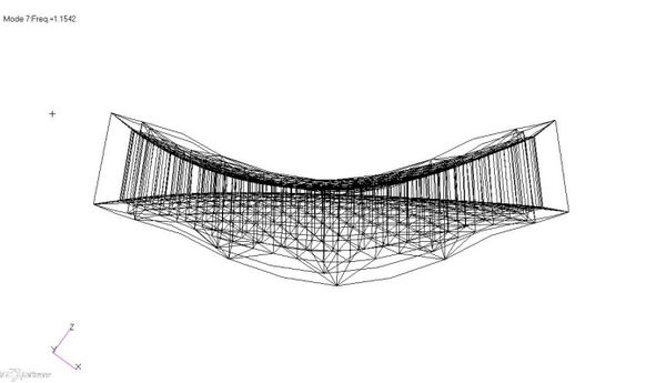
The stiffness of the designed reflector structure has been measured by means of a free-free modal analysis, resulting in a first eigenfrequency of 1.15 Hz, which mode can be seen in fig. 14.
The mass of the designed reflector is less than 0.35 kg/m2.
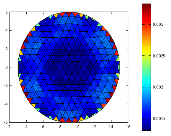
Regarding the reflector accuracy, the reflecting surface is form by flat facets. The nodes position has been optimised for having the minimum possible RMS error with respect to the theoretical paraboloid surface with this number of facets. The global RMS error of the designed faceted surface is 1.68 mm. Figure 15 shows the facets RMS. It is interesting to mark that very good RMS values are obtained at the center of the reflector.
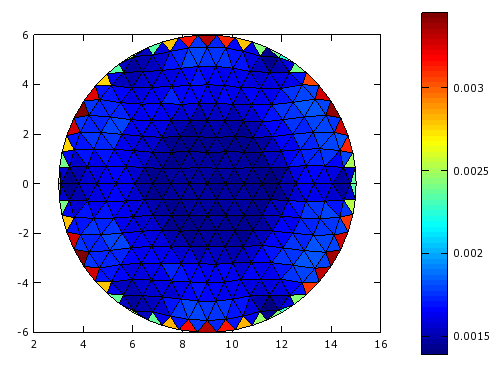
Concerning thermo-elastic stability, the RMS error of the deformed surface after best-fitting adjustment for the worst case (-170 °C) is 1.71 mm, as it can be seen in fig. 16.
9 Resume of requirements
Once the main features of the designed linear and ring structures has been shown, tables 2 and 3 present a summary of the main deployable structures requirements and the values obtained.
| Requirement | Value Required | Goal | Achieved in this project (until today) | |
| L1. Length | 20 to 50 m | 20 m | ||
| L2. Mass | < 5 kg · m-1 | 1 kg · m-1 | 3.89 kg · m-1 | |
| L3. Stowed Stiffness(1) | > 50 Hz | 55 Hz | ||
| L4. Deployed Stiffness(2) | > 1Hz | 1.3 Hz | ||
| L5. Accuracy (SRO) | < 2 mm | 0.2 mm | 1.2 mm | |
| L6. Stability (under thermal conditions) | < 2 mm | TBD | ||
| L7. Actuation Margin | > 1 | > 1 | ||
| L8. Envelope | Accomodation in Vega/Proton | Accomodation in ADS E3000 platform with Proton, Falcon 9 and Ariane 5 Sylda A upper position | ||
| (1) with HDRM concept | ||||
| (2) with 6m offseted punctual mass of 120kg. | ||||
| Requirement | Value Required | Goal | Achieved in this project (until today) |
| L1.Eliptical Geometry | D > 12m, d < 1.2m | D=20 m, d=0.9m | |
| L2. Mass | < 1 kg · m-2 | 0.1 kg·m-2 | 0.35 kg · m-2 |
| L3. Stowed Stiffness(1) | > 50 Hz | 52 Hz | |
| L4. Deployed Stiffness(2) | > 1Hz | 1.15 Hz | |
| L5. Accuracy (RMS) | < 2 mm (0-8m)
< 4 mm (8-12m) |
1.35 mm (0-8m)
2.11 mm (8-12m) | |
| L6. Stability (RMS under thermal conditions) | < 2 mm | 1.71 mm | |
| L7. Actuation Margin | > 1 | > 1 | |
| L8. Envelope | Accomodation in Vega/Proton | Accomodation in ADS E3000 platform with Proton, Falcon 9 and Ariane 5 Sylda A upper position |
10 Conclusion and further works
A unit cell has been selected for the common development of both linear and ring structures with very promising results. The simplicity and robustness of this unit cell is beneficially expanded to both deployable structures, resulting in lightweight, stable, accurate and robust products.
The number of common parts and mechanisms that are shared by both deployable structures foretells a cost decrease in their development.
The project is about to face Preliminary Design Review, where all the data provided in the present paper will be validated by ESA. Two breadboards will be manufactured and tested with the following aims:
- Deployment accuracy and reliability,
- Deployed stiffness,
- Stowed stiffness
References
[1] J. Santiago-Prowald, H. Baier. Advances in deployable structures and surfaces for large apertures in space. CEAS Space Journal. December 2013, Volume 5, Issue 3.
Document information
Published on 29/04/18
Accepted on 29/04/18
Submitted on 29/04/18
Volume 02 - Comunicaciones Matcomp17 (2018), Issue Num. 2 - Aplicaciones y compuestos multifuncionales, 2018
DOI: 10.23967/r.matcomp.2018.04.010
Licence: Other
Share this document
Keywords
claim authorship
Are you one of the authors of this document?
