(Created page with " <div class="center" style="width: auto; margin-left: auto; margin-right: auto;"> A.E. Jiménez Gahete<sup>a</sup></div> <div class="center" style="width: auto; margin-left:...") |
m (Materiales.Compuestos moved page Review 537262310925 to Gahete 2022a) |
||
| (2 intermediate revisions by the same user not shown) | |||
| Line 1: | Line 1: | ||
| − | |||
| − | |||
| − | |||
| − | |||
| − | |||
| − | |||
| − | |||
| − | |||
| − | |||
| − | |||
| − | |||
| − | |||
| − | |||
| − | |||
| − | |||
| − | |||
| − | |||
| − | |||
| − | |||
| − | |||
| − | |||
| − | |||
| − | |||
| − | |||
| − | |||
| − | |||
| − | |||
| − | |||
| − | |||
| − | |||
| − | |||
| − | |||
| − | |||
| − | |||
| − | |||
| − | |||
| − | |||
| − | |||
| − | |||
| − | |||
| − | |||
| − | |||
| − | |||
| − | |||
| − | |||
| − | |||
| − | |||
| − | |||
| − | |||
| − | |||
| − | |||
| − | |||
| − | |||
| − | |||
| − | |||
| − | |||
| − | |||
| − | |||
| − | |||
| − | |||
| − | |||
| − | |||
| − | |||
| − | |||
| − | |||
| − | |||
| − | |||
| − | |||
| − | |||
| − | |||
| − | |||
| − | |||
| − | |||
| − | |||
==1 Introduction== | ==1 Introduction== | ||
| Line 88: | Line 14: | ||
<div class="center" style="width: auto; margin-left: auto; margin-right: auto;"> | <div class="center" style="width: auto; margin-left: auto; margin-right: auto;"> | ||
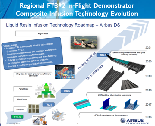
| − | <span style="text-align: center; font-size: 75%;">'''Figure 1. '''Airbus Defence and Space Infusion Technology Roadmap for TRL6 in 2022</span></div> | + | <span style="text-align: center; font-size: 75%;">'''Figure 1. '''Airbus Defence and Space Infusion Technology Roadmap for TRL6 in 2022.</span></div> |
In Clean Sky Airbus Defence and Space Airframe team has focused its attention in a overall weight reduction targets, together with manufacturing cost and cadency improvements, in comparison with actual structural components for primary structure, in military transport or regional aviation, although maintaining or improving, as far as possible, the functionalities considered as default in a reference structure. | In Clean Sky Airbus Defence and Space Airframe team has focused its attention in a overall weight reduction targets, together with manufacturing cost and cadency improvements, in comparison with actual structural components for primary structure, in military transport or regional aviation, although maintaining or improving, as far as possible, the functionalities considered as default in a reference structure. | ||
| Line 136: | Line 62: | ||
The ribs upper and lower flanges sit on top of the stringers feet and spar flanges. | The ribs upper and lower flanges sit on top of the stringers feet and spar flanges. | ||
| − | <div class="center" style="width: auto; margin-left: auto; margin-right: auto;"> | + | <div class="center" style="width: auto; margin-left: auto; margin-right: auto;">[[File:Captura de pantalla 2022-07-15 015907.png|centre|654x654px]]</div> |
| − | + | ||
<div class="center" style="width: auto; margin-left: auto; margin-right: auto;"> | <div class="center" style="width: auto; margin-left: auto; margin-right: auto;"> | ||
| Line 167: | Line 92: | ||
<div class="center" style="width: auto; margin-left: auto; margin-right: auto;"> | <div class="center" style="width: auto; margin-left: auto; margin-right: auto;"> | ||
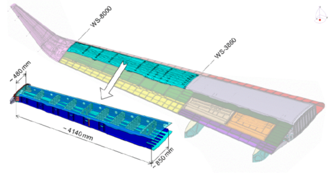
| − | <span style="text-align: center; font-size: 75%;">'''Figure 3. '''CFRP Outer External Wing Box Space Allocation Model</span></div> | + | <span style="text-align: center; font-size: 75%;">'''Figure 3. '''CFRP Outer External Wing Box Space Allocation Model.</span></div> |
''' [[Image:Draft_Compuestos_578095718-image8.png|600px]] ''' | ''' [[Image:Draft_Compuestos_578095718-image8.png|600px]] ''' | ||
<div class="center" style="width: auto; margin-left: auto; margin-right: auto;"> | <div class="center" style="width: auto; margin-left: auto; margin-right: auto;"> | ||
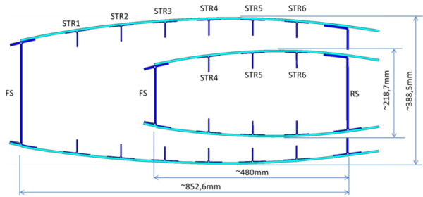
| − | <span style="text-align: center; font-size: 75%;">'''Figure 4. '''CFRP Wing Box cross sections at root and tip</span></div> | + | <span style="text-align: center; font-size: 75%;">'''Figure 4. '''CFRP Wing Box cross sections at root and tip.</span></div> |
[[Image:Draft_Compuestos_578095718-image9.png|600px]] | [[Image:Draft_Compuestos_578095718-image9.png|600px]] | ||
<div class="center" style="width: auto; margin-left: auto; margin-right: auto;"> | <div class="center" style="width: auto; margin-left: auto; margin-right: auto;"> | ||
| − | <span style="text-align: center; font-size: 75%;">'''Figure 5.''' Resin Infusion DEMO 1design. Front View</span></div> | + | <span style="text-align: center; font-size: 75%;">'''Figure 5.''' Resin Infusion DEMO 1design. Front View.</span></div> |
[[Image:Draft_Compuestos_578095718-image10.png|600px]] | [[Image:Draft_Compuestos_578095718-image10.png|600px]] | ||
<div class="center" style="width: auto; margin-left: auto; margin-right: auto;"> | <div class="center" style="width: auto; margin-left: auto; margin-right: auto;"> | ||
| − | <span style="text-align: center; font-size: 75%;">'''Figure 6.''' Resin Infusion DEMO 1</span></div> | + | <span style="text-align: center; font-size: 75%;">'''Figure 6.''' Resin Infusion DEMO 1.</span></div> |
DEMO 2 consists of a 3m long flat panel (skin) with 2 embedded spars and 5 stringers. Although it is flat, it simulates the actual outer external wing box overall dimensions. Each spar integrates 4 vertical stiffeners. | DEMO 2 consists of a 3m long flat panel (skin) with 2 embedded spars and 5 stringers. Although it is flat, it simulates the actual outer external wing box overall dimensions. Each spar integrates 4 vertical stiffeners. | ||
| Line 193: | Line 118: | ||
<div class="center" style="width: auto; margin-left: auto; margin-right: auto;"> | <div class="center" style="width: auto; margin-left: auto; margin-right: auto;"> | ||
| − | <span style="text-align: center; font-size: 75%;">'''Figure 7''' Resin Infusion DEMO 2 design</span></div> | + | <span style="text-align: center; font-size: 75%;">'''Figure 7''' Resin Infusion DEMO 2 design.</span></div> |
<div class="center" style="width: auto; margin-left: auto; margin-right: auto;"> | <div class="center" style="width: auto; margin-left: auto; margin-right: auto;"> | ||
| Line 199: | Line 124: | ||
<div class="center" style="width: auto; margin-left: auto; margin-right: auto;"> | <div class="center" style="width: auto; margin-left: auto; margin-right: auto;"> | ||
| − | <span style="text-align: center; font-size: 75%;">'''Figure 8.''' Resin Infusion DEMO 2</span></div> | + | <span style="text-align: center; font-size: 75%;">'''Figure 8.''' Resin Infusion DEMO 2.</span></div> |
==4 Materials Mechanical Characterization and Structural Tests== | ==4 Materials Mechanical Characterization and Structural Tests== | ||
| Line 287: | Line 212: | ||
<div class="center" style="width: auto; margin-left: auto; margin-right: auto;"> | <div class="center" style="width: auto; margin-left: auto; margin-right: auto;"> | ||
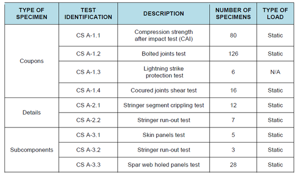
| − | <span style="text-align: center; font-size: 75%;">'''Figure 9.''' Development Test Matrix</span></div> | + | <span style="text-align: center; font-size: 75%;">'''Figure 9.''' Development Test Matrix.</span></div> |
<div class="center" style="width: auto; margin-left: auto; margin-right: auto;"> | <div class="center" style="width: auto; margin-left: auto; margin-right: auto;"> | ||
| Line 293: | Line 218: | ||
<div class="center" style="width: auto; margin-left: auto; margin-right: auto;"> | <div class="center" style="width: auto; margin-left: auto; margin-right: auto;"> | ||
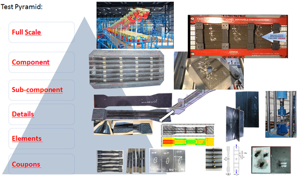
| − | <span style="text-align: center; font-size: 75%;">'''Figure 10.''' Test Pyramid</span></div> | + | <span style="text-align: center; font-size: 75%;">'''Figure 10.''' Test Pyramid.</span></div> |
Coupons were tested for residual strength after Impact, bolted joints, co cured shear joints and for lightning strike. The following figures are examples of two of the different type of coupons tests that have been conducted for development: (co-infused) shear tests and lightning strike coupons tests. | Coupons were tested for residual strength after Impact, bolted joints, co cured shear joints and for lightning strike. The following figures are examples of two of the different type of coupons tests that have been conducted for development: (co-infused) shear tests and lightning strike coupons tests. | ||
| Line 301: | Line 226: | ||
<div class="center" style="width: auto; margin-left: auto; margin-right: auto;"> | <div class="center" style="width: auto; margin-left: auto; margin-right: auto;"> | ||
| − | <span style="text-align: center; font-size: 75%;">'''Figure 11.''' Cocured shear joint coupons test</span></div> | + | <span style="text-align: center; font-size: 75%;">'''Figure 11.''' Cocured shear joint coupons test.</span></div> |
[[Image:Draft_Compuestos_578095718-image16.png|600px]] | [[Image:Draft_Compuestos_578095718-image16.png|600px]] | ||
<div class="center" style="width: auto; margin-left: auto; margin-right: auto;"> | <div class="center" style="width: auto; margin-left: auto; margin-right: auto;"> | ||
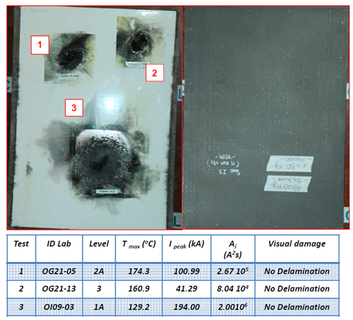
| − | <span style="text-align: center; font-size: 75%;">'''Figure 12''' '''.''' Lightning strike coupons test with bronce mesh</span></div> | + | <span style="text-align: center; font-size: 75%;">'''Figure 12''' '''.''' Lightning strike coupons test with bronce mesh.</span></div> |
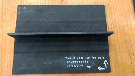
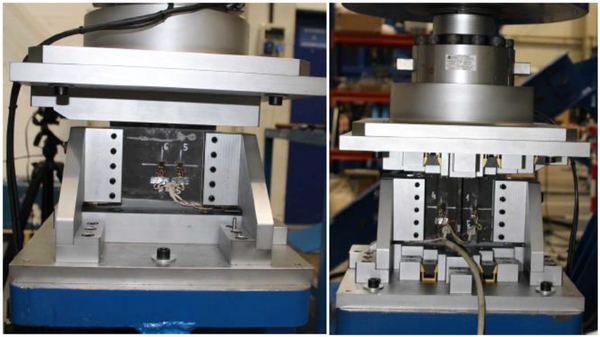
Design Details test matrix was also completed. In the next figures we can see pictures of stringer crippling specimen tests and stringer run-out tests. | Design Details test matrix was also completed. In the next figures we can see pictures of stringer crippling specimen tests and stringer run-out tests. | ||
| Line 314: | Line 239: | ||
<div class="center" style="width: auto; margin-left: auto; margin-right: auto;"> | <div class="center" style="width: auto; margin-left: auto; margin-right: auto;"> | ||
| − | <span style="text-align: center; font-size: 75%;">'''Figure 13.''' '''.'''Details Stringer Crippling Specimen</span></div> | + | <span style="text-align: center; font-size: 75%;">'''Figure 13.''' '''.'''Details Stringer Crippling Specimen.</span></div> |
<div class="center" style="width: auto; margin-left: auto; margin-right: auto;"> | <div class="center" style="width: auto; margin-left: auto; margin-right: auto;"> | ||
[[Image:Draft_Compuestos_578095718-image19.png|510px]] </div> | [[Image:Draft_Compuestos_578095718-image19.png|510px]] </div> | ||
| − | <div class="center" style="width: auto; margin-left: auto; margin-right: auto;"> | + | <div class="center" style="width: auto; margin-left: auto; margin-right: auto;">[[File:Captura de pantalla 2022-07-15 020009.png|centre|632x632px]]</div> |
| − | + | ||
<div class="center" style="width: auto; margin-left: auto; margin-right: auto;"> | <div class="center" style="width: auto; margin-left: auto; margin-right: auto;"> | ||
| − | <span style="text-align: center; font-size: 75%;">'''Figure 14.''' '''.'''Details''' '''Stringer Run Out Test</span></div> | + | <span style="text-align: center; font-size: 75%;">'''Figure 14.''' '''.'''Details''' '''Stringer Run Out Test.</span></div> |
Development test are being completed with subcomponent tests: 28 spar web holes panels in thick and thin panel configurations were tested with good results. Panels for compression and shear tests were also developed and successfully tested. The subcomponent test have finished with stringer run out panels also positively tested. | Development test are being completed with subcomponent tests: 28 spar web holes panels in thick and thin panel configurations were tested with good results. Panels for compression and shear tests were also developed and successfully tested. The subcomponent test have finished with stringer run out panels also positively tested. | ||
| Line 331: | Line 255: | ||
<div class="center" style="width: auto; margin-left: auto; margin-right: auto;"> | <div class="center" style="width: auto; margin-left: auto; margin-right: auto;"> | ||
| − | <span style="text-align: center; font-size: 75%;">'''Figure 15.''' '''.'''Subcomponents''' '''Spar web hole specimen</span></div> | + | <span style="text-align: center; font-size: 75%;">'''Figure 15.''' '''.'''Subcomponents''' '''Spar web hole specimen.</span></div> |
<div class="center" style="width: auto; margin-left: auto; margin-right: auto;"> | <div class="center" style="width: auto; margin-left: auto; margin-right: auto;"> | ||
| Line 337: | Line 261: | ||
<div class="center" style="width: auto; margin-left: auto; margin-right: auto;"> | <div class="center" style="width: auto; margin-left: auto; margin-right: auto;"> | ||
| − | <span style="text-align: center; font-size: 75%;">'''Figure 16.''' '''.'''Subcomponents''' '''Spar web hole tests</span></div> | + | <span style="text-align: center; font-size: 75%;">'''Figure 16.''' '''.'''Subcomponents''' '''Spar web hole tests.</span></div> |
<div class="center" style="width: auto; margin-left: auto; margin-right: auto;"> | <div class="center" style="width: auto; margin-left: auto; margin-right: auto;"> | ||
| Line 343: | Line 267: | ||
<div class="center" style="width: auto; margin-left: auto; margin-right: auto;"> | <div class="center" style="width: auto; margin-left: auto; margin-right: auto;"> | ||
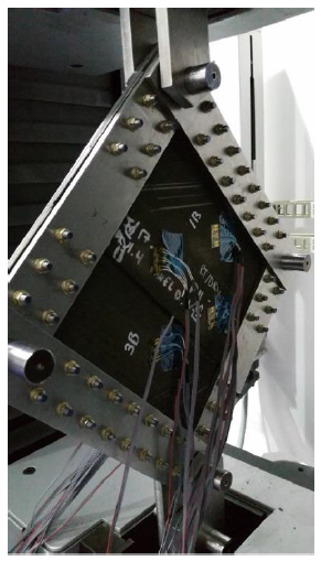
| − | <span style="text-align: center; font-size: 75%;">'''Figure 17.''' Subcomponents Skin Panel Shear Tests </span></div> | + | <span style="text-align: center; font-size: 75%;">'''Figure 17.''' Subcomponents Skin Panel Shear Tests.</span></div> |
<div class="center" style="width: auto; margin-left: auto; margin-right: auto;"> | <div class="center" style="width: auto; margin-left: auto; margin-right: auto;"> | ||
| Line 349: | Line 273: | ||
<div class="center" style="width: auto; margin-left: auto; margin-right: auto;"> | <div class="center" style="width: auto; margin-left: auto; margin-right: auto;"> | ||
| − | <span style="text-align: center; font-size: 75%;">'''Figure 18.''' Subcomponents'''.'''Skin Panel Compression Tests</span></div> | + | <span style="text-align: center; font-size: 75%;">'''Figure 18.''' Subcomponents'''.'''Skin Panel Compression Tests.</span></div> |
<div class="center" style="width: auto; margin-left: auto; margin-right: auto;"> | <div class="center" style="width: auto; margin-left: auto; margin-right: auto;"> | ||
| Line 355: | Line 279: | ||
<div class="center" style="width: auto; margin-left: auto; margin-right: auto;"> | <div class="center" style="width: auto; margin-left: auto; margin-right: auto;"> | ||
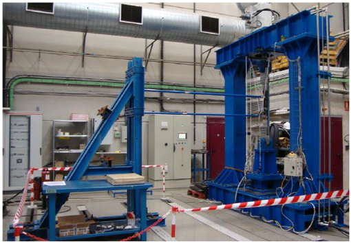
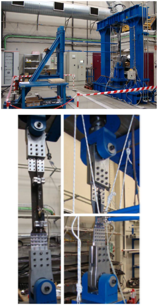
| − | <span style="text-align: center; font-size: 75%;">'''Figure 19.''' Subcomponents Stringer Run Out Panels Tests</span></div> | + | <span style="text-align: center; font-size: 75%;">'''Figure 19.''' Subcomponents Stringer Run Out Panels Tests.</span></div> |
==5 Conclusions== | ==5 Conclusions== | ||
Latest revision as of 01:06, 15 July 2022
1 Introduction
The Clean Sky 2 is a European Union Research and Technology Program. Airbus Defense and Space entered in the project as former EADSCASA and participates as formal Spanish company into European Frame Programs within different platforms and Integrated Technology Demonstrators (ITD).
Starting as ITD co-leader in Clean Sky 1 within Green Regional Aircraft (GRA), and also covering a wide range of research streams, now in Clean Sky 2 (CS2) our involvement has been enlarged co-leading AIRFRAME ITD and as responsibles of the Flight Test Bed 2 (FTB#2) in the REGIONAL Integrated Aircraft Demonstrator Platform (IADP).
Airbus Defence and Space objectives in CS2 program are to investigate and develop, until reaching Technological Readiness Level (TRL) 5 and 6, a set of technological lines of direct application to a future turboprop Regional aircraft. The program estimated duration is established in 7 years with the option of 3 additional years. CS2 start was established by August 2014 (REGIONAL IADP) and September 2014 (AIRFRAME ITD).
In the Airframe structure area Airbus Defence and Space Structures activities are mainly dedicated to develop the FTB#2 external wing. More specificly, and being the main subject of this paper, the outer external wing section, which is devoted to investigate carbon fibre reinforced plastic composite structures.
By means of On Ground and In Flight Demonstrator we are accomplishing the design, manufacture and test of highly integrated composite airframe primary structures. We are developing Out of Autoclave manufacturing processes, including Automatic Fibre Placement means for dry fiber materials and Liquid Resin Infusion manufacturing systems. The materials selected have been characterized. Step by step, we are going through the entire airframe structures test pyramid from coupons to the full scale structural tests of the outer wing.
In Clean Sky Airbus Defence and Space Airframe team has focused its attention in a overall weight reduction targets, together with manufacturing cost and cadency improvements, in comparison with actual structural components for primary structure, in military transport or regional aviation, although maintaining or improving, as far as possible, the functionalities considered as default in a reference structure.
Any future a/c design will require more eco-efficiency into the whole life cycle. Translation of this requirement into the a/c design and manufacturing should mean aspects being explored in conjunction with other improved functionality from several perspectives:
- Less energy into the component production
- Less scrap primary material
- Decreasing consumption of manufacturing liquids & ancillary
- Increasing recyclability
Infusion technology developments in Clean Sky 2 started with previous R&T projects such us Clean Sky 1 Green Regional Aircraft (GRA), ECODESIGN, APOLO and CERTERIN.
2 Materials Selection
Out-of-autoclave processes are key elements to achieve above mentioned program goals. Automatic Dry Fiber Placement materials and Liquid Resin Infusion processes have been selected. Material and processes properties characterization needed for wing box covers and spars have been conducted.
2.1 Dry Carbon Fiber and Epoxy Resin Materials
HEXCEL HiTape® UID210gsm / IMA / 2xV800E 4g/m2 (12.7 mm tow width).
Fiber: HexTow® IMA-GP 12K Intermediate Modulus Carbon Dry Tape
Carbon Fiber nominal weight: 210g/m2
Thermoplastic veil V800E on both sides. Veil weight 4g/m2 per side.
Tow width 12,7 mm
Resin: HexFlow® RTM6 180ºC Epoxy system.
3 Outer Wing Structural Design Concept
The infusion lower cover is composed of a variable thickness skin with integrated variable thickness stringers and spars.
The wing equips inverted J-section front and rear spars. There are two main reasons that lead to this design: T shape is preferred when the joint is co-cured, but when it is a mechanical joint (riveted), L shape is the preferred option. Then, for this case, it would lead to inverted J-section spars.
The stringers are T-section. The stringers webs are set perpendicular to the chord plane, and so parallel one to each other and parallel to rear spar. Webs perpendicular to the wing skin have been discarded. This is due to several reasons: one of them is the nature of the manufacturing process for the thermoplastic upper skin; it is also necessary to have all stringers webs in parallel planes for the assembly process conceived between ribs and the integrated part composed of lower skin+ stringers + spars component.
Taking into account the composite box section dimensions 4140mm length span wise and widths of 850mm at root and 480mm at tip, a maximum of six stringers could be fitted between spars at root rib and only 3 of these stringers could be fitted at end rib. Then, three of the stringers end in intermediate positions.
The box stringers feet are dimensioned for the riveted joints with ribs at the feet and potential riveted repair needs. In addition, the riveting between the stringers feet, directly onto the skin, was also taken into account.
The ribs upper and lower flanges sit on top of the stringers feet and spar flanges.
Apart from coupons and, prior to details and panels subcomponent tests to obtain the design allowables it was required to investigate and validate which design features can be obtained with the selected manufacturing processes.
For such purposes, together with the preliminary design of the wing box, manufacturing demonstrators were designed and manufactured:
- Infusions DEMO1 and DEMO2
Design feature expected to be incorporated to the external wing box were represented into these manufacturing parts demonstrator. The design principles of the outboard external wing box (or CFRP wing box) are conditioned by the manufacturing capabilities associated to the new technologies selected for the upper skin and the one shot lower skin with spars.
Based on preliminary design principles and material mechanical properties the demonstrators were sized and designed.
3.1 Infusion Manufacturing Demonstrators
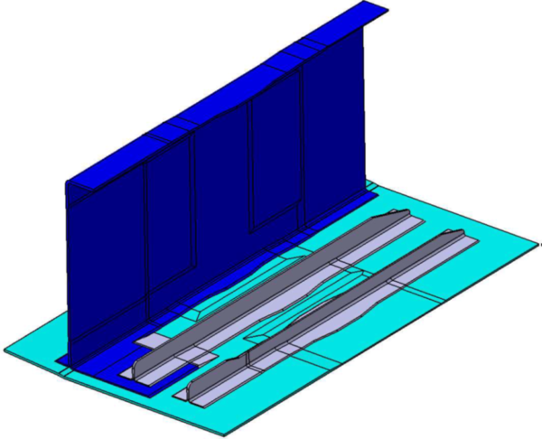
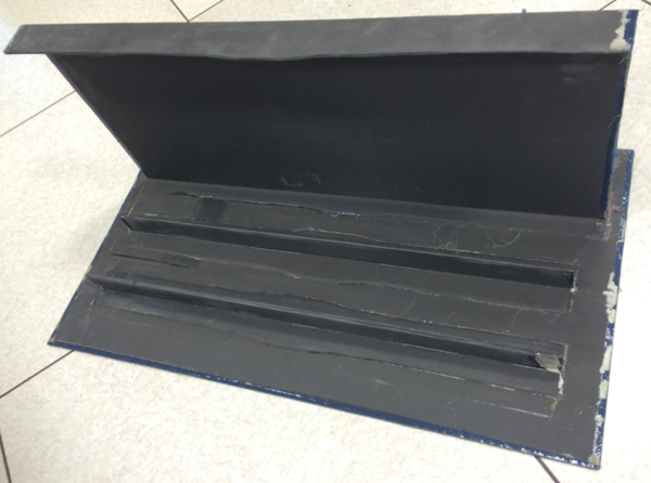
DEMO 1 consists of a flat skin of different thicknesses with a stage simulating the leading edge interface and with two integrated stringers and a J-section spar. The spar sits on top of the skin stage and it also integrates a vertical stiffener. One of the stringers sits on top of the spar flange part of its length. The demonstrator overall dimensions are 800x444x345mm (LxWxH). Front and rear views of the demonstrator are shown in next figures, respectively.
The skin, were the spar and stringers sit, has four different thickness areas, creating reinforcements and pools to which the elements on top must adapt. Hence, the spar is placed on top of a reinforcement and stringer 1 on top of a pool.
Stringer 1 sits entirely on top of the skin. It has a thickness change and its associated height change. Its width and height is determined as per that considered in the preliminary sizing.
Part of stringer 2 sits on the spar lower flange, which is extended to provide such support, and the rest on top of the skin. Stringer 2 is of constant thickness all along its length.
The spar is J-section, with the T-cap end sitting on the skin. The spar laminates are different between web and caps, and it incorporates several thickness changes.
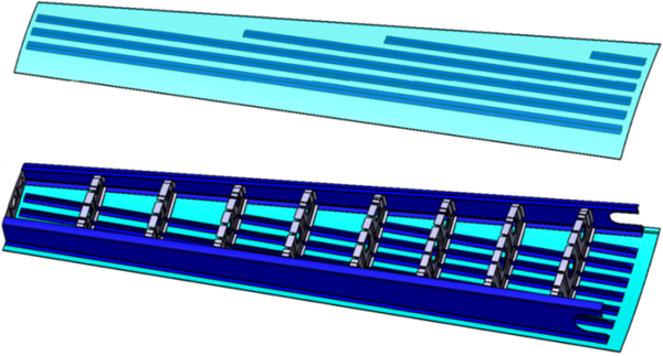
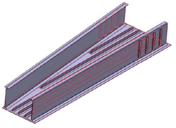
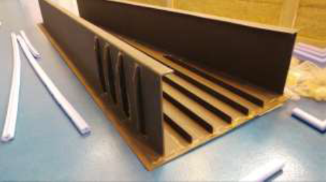
DEMO 2 consists of a 3m long flat panel (skin) with 2 embedded spars and 5 stringers. Although it is flat, it simulates the actual outer external wing box overall dimensions. Each spar integrates 4 vertical stiffeners.
Of the 5 stringers, 3 go from end to end of the panel, whereas the other two end at a certain distance, facing the front spar lower flange. All 5 include a typical run-out. The relative position between the different elements is set as per the actual wing box.
The demonstrator overall dimensions are 3000x860x344mm (LxWxH). A general view of the demonstrator is shown in the next figure. All elements are of constant section and thickness and their laminates are obtained from preliminary sizing of the final wing parts design.
4 Materials Mechanical Characterization and Structural Tests
Dedicated mechanical characterization test campaigns has been conducted. B-basis and H/W environmental conditions have been considered.
The process of the Outer External Wing structure substantiation for the permit to fly also includes:
- The definition and realization of developmental tests when allowable data are missing or analyses require experimental support.
- The realization of qualification static and functional tests on a complete representative outer external wing.
4.1 Material Mechanical Characterization
Material mechanical characterization tests are aimed to verify that both the material and the manufacturing processes result in mechanical performances adequate for the design of the external outer wing box of FTB#2 aircraft.
Materials that have been mechanically characterized:
Infusion materials: HEXCEL Hi Tape UD210 / RTM6
The following tests have been performed either in RT/Dry or Hot/Wet (coupons conditioned at 70ºC/85%RH and tested at 70ºC):
- Unidirectional properties:
- Unidirectional tension strength and modulus.
- Unidirectional compression strength and modulus.
- In-plane shear strength and modulus.
- Interlaminar shear strength.
- Interlaminar fracture toughness energy.
- Multiangular properties:
- Multiangular plain tension strength and modulus.
- Multiangular open and filled hole tension.
- Multiangular plain compression strength and modulus.
- Multiangular open and filled hole compression.
- Compression after Impact (CAI).
- Bearing.
Results and conclusions from material characterization test campaign:
- The Material reached the expectations.
- Lamina properties showed, in general, good performances in modulus, and less in strength compared with prepreg material M21E/IMA used as reference for comparison.
- Cuasi-isotropic laminates showed good results compared to reference.
4.2 Structural Tests
The Structural Tests are aimed to support the design, analysis and qualification of the outer external wing box of the FTB#2 demonstrator aircraft of the program Clean Sky 2.
The test plan includes the following types of on-ground tests:
- Development tests intended to:
- Derive design allowable values.
- Support the applicability of the analytical strength procedures and failure criteria used in the sizing and substantiation of the outer external wing box structure.
- Demonstrate fatigue and damage tolerance for composite fatigue sensitive features.
- Qualification tests aimed to demonstrate the structural integrity of the structure including:
- Static tests
- Residual strength tests
- Functional tests
- Lightning tests
For the Clean Sky 2 program, to obtain the FTB#2 outer wing qualification for flight, a component on-ground full scale static and functional test is planned. No fatigue and damage tolerance tests are planned on this component since only 100 flights (200 flight hours) are considered sufficient to fulfil the program objectives.
The text matrix is summarized in the next figure.
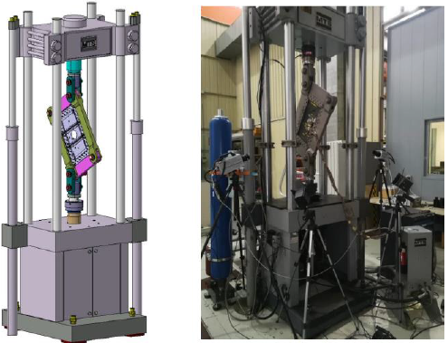
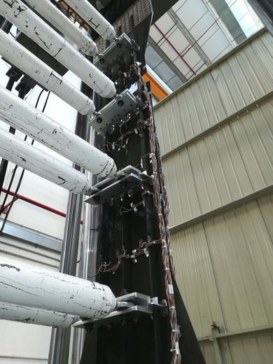
Coupons were tested for residual strength after Impact, bolted joints, co cured shear joints and for lightning strike. The following figures are examples of two of the different type of coupons tests that have been conducted for development: (co-infused) shear tests and lightning strike coupons tests.
Design Details test matrix was also completed. In the next figures we can see pictures of stringer crippling specimen tests and stringer run-out tests.
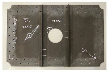
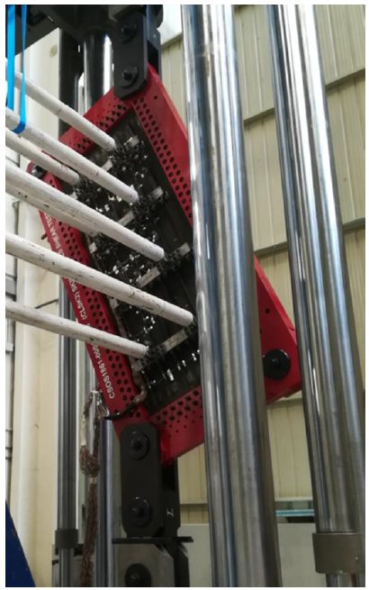
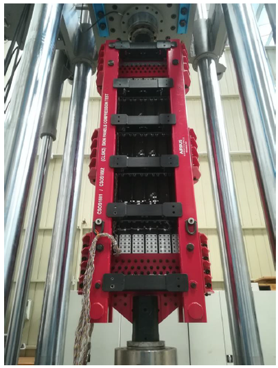
Development test are being completed with subcomponent tests: 28 spar web holes panels in thick and thin panel configurations were tested with good results. Panels for compression and shear tests were also developed and successfully tested. The subcomponent test have finished with stringer run out panels also positively tested.
5 Conclusions
Infusion technology manufacturing processes maturity has been progressing through the several steps of the technology evolution road map completed till now.
Difficulties encountered in the manufacturing have led to produce several trials of sample parts for the different specimens, and demanding adjustments of the process in a few iterations, before obtaining acceptable parts for the various structural tests performed.
After the measurement, inspection, and a careful analysis of the inspection reports of all the specimens produced, the specimens that were accepted for tests, achieved successful results in the different steps of the test pyramid completed, from coupons to subcomponents. Now, only the final outer wing full scale test planned is pending.
It was proved, through the material characterization campaign, that the stiffness and damage tolerant mechanical properties of the laminates obtained with the infusion materials and process are as those of the autoclave cured prepreg material IMA/M21E selected as reference for comparison.
At the beginning of the project the required half an inch material width format was not available, only the quarter of an inch width was offered. Thanks to the teamwork with material supplier the ½ inch width format was developed and adapted to the fiber placement machine available for laminating the details and subcomponent specimens, also demonstrating that laminates mechanical properties, obtained from ¼ inch format coupons, are applicable to the ½ inch width material format.
It has been a challenge to produce the manufacturing demos and subcomponent tests specimens without porosities defects whilst controlling the thickness tolerances. We have confirmed that thickness tolerances ranges are wider than those typical for prepreg autoclave processes or RTM systems. This characteristic has to be carefully taken into account in the definition and analysis of the interfacing surfaces of the infusion components, being specially challenging for highly integrated part conceived for the outer wing box.
Despite difficulties faced during the manufacturing, the technology evolution is very promising; we expect to complete the design of the outer wing box infusion components, together with the manufacturing tooling to produce it before the end of 2019.
We are on the way to demonstrate with the full scale test and the flight demonstrator that a large highly integrated structure can be produced with dry fiber placement and infusion processes, and that, when compared with reference airframe parts produced with prepreg materials and autoclave processes, costs reductions can be achieved. These technologies can be a real alternative for producing composite highly integrated parts for the aircraft primary structure.
Acknowledgments
What it has been achieved is due to the commitment and professionalisms of the Airbus Defence and Space Design, Stress, Manufacturing and Structural Test Engineering teams working in the project conceiving, designing, sizing and testing the demonstrators and the components described in this article. It is, as well, the result of the close collaboration with our partners, all the activities they have performed, and their efforts. Thanks to all of them, starting with those involved in the APOLO program HEXCEL (material supplier for the whole project also in Clean Sky), AERNNOVA, FIDAMC, TITANIA and CATEC. Our acknowledgment to all the companies involved in this technology development with Airbus Defence in the Clean Sky 2 project. We have to specially mention the FIDAMC team that produced the details specimens and subcomponent panels, while adjusting the infusion process. Not forgetting CTA, where the detail specimens (stringer crippling and run-out) tests have been conducted. And finally, MTORRES, which is designing and manufacturing the composite tooling for the infusion of the integrated final components for the wing box full scale and in flight demonstrators.
References
[1] M. Iglesias, R. Tejerina, F. Martín, A. Jiménez, J. García, ‘Structural Radar Research of Airbus Defense and Space as Clean Sky Partnership’ 8th European Conference For Aeronautics And Space Sciences, 2019
[2] M. Iglesias M. ‘TEDAE Sheet presentation’ Le Bourget Paris 2016
[3] M. Iglesias M. ´Proyecto europeo Clean Sky 2: Componentes estructurales de alta integración en nuevos materiales compuestos´ AEMAC May-2019 https://www.youtube.com/watch?v=lWWzo-XjMw0&t=742s
[4] Project Outcome (”OUT of autoclave COMpositE manufacturing, wing and tail unit components and multifunctional design” JTI-CS2-2014-CPW01-AIR-02-02) Grant Agreement Part B-I
Document information
Published on 15/07/22
Accepted on 15/07/22
Submitted on 15/07/22
Volume 04 - Comunicaciones Matcomp19 (2020), Issue Núm. 4 - Aplicaciones de los materiales compuestos. Nuevos procesos de fabricación y materiales compuestos avanzados., 2022
DOI: 10.23967/r.matcomp.2022.07.039
Licence: Other
Share this document
Keywords
claim authorship
Are you one of the authors of this document?
