(Created page with " <div class="center" style="width: auto; margin-left: auto; margin-right: auto;"> M. Laspalas<sup>a</sup>, I. Conde<sup>a</sup>, A. Chiminelli<sup>a</sup>, M. Lizaranzu<sup>a...") |
(Tag: Visual edit) |
||
| Line 1: | Line 1: | ||
| − | |||
| − | |||
| − | |||
| − | |||
| − | |||
| − | |||
| − | |||
| − | |||
| − | |||
| − | |||
| − | |||
| − | |||
| − | |||
| − | |||
| − | |||
| − | |||
| − | |||
| − | |||
| − | |||
| − | |||
| − | |||
| − | |||
| − | |||
| − | |||
| − | |||
| − | |||
| − | |||
| − | |||
| − | |||
| − | |||
| − | |||
| − | |||
| − | |||
| − | |||
| − | |||
| − | |||
| − | |||
| − | |||
| − | |||
| − | |||
| − | |||
| − | |||
| − | |||
| − | |||
| − | |||
| − | |||
| − | |||
| − | |||
| − | |||
| − | |||
| − | |||
| − | |||
| − | |||
| − | |||
| − | |||
| − | |||
| − | |||
| − | |||
| − | |||
| − | |||
| − | |||
| − | |||
| − | |||
| − | |||
| − | |||
| − | |||
| − | |||
| − | |||
==1 Introduction== | ==1 Introduction== | ||
Revision as of 18:50, 24 June 2022
1 Introduction
The part distortion problem such as spring-in (Figure 1) and warpage in the manufacture of thermoset composite parts has its origin in a series of physico-mechical mechanisms intrinsic to the composite material, such as chemical contraction, anisotropy of mechanical properties and coefficient of thermal expansion (CTE), as well as external, such as tool material properties, processing equipment and parameters, etc.
Given the high number of parameters and the complex interactions between them, the existence of part distortions is always an issue. In best case scenarios, this distortion hinders subsequent assembly operations, and in worst case scenarios the part is out of tolerances and must be reworked or rejected. Sometimes, the deformation of the part can be compensated in some extent in the assembly operation using different options such as introducing stiffeners, providing gaps that are then filled afterwards (shimming operations), etc. However, these solutions are not efficient from a technical or economic point of view.
Working on the optimisation of the processing conditions only provides some chances to mitigate deformation, so many times tool reworking is required to compensate undesired part deformation. Reaching tolerances typically requires to iterate with the tool design after the first manufacturing trials and distortion quantifications. Normally after two or three iterations the final tool is designed and the component is within tolerances. Nonetheless, from the point of view of costs and development time, this is not an optimum way to proceed.
In this context, the progress on the development of numerical tools and simulation methodologies will bring important benefits, first as a tool for deeper understanding on the effects and the sensitivity of the different parameters, and second to develop strategies to balance the parameters leading to a minimization of the final deformations in the part. The room for improvement using simulations is enormous, since it could lead to avoid tool iterations (first time right).
This contribution presents a numerical approach to predict distortions and compensate them by modifying the tool surface geometry.
2 FEM simulation workflow for distortion prediction
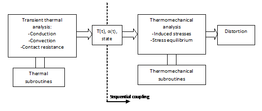
A simulation workflow to predict distortion typically requires two different analyses, as shown in a previous contribution of the authors [1]. The first one is a heat transfer analysis where two heating sources are considered: the power supplied to heat the tool and the exotermic heat flow created by the curing resin. Main heat transfer mechanisms considered are conduction, thermal contact resistances and convection over the external walls. The result is the temperature evolution over the full process.
The second analysis is a themo-mechanical analysis, where continuum solid mechanics is used to compute induced deformation. In this analysis the part-tool mechanical interactions, thermal expansions and chemical shrinkage are considered together with anisotropic state dependent material properties. Although these two analyses can be coupled and solved simultaneously the usual approach is to make them sequentally, first the heat transfer analysis, then the thermo-mechanical.
A curing kinetics model is introduced to determine the evolution of the degree of cure as a funciton of temperature hystory. This is usually represented in the form of the Kamal-Sourour model (1).
|
|
(1) |
Depending on the temperature and degree of cure three material states are considered. Under the gel point the resin is liquid and no chemical shrinkage/thermal expansion/mechanical stresses are present. Above the gel point the material enters in the rubbery state, initiating the building up of residual stresses. The change from rubbery state to glassy state is governed by the instantaneous glass transition temperature, which is a function of the degree of cure through the Di Benedetto equation (2). When the Tg of the material is equal to the actual temperature, the material changes from rubbery to glassy state. A jump in all the material properties must be introduced in this state.
|
|
(2) |
The thermal and mechanical properties of the composite in both, rubbery and glassy states, are computed from those in the constituents by micromechanical models. The properties of the resin in rubbery state are estimated from the glassy ones using the ratios between them given in Svangerg [2]. In this work a CHILE (curing hardenig instantaneous linear elastic model) is used [3].
3 Compensation simulation strategy
The proposed simulation strategy to compensate tool geometry is based on the one presented by Wucher et al [4],[5] which consists in modifying iteratively the mesh of a finite element model used for the prediction of process induced distortions until reaching the target geometry of the composite part.
The strategy is referred as an evolution of the "mirror method", which is based on the assumption that the distortions induced by the curing process are geometrically linear. Thus, the compensated geometry can be estimated from the inverse geometry of the deformed geometry. In this case, an iterative process of tool surface modification and distortion estimation is carried out, as described below, to generalise the approach (Figure 2).
In iteration 0, starting from a tool with the target geometry (tool geometry 0), the distortions of the cured part are predicted by the numerical model (cured geometry 0). The tool geometry in iteration 1 is the mirrowed one of the deformed geometry obtained in previous iteration. A new distortion simulation then will give a geometry closer to the target one, but as no linearities will still cause deviations, the difference between them is added to the geometry of iteration 1, thus obtaining the tool geometry for iteration 2. The process is repeated till cured part converges with target geometry.
The approach is implemented by updating the nodal coordinates of the part mesh following expression (3).
|
|
(3) |
Where:
- is the mesh coordinates of the target geometry.
- and are the mesh coordinates of the part in iteration i before and after curing respectively
Besides the nodal coordinates, also the element orientations are updated in each iteration by a projection method. The iterative process continues till the convergenge criteria is met, which is formulated in terms of a summatory of distances node to node between cured and target geometry (4).
|
|
(4) |
4 Implementation
The distortion simulation workflow (Figure 3) has been implemented by means of a collection of user subroutines in Abaqus/Standard:
- UEXTERNALDB: Manage reading and storage data
- UAMP: Control heating power
- HETVAL: Calculate the progression curing reaction and heat generated
- USDFLD: Determines the material state
- UEXPAN: Updates the expansions-contraction deformations due to thermal and curing effects.
The iterative process has been implemented in an external python manager represented in Figure 4.
First, the data corresponding to nodes of the part and tool in the target geometry are processed, and pairs of matching nodes are identified. Then, in each iteration, next steps are followed:
- The first step of the iterative process is to execute an Abaqus post-process script that writes the displacements obtained in the part after the curing and tool release process in the previous iteration. These displacements are processed and added to the coordinates of the nodes of the part before the calculation of the iteration, obtaining the coordinates of the nodes in this cured deformed state, calculating also the residual distance with respect to the target geometry (Equation 4). If this residual distance changes less than a given tolerance with regard to the previus iteration the iterative process is ended.
- In case of not meeting the convergence criterion, the second step is to update the coordinates of the nodes of the part and the paired tool surface nodes (Equation 3).
- The third step is to update the laminate orientations by a projection method.
- Finally, once the nodes and orientations have been updated, the new distortion calculation of the model with the updated mesh is executed and, if correctly finished, the results prepared for next iteration.
5 Application example
5.1 Component manufacturing
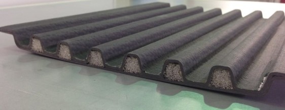
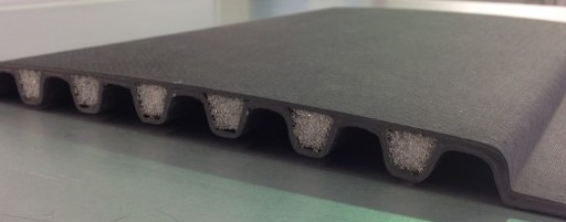
The application example is a 290 mm x 230 mm corrugated panel consisting of two composite skins and foam cores between them. The composite material is carbon fiber fabric G0926 in RTM6 resin from HEXCEL. The stacking of the lower skin is -45/90/90/-45 and 45/0/0/45 in the upper. The cores are made of ROHACELL foam.
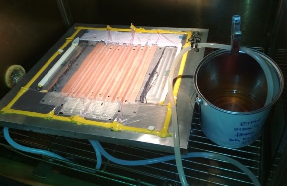
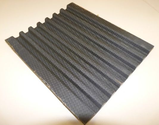
The infusion is performed under vacuum over a flat tool surface in a thermally controlled heating chamber. The resulting part is shown in Figure 6.
The part distortion after curing and releasing from the tool is significant, ranging the maximum out of plane displacement from 3.9 to 4.2 mm (Figure 7).
5.2 Model
The simulation methodology described in previous sections is applied to an aeronautical demonstrator, although in this simple case some simplifications are introduced. First, no heat transfer analysis is performed and directly the temperature history in the whole part is assumed as the cure cycle set to the climatic chamber. Second, no tool deformations are considered.
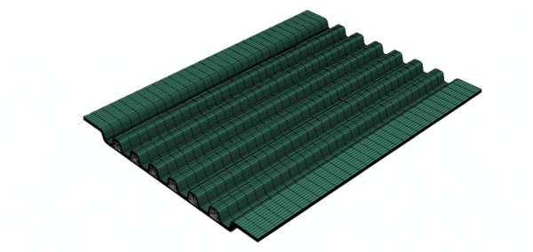
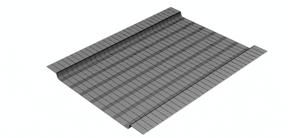
The FEM model of the corrugated component is shown in Figure 8 and the associated tool surface geometry in Figure 9.
The panel has been modeled with solid elements C3D8R from the Abaqus library. The lower tool (there is no upper tool since it is a vacuum resin infusion) has been modeled with R3D4 rigid elements with nodes coinciding with those of the part, which makes more eassy adapting its geometry in the iterative process. The interaction between part and tool surface has been represented by a contact algorithm with non-separation and frictionless options.
5.3 Boundary conditions
The calculation is made in six steps corresponding to the following phases of the process, starting from a preheating temperature of 85ºC:
- 1. Heating up to 150ºC (1ºC / min).
- 2. Curing at 150ºC (240 min).
- 3. Heating up to 180ºC (1ºC / min).
- 4. Curing at 180ºC (120 min).
- 5. Cooling to room temperature (157 min).
- 6. Release of the piece.
All the degrees of freedom of the rigid tool and the longitudinal displacement of one of the nodes of the composite part have been restricted during steps 1 to 5. In the final step the contact of tool and part is deactivated and apropiate restrictions in terms of velocity of three selected nodes of the parts prevent the rigid solid movements.
5.4 Results
Figure 10 shows the results in terms of displacements perpendicular to the plane of the component. Figure 10-a, the deformed configuration obtained in iteration 0 is showed, which results in a total out of plane displacement of 3.51 mm, acceptably close to the experimentally observed in the manufacturing trials.
The resulting updated mesh for iteration 1 can be seen in the Figure 10-b, that has the inverse curvature to the final deformation in iteration 0. Finally, the deformed geometry obtained at the end of iteration 1 is shown in Figure 10-c. As it can be seen, in the first iteration, the distortion presented by the panel has been mostly compensated, although numerically speaking, it is not until iteration 6 when the residual distance criteria is met.
Table 1 shows the evolution of this residual distance over the different iterations.
| Iteration | Dres |
| It0 | 184996.7 |
| It1 | 11051.8 |
| It2 | 1188.5 |
| It3 | 73.7 |
| It4 | 2.5 |
| It5 | 1.7 |
| It6 | 1.2 |
6 Conclusions
A simulation strategy has been developed based on an iterative mesh modification method that allows compensating the distortions in the composite part by varying the geometry of the tool surface. The implementation has been done in a Python manager script in conjunction with a distortion simulation workflow based on Abaqus/Standard.
The method based on the mesh modification is less expensive and faster than other complex CAD-based methods, only requiring a final post-processing to obtain CAD of the final compensated tool.
The tool has been applied to the simulation of the distortion in a corrugated panel of composite material with foam cores, obtaining good correlation in terms of part distortion prediction for the initial uncompensated tool. In this application case, most of the distortion has been eliminated with the modification of the mesh in the first iteration, reaching the minimum residual distance in iteration 6.
Acknowledgements
The tool developments have beel performed by ITAINNOVA in internal research projects partially funded by the European Social Fund (ESF).
The application case is performed within the Clean Sky program, in the framework of Hybrid Laminar Flow Control, where Aernnova is leading WP 141.
References
[1]A. Chiminelli, D. Fernando, M. Lizaranzu, M.A. Jiménez, M. Laspalas, J.R. Sainz de Aja, Materiales Compuestos, 15, pág.435-440 (2015).
ISBN: 978-84-697-0406-6
[2]J.M. Svanberg, Predictions of manufacturing induced shape distortions : high performance thermoset composites, Ph.D., Luleå tekniska universitet, 2002.
http://www.diva-portal.org/smash/record.jsf?pid=diva2:998979.
[3]A. Johnston, R. Vaziri, A. Poursartip, J. Compos. Mater, 35, page 1435–1469 (2001)
https://doi.org/10.1106%2FYXEA-5MH9-76J5-BACK
[4]B. Wucher, Ph. Martiny, F. Lani, T. Pardoen , C. Bailly, D. Dumas, Composites: Part A, 102, pág.96-107 (2017).
https://doi.org/10.1016/j.compositesa.2017.07.029
[5]B. Wucher, F. Lani, T. Pardoen , C. Bailly, Ph. Martiny,, Composites: Part A, 56, pág.27-35 (2014).
Document information
Published on 24/06/22
Accepted on 24/06/22
Submitted on 24/06/22
Volume 04 - Comunicaciones Matcomp19 (2020), Issue Núm. 2 - Procesos de Fabricación y Técnicas de Unión, 2022
DOI: 10.23967/r.matcomp.2022.06.041
Licence: Other
Share this document
Keywords
claim authorship
Are you one of the authors of this document?


