| Line 37: | Line 37: | ||
==2 TRMG motion mechanism== | ==2 TRMG motion mechanism== | ||
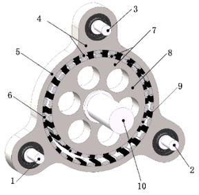
| − | Figure 1 shows the mechanical structure of TRMG. In | + | Figure 1 shows the mechanical structure of TRMG. In Figure 1, shaft 1, shaft 2, and shaft 3 are eccentric high-speed shafts, which are connected with ring-plate permanent magnet ring 4 through rolling bearings; The ring-plate permanent magnet ring 4 is composed of a ring plate (outer yoke) 5 and outer ring permanent magnet 6, and are located outside the low-speed permanent magnet ring 7; The low-speed permanent magnet ring 7 is composed of an inner yoke 8 and inner ring permanent magnet 9. In general, the difference between ring-plate permanent magnet ring and low-speed permanent magnet ring is 1 pair of magnetic pole pairs. |
<div id="TRMGmechanicalstructurediagram1" class="center" style="width: auto; margin-left: auto; margin-right: auto;"> | <div id="TRMGmechanicalstructurediagram1" class="center" style="width: auto; margin-left: auto; margin-right: auto;"> | ||
| Line 44: | Line 44: | ||
1-3. Eccentric high-speed shaft 4. Ring-plate permanent magnet ring 5. Ring plate 6. Outer ring permanent magnet 7. Low-speed permanent magnet ring 8. Inner yoke 9. Inner ring permanent magnet 10. Low-speed shaft | 1-3. Eccentric high-speed shaft 4. Ring-plate permanent magnet ring 5. Ring plate 6. Outer ring permanent magnet 7. Low-speed permanent magnet ring 8. Inner yoke 9. Inner ring permanent magnet 10. Low-speed shaft | ||
| − | '''Figure 1'''. TRMG mechanical structure diagram. | + | <span style="text-align: center; font-size: 75%;">'''Figure 1'''. TRMG mechanical structure diagram.</span> |
In Figure 1, the eccentricity of eccentric high-speed shafts is equal to the eccentricity from ring-plate permanent magnet ring to low-speed permanent magnet ring. Set the radius of low-speed permanent magnet ring and ring-plate permanent magnet ring respectively is <math display="inline">r_1</math> and <math display="inline">r_2</math> respectively, and the eccentricity of the high-speed shaft is <math display="inline">r</math> , then: <math display="inline">r=r_2-r_1</math> . | In Figure 1, the eccentricity of eccentric high-speed shafts is equal to the eccentricity from ring-plate permanent magnet ring to low-speed permanent magnet ring. Set the radius of low-speed permanent magnet ring and ring-plate permanent magnet ring respectively is <math display="inline">r_1</math> and <math display="inline">r_2</math> respectively, and the eccentricity of the high-speed shaft is <math display="inline">r</math> , then: <math display="inline">r=r_2-r_1</math> . | ||
| − | When anyone high-speed shaft shown in | + | When anyone high-speed shaft shown in Figure 1 drives the ring-plate permanent magnet ring to move, the outer ring permanent magnet rotates around the inner ring permanent magnet. Due to the change of the relative position of the two permanent magnets, the inner ring permanent magnet embedded in the low-speed permanent magnet ring rotates around its axis under the change of magnetic field force. Set the center of low-speed permanent magnet ring as <math display="inline">\mbox{O}_1</math> , the center of ring-plate permanent magnet ring as <math display="inline">\mbox{O}_2</math> , and the revolution angle speed of ring-plate permanent magnet ring as <math display="inline">\omega </math> , then the angular acceleration of <math display="inline">\mbox{O}_2</math> around <math display="inline">\mbox{O}_1</math> is <math display="inline">{\alpha }_{\mbox{O}2}\mbox{=}{\omega }^2r</math>, whose direction is from <math display="inline">\mbox{O}_2</math> to <math display="inline">\mbox{O}_1</math> . |
==3 TRMG kinetic model and equilibrium equation== | ==3 TRMG kinetic model and equilibrium equation== | ||
| Line 163: | Line 163: | ||
| − | If <math>F_\mbox{a}</math> , | + | If <math>F_\mbox{a}</math> , <math>F_\mbox{b}</math> , and <math>F_\mbox{c}</math> are set as the radial additional force acting on the ring-plate permanent magnet ring by the rolling bearing of each shaft respectively, then: |
{| class="formulaSCP" style="width: 100%; text-align: center;" | {| class="formulaSCP" style="width: 100%; text-align: center;" | ||
| Line 171: | Line 171: | ||
|- | |- | ||
| <math>\begin{array}{c} | | <math>\begin{array}{c} | ||
| − | F_{\mbox{Ar}}\mbox{=}{F^{{'}}}_{\mbox{Ar}}+F_\mbox{a}\\ | + | F_{\mbox{Ar}}\mbox{=}{F^{{ '}}}_{\mbox{Ar}}+F_\mbox{a} \\ |
| − | F_{\mbox{Br}}\mbox{=}{F^{{'}}}_{\mbox{Br}}+F_\mbox{b}\\ | + | F_{\mbox{Br}}\mbox{=}{F^{{ '}}}_{\mbox{Br}}+F_\mbox{b} \\ |
| − | F_{\mbox{Cr}}\mbox{=}{F^{{'}}}_{\mbox{Cr}}+F_\mbox{c} | + | F_{\mbox{Cr}}\mbox{=}{F^{{ '}}}_{\mbox{Cr}}+F_\mbox{c} |
\end{array}</math> | \end{array}</math> | ||
|} | |} | ||
| Line 187: | Line 187: | ||
{| style="text-align: center; margin:auto;" | {| style="text-align: center; margin:auto;" | ||
|- | |- | ||
| − | | <math>{F^{{'}}}_{\mbox{Ar}}={F^{{'}}}_{\mbox{Br}}={F^{{'}}}_{\mbox{Cr}}=</math><math>\frac{r_1L}{6{\mu }_0}{\int }_0^{2\pi }\left[B_\mbox{r}^2\left(\beta ,t\right)-\right. </math><math>\left. B_\mbox{t}^2\left(\beta ,t\right)\right]d\beta -</math><math>\frac{1}{3}I_\mbox{g}</math> | + | | <math>{F^{ { '}}}_{\mbox{Ar}}={F^{{ '}}}_{\mbox{Br}}={F^{{ '}}}_{\mbox{Cr}}=</math><math>\frac{r_1L}{6{\mu }_0}{\int }_0^{2\pi }\left[B_\mbox{r}^2\left(\beta ,t\right)-\right. </math><math>\left. B_\mbox{t}^2\left(\beta ,t\right)\right]d\beta -</math><math>\frac{1}{3}I_\mbox{g}</math> |
|} | |} | ||
| style="width: 5px;text-align: right;white-space: nowrap;" | (7) | | style="width: 5px;text-align: right;white-space: nowrap;" | (7) | ||
| Line 193: | Line 193: | ||
| − | In Equation (7), the inertia force <math display="inline">I_\mbox{g}\mbox{=}m{\alpha }_{\mbox{O}2}\mbox{=}m{\omega }^ | + | In Equation (7), the inertia force <math display="inline">I_\mbox{g}\mbox{=}m{\alpha }_{\mbox{O}2}\mbox{=}m{\omega }^2r</math> , where <math display="inline">m</math> is the weight of ring-plate permanent magnet ring. |
According to Equation (7), the difference between <math>F_{\mbox{Ar}}</math> , <math>F_{\mbox{Br}}</math> <sub>, </sub>and <math>F_{\mbox{Cr}}</math> are proportional to the additional force applied. | According to Equation (7), the difference between <math>F_{\mbox{Ar}}</math> , <math>F_{\mbox{Br}}</math> <sub>, </sub>and <math>F_{\mbox{Cr}}</math> are proportional to the additional force applied. | ||
| Line 270: | Line 270: | ||
(1) The radial force of each shaft in TRMG is composed of tangential and radial electromagnetic force of low-speed permanent magnet ring and the tangential force of input shaft. | (1) The radial force of each shaft in TRMG is composed of tangential and radial electromagnetic force of low-speed permanent magnet ring and the tangential force of input shaft. | ||
| − | (2) When | + | (2) When <math>\omega t</math>is equal to 0° or 180°, that is, when the crank AA' and the crank BB' are collinear with the connecting rod AB, <math>F_{\mbox{Cr}}</math> is larger than <math>F_{\mbox{Ar}}</math> and <math>F_{\mbox{Br}}</math> , indicating that the crank CC' drives the crank AA' and the crank BB' to move through ring-plate and making them pass through the collinear position smoothly. |
(3) Since the expressions of <math>F_{\mbox{Ar}}</math> , <math>F_{\mbox{Br}}</math> and <math>F_{\mbox{Cr}}</math> contain trigonometric functions of input tangential force and tangential electromagnetic force, the impact load of input shaft and support shafts can be reduced by reducing their amplitudes, to slow down the extrusion and elastic deformation caused by impact load and increase the service life of rolling bearings. | (3) Since the expressions of <math>F_{\mbox{Ar}}</math> , <math>F_{\mbox{Br}}</math> and <math>F_{\mbox{Cr}}</math> contain trigonometric functions of input tangential force and tangential electromagnetic force, the impact load of input shaft and support shafts can be reduced by reducing their amplitudes, to slow down the extrusion and elastic deformation caused by impact load and increase the service life of rolling bearings. | ||
| Line 280: | Line 280: | ||
===4.1 Analysis of TRMG electromagnetic characteristics=== | ===4.1 Analysis of TRMG electromagnetic characteristics=== | ||
| − | Set rated power is <math>P=1\mbox{kW}</math> rated output speed of low-speed permanent magnet ring is <math>n_\mbox{o}=70\mbox{r}/min</math> , transmission ratio is <math>i=22</math> , torque density is <math>T_\mbox{d}=148\mbox{kN}\cdot {\mbox{m/m}}^\mbox{3}</math> , flux leakage coefficient is 0.2.The static and dynamic electromagnetic fields that calculate the function of Ansys Maxwell are used to analyze the finite element structure of TRMG and TRMG parameters are optimized according to improved torque characteristics.Finally, TRMG electromagnetic model parameters as shown in Table 1 can be obtained. | + | Set rated power is <math>P=1\mbox{kW}</math> rated output speed of low-speed permanent magnet ring is <math>n_\mbox{o}=70\mbox{r}/mbox{min}</math> , transmission ratio is <math>i=22</math> , torque density is <math>T_\mbox{d}=148\mbox{kN}\cdot {\mbox{m/m}}^\mbox{3}</math> , flux leakage coefficient is 0.2. The static and dynamic electromagnetic fields that calculate the function of Ansys Maxwell are used to analyze the finite element structure of TRMG and TRMG parameters are optimized according to improved torque characteristics. Finally, TRMG electromagnetic model parameters as shown in Table 1 can be obtained. |
| − | '''Table 1.''' TRMG electromagnetic model parameters. | + | <span style="text-align: center; font-size: 75%;">'''Table 1.''' TRMG electromagnetic model parameters.</span> |
{| style="width: 100%;margin: 1em auto 0.1em auto;border-collapse: collapse;" | {| style="width: 100%;margin: 1em auto 0.1em auto;border-collapse: collapse;" | ||
|- | |- | ||
| − | | style="border: 1pt solid black;text-align: center;"|<span | + | | style="border: 1pt solid black;text-align: center;"|<span style="text-align: center; font-size: 75%;">'''Symbol'''</span> |
| style="border: 1pt solid black;text-align: center;"|<span style="text-align: center; font-size: 75%;">'''Description'''</span> | | style="border: 1pt solid black;text-align: center;"|<span style="text-align: center; font-size: 75%;">'''Description'''</span> | ||
| style="border: 1pt solid black;text-align: center;"|<span style="text-align: center; font-size: 75%;">'''Value (Unit)'''</span> | | style="border: 1pt solid black;text-align: center;"|<span style="text-align: center; font-size: 75%;">'''Value (Unit)'''</span> | ||
| Line 319: | Line 319: | ||
|- | |- | ||
| style="border: 1pt solid black;text-align: center;"|<span style="text-align: center; font-size: 75%;">'' <math display="inline">R_6</math> ''</span> | | style="border: 1pt solid black;text-align: center;"|<span style="text-align: center; font-size: 75%;">'' <math display="inline">R_6</math> ''</span> | ||
| − | | style="border: 1pt solid black;text-align: center;" | + | | style="border: 1pt solid black;text-align: center;"<span style="text-align: center; font-size: 75%;">Outer radius of inner yoke iron</span> |
| style="border: 1pt solid black;text-align: center;"|<span style="text-align: center; font-size: 75%;">88(mm)</span> | | style="border: 1pt solid black;text-align: center;"|<span style="text-align: center; font-size: 75%;">88(mm)</span> | ||
|- | |- | ||
| Line 351: | Line 351: | ||
<div class="center" style="width: auto; margin-left: auto; margin-right: auto;"> | <div class="center" style="width: auto; margin-left: auto; margin-right: auto;"> | ||
| − | + | [[Image:Draft_Liu_692227147-image77.png|300px]]</div> | |
<span id='Relationship4'></span><span style="text-align: center; font-size: 75%;">'''Figure 4.''' Relationship between <math display="inline">T</math> and <math display="inline">\beta </math> .</span> | <span id='Relationship4'></span><span style="text-align: center; font-size: 75%;">'''Figure 4.''' Relationship between <math display="inline">T</math> and <math display="inline">\beta </math> .</span> | ||
| Line 365: | Line 365: | ||
<span style="text-align: center; font-size: 75%;"> [[Image:Draft_Liu_692227147-image81-c.png|400px]] </span></div> | <span style="text-align: center; font-size: 75%;"> [[Image:Draft_Liu_692227147-image81-c.png|400px]] </span></div> | ||
| − | '''Figure 5.''' The spectrum of radial electromagnetic force. | + | <span style="text-align: center; font-size: 75%;">'''Figure 5.''' The spectrum of radial electromagnetic force.</span> |
| Line 371: | Line 371: | ||
<span style="text-align: center; font-size: 75%;"> [[Image:Draft_Liu_692227147-image82-c.png|400px]] </span></div> | <span style="text-align: center; font-size: 75%;"> [[Image:Draft_Liu_692227147-image82-c.png|400px]] </span></div> | ||
| − | '''Figure 6. '''The spectrum of tangential electromagnetic force. | + | <span style="text-align: center; font-size: 75%;">'''Figure 6. '''The spectrum of tangential electromagnetic force.</span> |
| Line 379: | Line 379: | ||
<span style="text-align: center; font-size: 75%;"> [[Image:Draft_Liu_692227147-image83.png|300px]] </span></div> | <span style="text-align: center; font-size: 75%;"> [[Image:Draft_Liu_692227147-image83.png|300px]] </span></div> | ||
| − | '''Figure 7. '''The distribution curve of radial electromagnetic force. | + | <span style="text-align: center; font-size: 75%;">'''Figure 7. '''The distribution curve of radial electromagnetic force.</span> |
| Line 387: | Line 387: | ||
<div id="Dynamiccharacteristicoflowspeedperm8" class="center" style="width: auto; margin-left: auto; margin-right: auto;"> | <div id="Dynamiccharacteristicoflowspeedperm8" class="center" style="width: auto; margin-left: auto; margin-right: auto;"> | ||
| − | + | [[Image:Draft_Liu_692227147-image84.png|300px]]</div> | |
| − | '''Figure 8.''' Dynamic characteristic of low-speed permanent magnet ring. | + | <span style="text-align: center; font-size: 75%;">'''Figure 8.''' Dynamic characteristic of low-speed permanent magnet ring.</span> |
| Line 416: | Line 416: | ||
<div id="ChangecurvesofFAFBandFCundersin9" class="center" style="width: auto; margin-left: auto; margin-right: auto;"> | <div id="ChangecurvesofFAFBandFCundersin9" class="center" style="width: auto; margin-left: auto; margin-right: auto;"> | ||
| − | + | [[Image:Draft_Liu_692227147-image91.png|300px]]</div> | |
| − | '''Figure 9.''' Change curves of ''F''<sub>A</sub>, ''F''<sub>B</sub> and ''F''<sub>C</sub> under single shaft driving. | + | <span style="text-align: center; font-size: 75%;">'''Figure 9.''' Change curves of ''F''<sub>A</sub>, ''F''<sub>B</sub> and ''F''<sub>C</sub> under single shaft driving.</span> |
| Line 425: | Line 425: | ||
(1) When the cranks rotate, the force of the input shaft and the support shafts change periodically, and the varying degree of support shaft A and C is the same. According to Equation (9), <math>F_{\mbox{At}}</math> and <math>F_{\mbox{Ct}}</math> are 0, shaft A and C are only TRMG connection structures, and both transmission process are the same, so the bearing force trends is the same. | (1) When the cranks rotate, the force of the input shaft and the support shafts change periodically, and the varying degree of support shaft A and C is the same. According to Equation (9), <math>F_{\mbox{At}}</math> and <math>F_{\mbox{Ct}}</math> are 0, shaft A and C are only TRMG connection structures, and both transmission process are the same, so the bearing force trends is the same. | ||
| − | (2) When the cranks rotate, the force of the input shaft and the support shafts can make fluctuate in addition to periodic change. For example, when | + | (2) When the cranks rotate, the force of the input shaft and the support shafts can make fluctuate in addition to periodic change. For example, when <math>\omega t\mbox{=}120\mbox{°}</math>, the change of <math>F_\mbox{B}</math> produces fluctuation. |
| − | Because in Figure 2, when | + | Because in Figure 2, when <math>\omega t\mbox{=}120\mbox{°}</math>, crank BB' and crank CC' are collinear with connecting rod BC. At this time, due to <math>F_\mbox{A}</math> is small and it fails to pass smoothly through the collinear position, resulting in the fluctuation of <math>F_\mbox{B}</math> . |
| − | When | + | When <math>\omega t\mbox{=}180\mbox{°}</math> , although the crank AA' and crank BB' are collinear with the connecting rod AB, <math>F_\mbox{C}</math> is large at this time, which enables to pass through the collinear position smoothly, so <math>F_\mbox{B}</math> does not fluctuate at this time. Similarly, the same is true for <math>F_\mbox{A}</math> and <math>F_\mbox{C}</math> fluctuations. |
==5. TRMG multi-shafts drive mode== | ==5. TRMG multi-shafts drive mode== | ||
| Line 442: | Line 442: | ||
<span style="text-align: center; font-size: 75%;"> [[Image:Draft_Liu_692227147-image97.png|456px]] </span></div> | <span style="text-align: center; font-size: 75%;"> [[Image:Draft_Liu_692227147-image97.png|456px]] </span></div> | ||
| − | '''Figure 10. '''TRMG force analysis under multi-shafts driving. | + | <span style="text-align: center; font-size: 75%;">'''Figure 10. '''TRMG force analysis under multi-shafts driving.</span> |
| Line 491: | Line 491: | ||
| − | By comparing Equation (16) ~ Equation (18) and Equation (11) ~ Equation (13), it can be seen that the difference between TRMG tangential electromagnetic force and the input tangential force is reduced by using the multi-shafts drive, thus reducing the magnitude and amplitude of <math>F_{\mbox{Ar}}</math> , <math>F_{\mbox{Br}}</math | + | By comparing Equation (16) ~ Equation (18) and Equation (11) ~ Equation (13), it can be seen that the difference between TRMG tangential electromagnetic force and the input tangential force is reduced by using the multi-shafts drive, thus reducing the magnitude and amplitude of <math>F_{\mbox{Ar}}</math> , <math>F_{\mbox{Br}}</math> and <math>F_{\mbox{Cr}}</math> . |
===5.2 Force relationship curve of TRMG each shaft by multi-shafts=== | ===5.2 Force relationship curve of TRMG each shaft by multi-shafts=== | ||
| Line 498: | Line 498: | ||
<div id="FAFBandFCundermultishaftsdriving11" class="center" style="width: auto; margin-left: auto; margin-right: auto;"> | <div id="FAFBandFCundermultishaftsdriving11" class="center" style="width: auto; margin-left: auto; margin-right: auto;"> | ||
| − | + | [[Image:Draft_Liu_692227147-image102.png|300px]]</div> | |
| − | '''Figure 11.''' Change curves of ''F''<sub>A</sub>, ''F''<sub>B</sub> and ''F''<sub>C</sub> under multi-shafts driving. | + | <span style="text-align: center; font-size: 75%;">'''Figure 11.''' Change curves of ''F''<sub>A</sub>, ''F''<sub>B</sub> and ''F''<sub>C</sub> under multi-shafts driving.</span> |
In order to make a more intuitive comparison between the performance of multi-shafts and single shaft drive, the performance comparison of TRMG under multi-shafts and single shaft drive is shown in Table 2. | In order to make a more intuitive comparison between the performance of multi-shafts and single shaft drive, the performance comparison of TRMG under multi-shafts and single shaft drive is shown in Table 2. | ||
| − | '''Table 2.''' Performance comparison of TRMG multi-shafts vs single shaft drive. | + | <span style="text-align: center; font-size: 75%;">'''Table 2.''' Performance comparison of TRMG multi-shafts vs single shaft drive.</span> |
{| style="width: 100%;margin: 1em auto 0.1em auto;border-collapse: collapse;" | {| style="width: 100%;margin: 1em auto 0.1em auto;border-collapse: collapse;" | ||
| Line 521: | Line 521: | ||
| style="border: 1pt solid black;text-align: center;"|<span style="text-align: center; font-size: 75%;">0(kN)</span> | | style="border: 1pt solid black;text-align: center;"|<span style="text-align: center; font-size: 75%;">0(kN)</span> | ||
|- | |- | ||
| − | | style="border: 1pt solid black;text-align: center;"|<span style="text-align: center; font-size: 75%;">''F''<sub>B</sub></span><span style="text-align: center; font-size: 75%;">maximum value</span> | + | | style="border: 1pt solid black;text-align: center;"|<span style="text-align: center; font-size: 75%;">''F''<sub>B</sub></span><span style="text-align: center; font-size: 75%;"> maximum value</span> |
| style="border: 1pt solid black;text-align: center;"|<span style="text-align: center; font-size: 75%;">1.8(kN)</span> | | style="border: 1pt solid black;text-align: center;"|<span style="text-align: center; font-size: 75%;">1.8(kN)</span> | ||
| style="border: 1pt solid black;text-align: center;"|<span style="text-align: center; font-size: 75%;">2.1(kN)</span> | | style="border: 1pt solid black;text-align: center;"|<span style="text-align: center; font-size: 75%;">2.1(kN)</span> | ||
|- | |- | ||
| − | | style="border: 1pt solid black;text-align: center;"|<span style="text-align: center; font-size: 75%;">''F''<sub>B</sub></span><span style="text-align: center; font-size: 75%;">oscillation wave</span> | + | | style="border: 1pt solid black;text-align: center;"|<span style="text-align: center; font-size: 75%;">''F''<sub>B</sub></span><span style="text-align: center; font-size: 75%;"> oscillation wave</span> |
| style="border: 1pt solid black;text-align: center;"|<span style="text-align: center; font-size: 75%;">0.3(kN)</span> | | style="border: 1pt solid black;text-align: center;"|<span style="text-align: center; font-size: 75%;">0.3(kN)</span> | ||
| style="border: 1pt solid black;text-align: center;"|<span style="text-align: center; font-size: 75%;">0(kN)</span> | | style="border: 1pt solid black;text-align: center;"|<span style="text-align: center; font-size: 75%;">0(kN)</span> | ||
|- | |- | ||
| − | | style="border: 1pt solid black;text-align: center;"|<span style="text-align: center; font-size: 75%;">''F''<sub>C</sub></span><span style="text-align: center; font-size: 75%;">maximum value</span> | + | | style="border: 1pt solid black;text-align: center;"|<span style="text-align: center; font-size: 75%;">''F''<sub>C</sub></span><span style="text-align: center; font-size: 75%;"> maximum value</span> |
| style="border: 1pt solid black;text-align: center;"|<span style="text-align: center; font-size: 75%;">2.2(kN)</span> | | style="border: 1pt solid black;text-align: center;"|<span style="text-align: center; font-size: 75%;">2.2(kN)</span> | ||
| style="border: 1pt solid black;text-align: center;"|<span style="text-align: center; font-size: 75%;">1.6(kN)</span> | | style="border: 1pt solid black;text-align: center;"|<span style="text-align: center; font-size: 75%;">1.6(kN)</span> | ||
| Line 549: | Line 549: | ||
Table 3 shows the constraint allocation of mechanical devices in the TRMG multi-body dynamics simulation model. | Table 3 shows the constraint allocation of mechanical devices in the TRMG multi-body dynamics simulation model. | ||
| − | '''Table 3.''' Constraint allocation of TRMG model | + | <span style="text-align: center; font-size: 75%;">'''Table 3.''' Constraint allocation of TRMG model.</span> |
{| style="width: 89%;margin: 1em auto 0.1em auto;border-collapse: collapse;" | {| style="width: 89%;margin: 1em auto 0.1em auto;border-collapse: collapse;" | ||
| Line 596: | Line 596: | ||
|} | |} | ||
| − | '''Figure 12.''' ''F''<sub>A</sub>,'' F''<sub>B</sub>,'' F''<sub>C</sub> theory and multi-body dynamics distribution curves. | + | <span style="text-align: center; font-size: 75%;">'''Figure 12.''' ''F''<sub>A</sub>,'' F''<sub>B</sub>,'' F''<sub>C</sub> theory and multi-body dynamics distribution curves.</span> |
Revision as of 05:45, 13 June 2022
Abstract
Stable transmission characteristics of reduction gear play an important role in the dynamic performance and structural reliability of reduction gear. To solve the problem of mechanical gear damage of three-ring reducer and improve the working environment of the rotating bearing of the inner ring in magnetic gear with small tooth difference, due to the bearing pressure is larger, a new structure of Three-Shafts Ring-Plate Magnet Gear (TRMG) is proposed by combining the transmission mode of cycloidal permanent magnet gear and ring-plate mechanical gear. Based on its motion mechanism and dynamic model, the balance equations of force and torque of TRMG components are established, and the forces act on the input shaft and support shafts are solved by combining electromagnetic FEM and mathematical analysis. The dynamic characteristics of TRMG are optimized by changing the dynamic input mode of TRMG. Finally, the feasibility of the proposed new transmission mode is verified by multi-body dynamics analysis.
Keywords: Ring-Plate Permanent Magnet Gear; Multiple crank mechanism; Dynamic model; Optimization and improvement;
1 Introduction
Ring plate transmission device is a structure based on K-H type planetary gear transmission with small tooth difference. It has the advantages of compact structure, large transmission ratio, strong bearing capacity, and high transmission efficiency.
Literature [1] first developed a mechanical three-ring reducer (TRR) transmission device, which moved the rolling bearings from the inside of the cycloid wheel in K-H-V small tooth difference reducer to the outside, greatly dispersed the payload of the rolling bearings, and effectively extended service life of rolling bearings.
In TRR, due to the eccentricity movement of ring-plate to transfer large torque, TRR is prone to produce large vibration and noise [2,3], and its mechanical gears are prone to tooth surface bonding, pitting, falling off and surface crushing [4-6].
Since then, domestic and foreign scholars have studied the transmission structure, vibration frequency, and elastic deformation of TRR to improve its operating stability [7-11], but the failure of mechanical gears in TRR is still unable to be solved.
To solve the above problems, a Three-Shafts Ring-Plate Magnet Gear (TRMG) transmission device is proposed based on the combination of TRR transmission mode and permanent magnet gear structure. Using air-gap magnetic field of permanent magnet gear for contactless transmission can solve the problems of gear damage caused by large transmission torque of TRR mechanical gear [12-15]. Compared with the TRR structure, TRMG greatly reduces the size, mass, and rotational inertia of the transmission structure by reducing the number of ring plates, and improves the transmission performance of the structure. By adding a drive shaft, TRMG can greatly disperse the transmission pressure of the drive shafts to achieve multi-shafts ring-plate transmission.
In addition, through the combination of electromagnetic field theory and rigid body statics theory, the mechanical balance equations of TRMG components are established. The stability of the transmission structure is improved by analyzing its dynamic characteristics and changing the power input mode of the structure.
2 TRMG motion mechanism
Figure 1 shows the mechanical structure of TRMG. In Figure 1, shaft 1, shaft 2, and shaft 3 are eccentric high-speed shafts, which are connected with ring-plate permanent magnet ring 4 through rolling bearings; The ring-plate permanent magnet ring 4 is composed of a ring plate (outer yoke) 5 and outer ring permanent magnet 6, and are located outside the low-speed permanent magnet ring 7; The low-speed permanent magnet ring 7 is composed of an inner yoke 8 and inner ring permanent magnet 9. In general, the difference between ring-plate permanent magnet ring and low-speed permanent magnet ring is 1 pair of magnetic pole pairs.
1-3. Eccentric high-speed shaft 4. Ring-plate permanent magnet ring 5. Ring plate 6. Outer ring permanent magnet 7. Low-speed permanent magnet ring 8. Inner yoke 9. Inner ring permanent magnet 10. Low-speed shaft
Figure 1. TRMG mechanical structure diagram.
In Figure 1, the eccentricity of eccentric high-speed shafts is equal to the eccentricity from ring-plate permanent magnet ring to low-speed permanent magnet ring. Set the radius of low-speed permanent magnet ring and ring-plate permanent magnet ring respectively is and respectively, and the eccentricity of the high-speed shaft is , then: .
When anyone high-speed shaft shown in Figure 1 drives the ring-plate permanent magnet ring to move, the outer ring permanent magnet rotates around the inner ring permanent magnet. Due to the change of the relative position of the two permanent magnets, the inner ring permanent magnet embedded in the low-speed permanent magnet ring rotates around its axis under the change of magnetic field force. Set the center of low-speed permanent magnet ring as , the center of ring-plate permanent magnet ring as , and the revolution angle speed of ring-plate permanent magnet ring as , then the angular acceleration of around is , whose direction is from to .
3 TRMG kinetic model and equilibrium equation
3.1 TRMG force analysis model
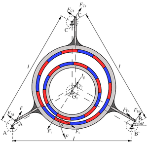
Figure 2 is the force analysis model of Figure 1.
Figure 2 TRMG force analysis model.
In Figure 2, crank AA', crank BB' and crank CC' respectively represent eccentric high-speed shaft 1, 2 and 3. Fr and Ft are the radial electromagnetic force and tangential electromagnetic force of low-speed permanent magnet ring and ring-plate permanent magnet ring respectively. , , , , and are the radial force and tangential force of each eccentric high-speed shaft acting on the ring-plate bearing seat hole through rolling bearing. is the inertial force on the ring-plate permanent magnet ring. is crank rotation time. is the rack spacing.
3.2 TRMG electromagnetic force analysis
Establish the low-speed permanent magnet ring section XO1Y rectangular coordinate system. Set up Is the included angle along the x-direction at a point on the circumference of the inner ring permanent magnet rotor surface. Set up is the air-gap magnetic density at any point on the surface of the low-speed permanent magnet ring, and are components along with the x and y directions respectively, and are components along with the tangential and radial directions respectively, then:
|
|
(1) |
In Equation (1), is the TRMG transmission ratio.
Set up the tangential and radial electromagnetic force of the unit area of the low-speed permanent magnet ring are and . According to the Maxwell stress tensor method, it can be:
|
|
(2) |
In Equation (2), is the permeability of vacuum.
Set up the tangential and radial electromagnetic force of the low-speed permanent magnet ring are and respectively, then:
|
|
(3) |
According to Equation (3), and can be obtained as long as the surface air-gap magnetic density of the low-speed permanent magnet ring is obtained.
By taking the torque of tangential electromagnetic force, the electromagnetic torque of the low-speed permanent magnet ring can be obtained:
|
|
(4) |
3.3 Force analysis of each shaft with TRMG single-shaft input
If crank BB' is used as the input shaft, and crank AA' and crank CC' are used as support shafts, the force model of each shaft is shown in Figure 3.
Figure 3. Force model of TRMG shafts.
In Figure 3, is input torque, and IAr, IAt, IBr, IBt, ICr, and ICt are the radial and tangential forces acting on A', B', and C' of the ring-plate permanent magnet ring through the rolling bearing, respectively.
The static equilibrium equations of ring-plate permanent magnet ring, input shaft B, and support shafts A and C can be obtained from the theoretical mechanical rigid body force and moment balance equations respectively.
|
|
(5) |
If , , and are set as the radial additional force acting on the ring-plate permanent magnet ring by the rolling bearing of each shaft respectively, then:
|
|
(6) |
In Equation (6), 1 and 2 are respectively the radial force of support shafts A, C and input shaft B acting on the ring-plate permanent magnet ring through the rolling bearing under the ideal condition, and:
|
|
(7) |
In Equation (7), the inertia force , where is the weight of ring-plate permanent magnet ring.
According to Equation (7), the difference between , , and are proportional to the additional force applied.
If the contact stiffness of the rolling bearings of input shaft and the support shafts is , and the ring-plate permanent magnet ring generates angle by the radial additional force is , then the coordination conditions of the body displacement and its deformation can be obtained:
|
|
(8) |
According to Equation (8), the difference between the tangential force of crank BB' (input shaft) and the tangential electromagnetic force of low-speed permanent magnet ring (output shaft) in TRMG can lead to deviation from the ideal state during the operation of ring-plate.
Combine Equation (8) with Equation (3) ~ Equation (7), it can be obtained:
|
|
(9) |
|
|
(10) |
|
|
(11) |
|
|
(12) |
|
|
(13) |
According to Equation (10), when the structural parameters of TRMG permanent magnets remain unchanged, is proportional to the input torque and inversely proportional to the eccentricity of the high-speed shaft .
It can be seen from Equation (11) ~ Equation (13):
(1) The radial force of each shaft in TRMG is composed of tangential and radial electromagnetic force of low-speed permanent magnet ring and the tangential force of input shaft.
(2) When is equal to 0° or 180°, that is, when the crank AA' and the crank BB' are collinear with the connecting rod AB, is larger than and , indicating that the crank CC' drives the crank AA' and the crank BB' to move through ring-plate and making them pass through the collinear position smoothly.
(3) Since the expressions of , and contain trigonometric functions of input tangential force and tangential electromagnetic force, the impact load of input shaft and support shafts can be reduced by reducing their amplitudes, to slow down the extrusion and elastic deformation caused by impact load and increase the service life of rolling bearings.
4. TRMG dynamic model simulation
To obtain the force relationship curve of each moving part in TRMG, Ansys Maxwell is used to analyzing the magnetic field force between the low-speed permanent magnet ring and the ring-plate permanent magnet ring, to determine the radial and tangential electromagnetic force in TRMG. and are then put into MATLAB force analysis program, and the force curve of each motion shaft is determined.
4.1 Analysis of TRMG electromagnetic characteristics
Set rated power is rated output speed of low-speed permanent magnet ring is , transmission ratio is , torque density is , flux leakage coefficient is 0.2. The static and dynamic electromagnetic fields that calculate the function of Ansys Maxwell are used to analyze the finite element structure of TRMG and TRMG parameters are optimized according to improved torque characteristics. Finally, TRMG electromagnetic model parameters as shown in Table 1 can be obtained.
Table 1. TRMG electromagnetic model parameters.
| Symbol | Description | Value (Unit) |
| Pole pairs of inner permanent magnet | 22 | |
| Pole pairs of outer permanent magnet | 23 | |
| Inner radius of outer yoke iron | 96(mm) | |
| Outer radius of outer permanent magnet ring | 100(mm) | |
| Inner radius of outer permanent magnet ring | 94(mm) | |
| Outer radius of inner permanent magnet ring | 90(mm) | |
| Inner radius of inner permanent magnet ring | 84(mm) | |
| style="border: 1pt solid black;text-align: center;"Outer radius of inner yoke iron | 88(mm) | |
| Inner yoke iron thickness | 15(mm) | |
| Outer yoke iron thickness | 15(mm) | |
| Eccentricity | 3(mm) | |
| Axial length | 30(mm) | |
| Magnetization | -890(kA/m) | |
| Vacuum permeability | 4π×10-7 |
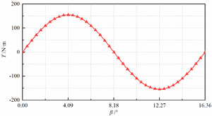
Figure 4 shows TRMG electromagnetic torque curve based on the parameters in Table 1 by ANSYS.
Figure 4. Relationship between and .
As can be seen from Figure 4, the electromagnetic torque curve of low-speed permanent magnet ring is a sine wave. When it rotates 1/2 and 3/2 magnetic pole angles, the maximum output electromagnetic torque is . In this paper, the load torque is 125N·m.
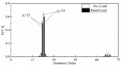
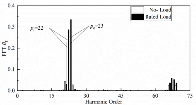
Figure 5 and Figure 6 show the harmonic comparison of radial and tangential air-gap magnetic density of TRMG under no-load and load after Fourier decomposition.
As can be seen from Figure 5, the radial air-gap flux density waveform of TRMG is mainly composed of 22nd harmonic and 23rd harmonic, among which the 23rd and 22nd harmonic of no-load (about 0.65t and 0.55t) are larger than the loaded harmonic (about 0.59t and 0.51t). As can be seen from Figure 6, the 23rd and 22nd harmonics (about 0.25t and 0.23t) of TRMG tangential air-gap flux density in no load are less than the loaded harmonics (about 0.34t and 0.29t).
Figure 5. The spectrum of radial electromagnetic force.
Figure 6. The spectrum of tangential electromagnetic force.
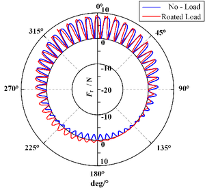
Combined with Equation (3) and Equation (4), the variation of radial electromagnetic force acting on low-speed permanent magnet ring with no-load and rated load can be obtained, as shown in Figure 7.
Figure 7. The distribution curve of radial electromagnetic force.
As can be seen from Figure 7, the positive direction of Fr deviates from the center of the circle, while the negative direction of points to the center of the circle. Therefore, the smaller side of the air-gap between permanent magnets attracts each other, while the larger side repays each other. The average radial electromagnetic force under no-load and rated load is 535N and 441N respectively. The tangential electromagnetic force is small at no-load, and most of the air-gap magnetic field generated by TRMG acts on the radial magnetic field force, making the radial magnetic field force larger at no-load.
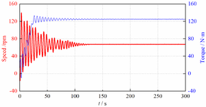
Figure 8 shows the dynamic characteristic curve of low-speed permanent magnet ring under rated load.
Figure 8. Dynamic characteristic of low-speed permanent magnet ring.
According to the transmission ratio and Maxwell stress tensor method, the input torque M=5.64N·m, and the tangential and radial electromagnetic force received by the low-speed permanent magnet ring is and respectively.
4.2 TRMG each shaft force analysis
Suppose that the force of shaft A, shaft B and shaft C on the ring-plate bearing hole through the rolling bearing is , and respectively, then:
|
|
(14) |
According to TRMG mechanical analysis model, TRMG dynamic force is analyzed in MATLAB, and and are replaced into the equation to obtain the change curves of force of input shaft and support shafts in Figure 9.
Figure 9. Change curves of FA, FB and FC under single shaft driving.
Figure 9 shows that:
(1) When the cranks rotate, the force of the input shaft and the support shafts change periodically, and the varying degree of support shaft A and C is the same. According to Equation (9), and are 0, shaft A and C are only TRMG connection structures, and both transmission process are the same, so the bearing force trends is the same.
(2) When the cranks rotate, the force of the input shaft and the support shafts can make fluctuate in addition to periodic change. For example, when , the change of produces fluctuation.
Because in Figure 2, when , crank BB' and crank CC' are collinear with connecting rod BC. At this time, due to is small and it fails to pass smoothly through the collinear position, resulting in the fluctuation of .
When , although the crank AA' and crank BB' are collinear with the connecting rod AB, is large at this time, which enables to pass through the collinear position smoothly, so does not fluctuate at this time. Similarly, the same is true for and fluctuations.
5. TRMG multi-shafts drive mode
Due to TRMG's low operating efficiency driven by a single shaft, the force range of the rolling bearing is large and has large fluctuations, leading to low service life. The power is input and studied by three cranks of TRMG at the same time.
5.1 Force analysis of TRMG with multi-shafts drive
Figure 10 is a schematic diagram of the force acting on each shaft in the multi-shafts drive.
Figure 10. TRMG force analysis under multi-shafts driving.
As can be seen from Figure 10, since the support cranks are changed to input cranks, the force between the input cranks is the same. At this time, the static balance equations of input crank AA', BB' and CC' are:
|
|
(15) |
|
|
(16) |
|
|
(17) |
|
|
(18) |
By comparing Equation (16) ~ Equation (18) and Equation (11) ~ Equation (13), it can be seen that the difference between TRMG tangential electromagnetic force and the input tangential force is reduced by using the multi-shafts drive, thus reducing the magnitude and amplitude of , and .
5.2 Force relationship curve of TRMG each shaft by multi-shafts
By substituting Equation (16) ~ Equation (18) into MATLAB transmission force analysis program, the force variation curves of input shafts A, B, and C shown in Figure 11 can be obtained.
Figure 11. Change curves of FA, FB and FC under multi-shafts driving.
In order to make a more intuitive comparison between the performance of multi-shafts and single shaft drive, the performance comparison of TRMG under multi-shafts and single shaft drive is shown in Table 2.
Table 2. Performance comparison of TRMG multi-shafts vs single shaft drive.
| Parameter Comparison | Single shaft drive | Multi-shafts drive |
| FA maximum value | 2.2(kN) | 1.6(kN) |
| FA oscillation wave | 0.5(kN) | 0(kN) |
| FB maximum value | 1.8(kN) | 2.1(kN) |
| FB oscillation wave | 0.3(kN) | 0(kN) |
| FC maximum value | 2.2(kN) | 1.6(kN) |
| FC oscillation wave | 0.5(kN) | 0(kN) |
From Table 2, after TRMG adopts multi-shafts drive when the cranks rotate, the force on shaft B increases slightly (0.3kN), but the force on shaft A and shaft C decreases significantly (0.6kN).As can be seen from Figure 10 and Figure 11, the force acting on each shaft is more average. This is because after changing to multi-shafts drive, the eccentric magnetic field force of the magnetic force device can be greatly reduced due to the symmetrical distribution of the magnetic force device of the input shafts relative to the TRMG, thus the force acting on each input shaft is more uniform and the stress environment of each shaft can be effectively alleviated.
In addition, the vibration of , , and is eliminated after changing to multi-shafts drive, and the vibration problem of each shaft is solved. Thus, the stress condition of rotary bearings can be significantly improved and their service life can be prolonged.
6. TRMG multibody dynamics analysis
To further verify the correctness of established TRMG torque balance equation and determine the feasibility of multi-shafts drive TRMG scheme, through ADAMS multi-body dynamics simulation software is used to analyze the values of , , and in multi-shafts drive TRMG, and the results are compared with the calculated data.
Table 3 shows the constraint allocation of mechanical devices in the TRMG multi-body dynamics simulation model.
Table 3. Constraint allocation of TRMG model.
| Part - Part | Constraint |
| Input shaft A- Ground | Rotating |
| Input shaft B- Ground | Rotating |
| Input shaft C- Ground | Rotating |
| Input shaft A- Ring-plate permanent magnet ring | Rotating |
| Input shaft B- Ring-plate permanent magnet ring | Rotating |
| Input shaft C- Ring-plate permanent magnet ring | Rotating |
| Low-speed permanent magnet ring - Output shaft | Fixed |
| Output shaft - Ground | Rotating |
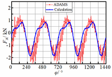
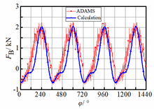
According to the analysis results of the TRMG dynamics model, input shafts A, B, and C are given input speed n=1200r/min, and the output shaft is given load torque of 124N·m.The multi-body dynamics simulation and analytical calculation data curves of the forces acting on input shafts A, B, and C are obtained, as shown in Figure 12.
| (a) (b) (c) |
Figure 12. FA, FB, FC theory and multi-body dynamics distribution curves.
As can be seen from Figure 12:
(1) When multi-body dynamics analysis of multi-shafts driven TRMG is adopted, the numerical changes of , , and tend to be more sinusoidal, and their results are always greater than those of analytical analysis.This is because the multi-body dynamic analysis needs to consider the material properties of the structure, the moment of inertia, the distribution of constraints, and other factors, and also takes the coupling relationship between components into account, which makes the running process of each shaft in the simulation more stable, and finally leads to the large results of , , and , and the changes tend to be more sinusoidal.
(2) When using the multi-body dynamic analysis and analytical analysis, the variation trend of FA, FB, and FC in the two analysis results is roughly the same, and the deviation of their amplitude is within a reasonable range (about 10%).Thus, it can be further confirmed that the established TRMG torque balance equation is correct.In addition, , , and of the two analyses all changed periodically without significant fluctuation, which confirmed the feasibility of a multi-shafts TRMG drive scheme.
7. Conclusions
(1) Combined of electromagnetism theory and rigid body statics theory, TRMG mechanical balance equation is established, and FEM and mathematical analytical method are combined to solve the force acting on each shaft, Finally, the validity of TRMG model is verified by multi-body dynamics method.
(2) Compared with the single-shaft drive mode, TRMG adopts multi-shafts drive, which can make the force on each drive shaft more even, eliminate the shock caused by the single-shaft drive, greatly improve the force condition of the rolling bearing, and prolong the service life of the rolling bearing.
(3) The established TRMG mathematical model has universality, which provides a certain mathematical basis for in-depth study of multi-shafts ring-plate transmission structure and magnetic gear structure with large torque.
Acknowledgments
This work was funded by the National Natural Science Foundation of China (Grant No.51375063), and also sponsored by the Natural Science Research Project of Liaoning Province Education Department (Grant No.JDL2020001) and partly funded by the Technological Innovation Research Foundation Project of Dalian (Grant No.2018J12SN071).
References
[1] Chen. Z. Y, Liu. Z. W., Wang. Z. D, and S. L. Guo, Three-ring type deceleration (or increase) transmission device, CN85106692,1987.
[2] SONG. Y, TIAN. G, ZHANG. J, LIU. M, and LIU. J Prediction for Dynamic Characteristics of Ring-Plate Planetary Indexing Cam Mechanism, Transactions of Tianjin University, 15,249-254,2009.
[3] B. YANG, Y. LIU, and Z. ZHONG, Experimental Research on Noise Source Identification of Ring-Plate Pin-Cycloid Planetary Reducer, ICLEM 2010: Logistics for Sustained Economic Development,1596-1601, 2010.
[4]. M. LIU, Y. SONG, C. ZHANG, and G. TIAN, Force Analysis of Rollers of Ring-plate-type Planetary Indexing Cam Mechanism, China Mechanical Engineering, 19(16),1912-1915,2008.
[5] M. A. Jafarizadeha, R. Hassannejadb, M. M. Ettefaghb, and S. Chitsazb, Asynchronous input gear damage diagnosis using time averaging and wavelet filtering,Mechanical Systems and Signal Processing, 22,172-201,2008.
[6] W. Q. Wang, F. Ismail, and M. F. Golnaraghi, Assessment of Gear Damage Monitoring Techniques Using Vibration Measurements, Mechanical Systems and Signal Processing, 15 (5), 905-922, 2001.
[7] J. H. Shin, and S. M. Kwon, On the lobe profile design in a cycloid reducer using instant velocity center, Mechanism and Machine Theory, 41,596-616,2006.
[8] W. Liu, T. Lin, and Y. Xie, Vibration Characteristic Analysis and Experimental Research of Double-ring Gear Reducer, China Mechanical Engineering, 20(10),1192-1196,2009.
[9] ZJSYZ. Ce, and M. Xianju, Statics Analysis of Three-ring Gear Reducer by Finite Element Method, Transactions of the Chinese Society for Agricultural Machinery, 38(3),141-143, 2007.
[10] J. Zhang, Y. M. Song, and C. Zhang, Elasto-dynamic Analysis of Ring-plate Gear Reducer with Small Tooth Number Difference, Journal of Mechanical Engineering, 44 (2), 118-123, 2008.
[11] ZCLLZ. Lei, and Y. Bin, Study on Double-crank Reducer with External Gear Board, Transactions of the Chinese Society for Agricultural Machinery, 39(8), 149-152, 2008.
[12] O. Molokanov, P. Dergachev, S. Dergachev, E. Kuznetsova, and P. Kurbatov, A Novel Double-Rotor Planetary Magnetic Gear, IEEE transactions on magnetics, 54 (11),1-5, 2018.
[13] Y. J. Ge, C. Y. Nie, and Q. Xin, A Three Dimensional Analytical Calculation of the Air-Gap Magnetic Field and Torque of Coaxial Magnetic Gears, Progress In Electromagnetics Researc, 131,391-407,2012.
[14] K. Davey, L. McDonald, and T. Hutson, Axial flux cycloidal magnetic gears, IEEE transactions on magnetics, 50 (4), 2014.
[15] Z. Deng, I. Nas, and M. J. Dapino, Torque Analysis in Coaxial Magnetic Gears Considering Nonlinear Magnetic Properties and Spatial Harmonics, IEEE Transactions on Magnetics, (2),1-11,2019.
Document information
Published on 09/09/22
Accepted on 29/08/22
Submitted on 07/02/22
Volume 38, Issue 3, 2022
DOI: 10.23967/j.rimni.2022.09.004
Licence: CC BY-NC-SA license
Share this document
Keywords
claim authorship
Are you one of the authors of this document?
