Palomaluna (talk | contribs) (Tag: Visual edit) |
Palomaluna (talk | contribs) (Tag: Visual edit) |
||
| (7 intermediate revisions by the same user not shown) | |||
| Line 1: | Line 1: | ||
| − | |||
| − | |||
| − | |||
| − | |||
| − | |||
| − | |||
| − | |||
| − | |||
| − | |||
| − | |||
| − | |||
| − | |||
| − | |||
| − | |||
| − | |||
| − | |||
| − | |||
| − | |||
| − | |||
| − | |||
| − | |||
| − | |||
| − | |||
| − | |||
| − | |||
| − | |||
| − | |||
| − | |||
| − | |||
| − | |||
| − | |||
| − | |||
| − | |||
| − | |||
| − | |||
| − | |||
| − | |||
| − | |||
| − | |||
| − | |||
| − | |||
| − | |||
| − | |||
| − | |||
| − | |||
| − | |||
| − | |||
| − | |||
| − | |||
| − | |||
| − | |||
| − | |||
| − | |||
| − | |||
| − | |||
| − | |||
| − | |||
| − | |||
| − | |||
| − | |||
| − | |||
| − | |||
| − | |||
| − | |||
| − | |||
| − | |||
| − | |||
| − | |||
| − | |||
| − | |||
| − | |||
| − | |||
==1 Introduction== | ==1 Introduction== | ||
| Line 77: | Line 5: | ||
Because of composite structural characteristics, damage occurrence is a major topic in the use of this type of materials [2]. As its use has rapidly increased in industry, the need of a reliable repair technology has arisen. For this reason, an intensive research is being carried out as a response to the industry demand. | Because of composite structural characteristics, damage occurrence is a major topic in the use of this type of materials [2]. As its use has rapidly increased in industry, the need of a reliable repair technology has arisen. For this reason, an intensive research is being carried out as a response to the industry demand. | ||
| − | As part of this research, it is important to take into account in service conditions because the adhesives that constitutes the composite patch matrix and bond the repaired structure, are susceptible to degradation providing | + | As part of this research, it is important to take into account in service conditions because the adhesives that constitutes the composite patch matrix and bond the repaired structure, are susceptible to degradation providing subsequent repair failure during operational life. Humidity and temperature are the most challenging threats in terms of environmental conditions, and their levels can be quite variable depending on many factors such as the location or the season. In order to validate the developed repair technologies it is important to take environmental influence into account, and reproduce these conditions by ageing the structures under controlled humidity and temperature conditions simulating the worst case scenario. |
There are different types of repair solutions currently being applied into the repair process of composite materials. Moreover, the sector is devoting great efforts in the research of new or improved repair concepts that could be applicable into existing structures. | There are different types of repair solutions currently being applied into the repair process of composite materials. Moreover, the sector is devoting great efforts in the research of new or improved repair concepts that could be applicable into existing structures. | ||
| Line 109: | Line 37: | ||
For the tension tests, specimens were prepared by bonding of glass fiber tabs. For this process, an epoxy adhesive was used and a careful surface preparation was followed in order to avoid premature failure during the test execution. | For the tension tests, specimens were prepared by bonding of glass fiber tabs. For this process, an epoxy adhesive was used and a careful surface preparation was followed in order to avoid premature failure during the test execution. | ||
| − | + | [[File:Review_185315623460_6009_Figura 1.PNG|center|350px]]<div class="center" style="width: auto; margin-left: auto; margin-right: auto;"> | |
| − | + | ||
| − | + | ||
| − | + | ||
| − | + | ||
| − | + | ||
| − | + | ||
| − | + | ||
| − | + | ||
| − | <div class="center" style="width: auto; margin-left: auto; margin-right: auto;"> | + | |
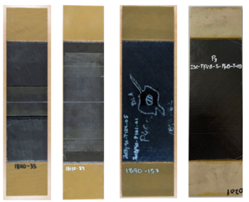
<span style="text-align: center; font-size: 75%;">'''Figure 1.''' a) and b) Thermoset specimens, total and partial repair configurations. c) and d) Thermoplastic specimens, reconsolidation and total patch pre-cure configurations</span></div> | <span style="text-align: center; font-size: 75%;">'''Figure 1.''' a) and b) Thermoset specimens, total and partial repair configurations. c) and d) Thermoplastic specimens, reconsolidation and total patch pre-cure configurations</span></div> | ||
| Line 128: | Line 47: | ||
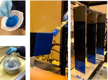
To execute this protection, a novel procedure was developed based on the application of non-porous silicone material with capability of adhesion to the area under protection, resistance of the environmental conditions, and debonding capacity after the process. So this material adheres perfectly to the specimens’ surface and it is also easily removable | To execute this protection, a novel procedure was developed based on the application of non-porous silicone material with capability of adhesion to the area under protection, resistance of the environmental conditions, and debonding capacity after the process. So this material adheres perfectly to the specimens’ surface and it is also easily removable | ||
| − | + | [[File:Review_185315623460_5894_Figure-02.JPG|center|350px]] | |
| − | + | ||
| − | + | ||
| − | + | ||
| − | + | ||
| − | + | ||
| − | + | ||
| − | + | ||
| − | + | ||
| − | + | ||
| − | + | ||
<div class="center" style="width: auto; margin-left: auto; margin-right: auto;"> | <div class="center" style="width: auto; margin-left: auto; margin-right: auto;"> | ||
<span style="text-align: center; font-size: 75%;">'''Figure 2.''' Specimen protection application process</span></div> | <span style="text-align: center; font-size: 75%;">'''Figure 2.''' Specimen protection application process</span></div> | ||
| Line 151: | Line 60: | ||
<div class="center" style="width: auto; margin-left: auto; margin-right: auto;"> | <div class="center" style="width: auto; margin-left: auto; margin-right: auto;"> | ||
| − | [[Image:Draft_Luna_627311235-image13-c.png| | + | [[Image:Draft_Luna_627311235-image13-c.png|500x500px]] </div> |
<span id='_Ref100133485'></span><div id="_Ref100133481" class="center" style="width: auto; margin-left: auto; margin-right: auto;"> | <span id='_Ref100133485'></span><div id="_Ref100133481" class="center" style="width: auto; margin-left: auto; margin-right: auto;"> | ||
| Line 170: | Line 79: | ||
{| class="formulaSCP" style="width: 100%; text-align: center;" | {| class="formulaSCP" style="width: 100%; text-align: center;" | ||
|- | |- | ||
| − | | | + | | |
| − | + | [[File:Review_185315623460_8080_Eq1.JPG|120x120px]] | |
| − | + | ||
| − | + | ||
| − | | | + | |
| style="width: 5px;text-align: right;white-space: nowrap;" | (1) | | style="width: 5px;text-align: right;white-space: nowrap;" | (1) | ||
|} | |} | ||
| Line 341: | Line 247: | ||
The acquisition equipment for performing the measurement of the strain gauges, the load and the position during the test execution is a Hottinger Bladwin MGCPlus. | The acquisition equipment for performing the measurement of the strain gauges, the load and the position during the test execution is a Hottinger Bladwin MGCPlus. | ||
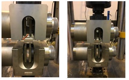
| − | Specific test tooling was designed for the development of this test campaign. The jaws used to fix the test specimen during the test execution are crucial to obtain accurate results, especially where test forces of over 50kN are required. Specimens are clamped directly by jaws prior to the start of the tests. <span id='cite-_Ref97711863'></span>[[#_Ref97711863|Figure 4]] shows the designed and manufactured jaws used for the tension tests. | + | Specific test tooling was designed for the development of this test campaign. The jaws used to fix the test specimen during the test execution are crucial to obtain accurate results, especially where test forces of over 50kN are required. Specimens are clamped directly by jaws prior to the start of the tests. <span id='cite-_Ref97711863'></span>[[#_Ref97711863|Figure 4]] shows the designed and manufactured jaws used for the tension tests.<div id="_Ref97711863" class="center" style="width: auto; margin-left: auto; margin-right: auto;">[[File:Figure-04.jpg|centre]]<span style="text-align: center; font-size: 75%;">'''Figure 4.''' Clamping jaws for tension tests</span></div> |
| − | + | ||
| − | + | ||
| − | + | ||
| − | + | ||
| − | + | ||
| − | + | ||
| − | + | ||
| − | + | ||
| − | <div id="_Ref97711863" class="center" style="width: auto; margin-left: auto; margin-right: auto;"> | + | |
| − | <span style="text-align: center; font-size: 75%;">'''Figure 4.''' Clamping jaws for tension tests</span></div> | + | |
====2.3.3.1 Innovative monitoring system==== | ====2.3.3.1 Innovative monitoring system==== | ||
| Line 360: | Line 256: | ||
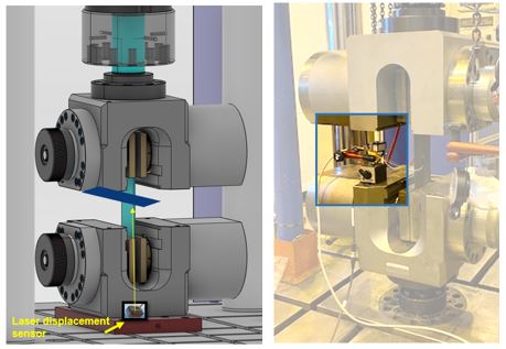
In <span id='cite-_Ref97711563'></span>[[#_Ref97711563|Figure 5]], the laser displacement sensor position is displayed. The sensor is placed at the base surface of the test machine and the receptor (pictured in blue in the figure) is positioned at the surface of the upper jaw. | In <span id='cite-_Ref97711563'></span>[[#_Ref97711563|Figure 5]], the laser displacement sensor position is displayed. The sensor is placed at the base surface of the test machine and the receptor (pictured in blue in the figure) is positioned at the surface of the upper jaw. | ||
| − | + | [[File:Figure-05.jpg|centre]] | |
| − | + | ||
| − | + | ||
| − | + | ||
| − | + | ||
| − | + | ||
| − | + | ||
| − | + | ||
<div id="_Ref97711563" class="center" style="width: auto; margin-left: auto; margin-right: auto;"> | <div id="_Ref97711563" class="center" style="width: auto; margin-left: auto; margin-right: auto;"> | ||
<span style="text-align: center; font-size: 75%;">'''Figure 5.''' Laser displacement sensor configuration in tension test </span></div> | <span style="text-align: center; font-size: 75%;">'''Figure 5.''' Laser displacement sensor configuration in tension test </span></div> | ||
| Line 522: | Line 411: | ||
The typical failure observed for patch repair configurations clearly showed that the failure of the test specimen initiated as a result of an adhesive failure. <span id='cite-_Ref99440264'></span>[[#_Ref99440264|<span style="text-align: center; font-size: 75%;">Figure 6</span>]] illustrates the failure mode of the patched test specimens. | The typical failure observed for patch repair configurations clearly showed that the failure of the test specimen initiated as a result of an adhesive failure. <span id='cite-_Ref99440264'></span>[[#_Ref99440264|<span style="text-align: center; font-size: 75%;">Figure 6</span>]] illustrates the failure mode of the patched test specimens. | ||
| − | + | [[File:Review_185315623460_6520_Figure-06.JPG|center|350px]] | |
| − | + | ||
| − | + | ||
| − | + | ||
| − | | | + | |
| − | + | ||
| − | + | ||
| − | + | ||
<div id="_Ref99440264" class="center" style="width: auto; margin-left: auto; margin-right: auto;"> | <div id="_Ref99440264" class="center" style="width: auto; margin-left: auto; margin-right: auto;"> | ||
<span style="text-align: center; font-size: 75%;">'''Figure 6.''' Typical failure mode for patch repair test specimens</span></div> | <span style="text-align: center; font-size: 75%;">'''Figure 6.''' Typical failure mode for patch repair test specimens</span></div> | ||
Nevertheless, on the reconsolidation specimens the failure occurred as a result of fiber breakage which started in the center of the test specimen where the reconsolidation took place during the repair process. In this area, the fibers were broken and repaired so a greater concentration of stresses enable the failure occurrence in this area. Because of greater rigidity is attributed to the 0º layers of the laminate, the fibers orientated in this direction were the first to fail, producing a failure perpendicular to the 0º direction later reoriented to the layers at ± 45º direction. <span id='cite-_Ref99446224'></span>[[#_Ref99446224|Figure 7]] illustrates the failure mode of this type of test specimens. | Nevertheless, on the reconsolidation specimens the failure occurred as a result of fiber breakage which started in the center of the test specimen where the reconsolidation took place during the repair process. In this area, the fibers were broken and repaired so a greater concentration of stresses enable the failure occurrence in this area. Because of greater rigidity is attributed to the 0º layers of the laminate, the fibers orientated in this direction were the first to fail, producing a failure perpendicular to the 0º direction later reoriented to the layers at ± 45º direction. <span id='cite-_Ref99446224'></span>[[#_Ref99446224|Figure 7]] illustrates the failure mode of this type of test specimens. | ||
| − | + | [[File:Figure-07.jpg|centre]] | |
| − | + | ||
| − | + | ||
| − | + | ||
| − | + | ||
| − | + | ||
| − | + | ||
| − | + | ||
<div id="_Ref99446224" class="center" style="width: auto; margin-left: auto; margin-right: auto;"> | <div id="_Ref99446224" class="center" style="width: auto; margin-left: auto; margin-right: auto;"> | ||
<span style="text-align: center; font-size: 75%;">'''Figure 7. '''Typical failure mode for reconsolidation specimens</span></div> | <span style="text-align: center; font-size: 75%;">'''Figure 7. '''Typical failure mode for reconsolidation specimens</span></div> | ||
| Line 625: | Line 500: | ||
<div class="center" style="width: auto; margin-left: auto; margin-right: auto;"> | <div class="center" style="width: auto; margin-left: auto; margin-right: auto;"> | ||
| − | [[Image:Draft_Luna_627311235-image22.png | + | [[Image:Draft_Luna_627311235-image22.png]] </div> |
<div id="_Ref102118276" class="center" style="width: auto; margin-left: auto; margin-right: auto;"> | <div id="_Ref102118276" class="center" style="width: auto; margin-left: auto; margin-right: auto;"> | ||
| Line 635: | Line 510: | ||
For these specimens, no damage progression was observed. <span id='cite-_Ref102120023'></span>[[#_Ref102120023|Figure 9]] depicts the obtained C-Scans for the ISC-TP2B-F-ReB test specimen. | For these specimens, no damage progression was observed. <span id='cite-_Ref102120023'></span>[[#_Ref102120023|Figure 9]] depicts the obtained C-Scans for the ISC-TP2B-F-ReB test specimen. | ||
| − | + | [[File:Draft_Luna_627311235-image23.png|centre]] | |
| − | [[ | + | |
<div id="_Ref102120023" class="center" style="width: auto; margin-left: auto; margin-right: auto;"> | <div id="_Ref102120023" class="center" style="width: auto; margin-left: auto; margin-right: auto;"> | ||
| Line 647: | Line 521: | ||
Being noted that the paper has been focused to provide some enhancements in different techniques around methodologies to be applied on coupon testing, results regarding repair test program are used to substantiate testing methodology. | Being noted that the paper has been focused to provide some enhancements in different techniques around methodologies to be applied on coupon testing, results regarding repair test program are used to substantiate testing methodology. | ||
| − | To complement the overall view, results on repairs conceptual studies carried on different types of substrate materials have been presented. | + | To complement the overall view, results on repairs conceptual studies carried on different types of substrate materials have been presented. |
| + | |||
| + | The full set of results that has been presented is pending on deeper assessment. Therefore, the overview that has been provided should be considered as a good trend although provisional in regard to the final conclusion of the research to be carried on. | ||
| − | + | In relation with the conditioning process of the test specimens, it was noted that the protection stage that was performed, successfully achieved its preliminary objective of avoiding humidity from entering through the edges. The protection that resulted from the newly developed method remained intact throughout the entire conditioning process, and was easily removable prior to the execution of the tests. | |
| − | + | Regarding the test results, the following conclusions have been found: | |
For the thermoplastic test specimens it is noted that the behavior of patched and reconsolidated test specimens strongly varies for the static and fatigue tests. Meanwhile patched elements show a better strength performance, reconsolidated repairs evidence much better fatigue behavior under tension loads keeping the residual strength at the end of the life within a very good percentage with the average strength capability. | For the thermoplastic test specimens it is noted that the behavior of patched and reconsolidated test specimens strongly varies for the static and fatigue tests. Meanwhile patched elements show a better strength performance, reconsolidated repairs evidence much better fatigue behavior under tension loads keeping the residual strength at the end of the life within a very good percentage with the average strength capability. | ||
| Line 657: | Line 533: | ||
Thermoset overall repair behavior show much less performance that thermoplastics for all the repairs concepts being tested. | Thermoset overall repair behavior show much less performance that thermoplastics for all the repairs concepts being tested. | ||
| − | Finally, this study is focused on the selection of the most efficient method regarding the repair | + | Finally, this study is focused on the selection of the most efficient method regarding the repair of thermoplastic and thermoset specimens, and an up-scaling of the technology at component and structural level of higher geometrical complexity will be performed in light of the obtained results. |
==Acknowledgments== | ==Acknowledgments== | ||
Latest revision as of 13:10, 2 June 2022
1 Introduction
The use of composite materials has grown drastically in the past few decades due to their advantageous mechanical properties, low weight and the maturation of industrial processes. The aerospace industry is among the sectors in which composite materials have higher application rates. This industry has been for a long time transitioning towards the use of composite materials, as a greater relation of weight to mechanical properties can be achieved when compared to the use of metallic materials [1]. Thus, contributing towards a cleaner and more sustainable air transport healthier environment.
Because of composite structural characteristics, damage occurrence is a major topic in the use of this type of materials [2]. As its use has rapidly increased in industry, the need of a reliable repair technology has arisen. For this reason, an intensive research is being carried out as a response to the industry demand.
As part of this research, it is important to take into account in service conditions because the adhesives that constitutes the composite patch matrix and bond the repaired structure, are susceptible to degradation providing subsequent repair failure during operational life. Humidity and temperature are the most challenging threats in terms of environmental conditions, and their levels can be quite variable depending on many factors such as the location or the season. In order to validate the developed repair technologies it is important to take environmental influence into account, and reproduce these conditions by ageing the structures under controlled humidity and temperature conditions simulating the worst case scenario.
There are different types of repair solutions currently being applied into the repair process of composite materials. Moreover, the sector is devoting great efforts in the research of new or improved repair concepts that could be applicable into existing structures.
2 Materials and methods
2.1 Materials description and manufacturing process
Most common carbon fibre reinforced polymers (CFRP) are classified into thermoplastic (TP) or thermoset (TS) depending on the nature of the resin of the matrix used for bonding the different layers of carbon fibres.
In this work some mechanical characteristics of both types of materials repairs have been investigated to get an idea of their incidence in the recovery of structural performance.
The repair typology depends among other factors on the extent of the damage as well as the certification requirements of the structure. In a repaired laminate different materials are used depending on the type of repair configuration to be performed. In a patch repair three materials can be observed; the repair material (both fiber format tape or fabric and same or compatible resin), the base laminate and the bonding agent (bolts, rivets, adhesive or a combination of them). However, in an infusion repair or a cobonded repair where no patch is applied to the structure, the materials that are identified are the parent material and the resin to be infused or consolidated.
The thermoplastic laminates have been manufactured by oven consolidation. Different thicknesses of laminates were manufactured. The thinner laminate named 2B has a nominal thickness of between 2 and 3 mm, whereas the thicker laminate, named 4B has a thickness between 4 and 5 mm. The laminates have a simmetrical stacking sequence combining layers at 45º, 90º and 0º.
The thermoset laminates have been manufactured by the vacuum assisted process (VAP) with two different material thickness. On one hand the thinner laminate 2B with thickness between 2 and 3 mm, and the thicker Called 3B with thickness between 3 and 4 mm.
Different repair configurations have been performed on the manufactured lamintes. The implemented repair configurations for the thermoplastic material foresees two possible process to get repair implementation: induction and back-up heating techniques. Thermoset material repairs explore different techniques to implement the repair concept being handled. Furthermore, for each of the test specimens except for the reconsolidation specimens, the repairs where implemented partially and totally throughout the thickness.
The repair program research deals with activity carried out into PROSOLTERM (MINECO), developed under the guideline of ADS and FIDAMC as main contributor to implement repairs at different structural levels. Both type of laminates, thermoset and termplastic, have been manufactured and different kinds of repairs were executed by FIDAMC.
The tension flat specimens present a rectangular geometry with a length of approximately 400 mm and a width of 100 mm.
2.2 Specimen preparation
2.2.1 Specimen extraction from manufactured panels
The above mentioned materials were manufactured in panels from which the test specimens were extracted. In the extraction process, a water-cooled diamond saw was used to avoid local heating of the specimens, and special care was taken to ensure that the fiber orientation was maintained with respect to the reference edges. Non-destructive inspections were performed after specimen extraction to verify no damage was introduced during this process.
For the tension tests, specimens were prepared by bonding of glass fiber tabs. For this process, an epoxy adhesive was used and a careful surface preparation was followed in order to avoid premature failure during the test execution.
2.2.2 Specimen protection prior to the conditioning process
Prior to the conditioning process, specimens are protected to avoid adhesive degradation of those areas in which moisture absorption mechanism does not appear in operation conditions as the full aircraft structure is only in contact with moisture along the skin surface and not through the laminate edges. Subsequently, a protection strategy was designed to cover two main areas: (1) tabs protection to prevent humidity from degrading the adhesive that bond the tabs to the surface of the test specimen, (2) edges protection to simulate the working conditions of the specimen and prevent the humidity from entering through these areas. For the purpose of comparing the travelers to the specimens, the edges of the travelers where protected as well.
To execute this protection, a novel procedure was developed based on the application of non-porous silicone material with capability of adhesion to the area under protection, resistance of the environmental conditions, and debonding capacity after the process. So this material adheres perfectly to the specimens’ surface and it is also easily removable
2.2.3 Specimen instrumentation
Tension flat coupons have been instrumented following two different configurations, depending on the type of repair performed on each specimen.
For the set of specimens presenting a stepped repair configuration, the instrumentation consists of two strain gauges positioned back-to-back in the middle section of the specimen.
For the set of reconsolidation specimens, the strain gauge configuration was modified in order to obtain a reliable measurement, as the induced damage and subsequent repair was performed in the center of the specimen. For this repair configuration the strain gauges position followed the sketch depicted in Figure 3.
2.3 Test description and set-up
2.3.1 Conditioning of test specimens
Normally, in order to quantify the effect of ageing with respect to mechanical properties, the specimens must be exposed to humidity and high temperature in a climatic chamber. Humidity-aged specimens typically use accelerated conditioning to simulate the long-term exposure to humid air and establish a moisture saturation of the material. According to EN 2823 [3], accelerated conditioning of the specimens until moisture equilibrium is achieved at (85% +5/-1) relative humidity and (70 ± 2) °C.
Once the specimens have reached the moisture equilibrium, they shall be tested within 4 hours of removal from the conditioning chamber.
ASTM D 5229 [4] and SACMA SRM 11 [5] provide general guidelines regarding environmental conditioning and moisture absorption.
These specifications detail the different methods for determining the effect of exposure to a humid atmosphere on both the physical and mechanical characteristic of composite materials, and different end-of-conditioning criteria are established. For the purpose of the conditioning process followed for these tests, the equilibrium equation is the following:
| (1) |
Where,
W: traveler weight
i: value of the current week
i-1: value of the previous week
b: initial reference value
Conditioning is considered to have ended when three consecutive weights performed in 168h intervals meet the criteria of equation (1).
This conditioning process has been followed for all test series except for the thermoset 2B total repair configurations, for which an accelerated conditioning process by immersion was performed. The reason behind the selection of this alternative conditioning process was to obtain preliminary results in order to determine which repair concept was more efficient and be able to implement it in the subsequent test campaigns as this process is faster. For this conditioning, specimens were as well protected and immersed in a water bath with temperature control set in 70ºC during 15 days.
2.3.2 Tension tests description
Static and fatigue tension tests have been carried out on flat coupons in order to determine the tensile mechanical properties of the laminates, and more specifically, on how the repair concepts introduced in each of the laminates affect their mechanical properties. Reference standards that have been followed for these test are ASTM D3039/D3039M [6] for the static tension tests and ASTM D3479/D3479M [7] for the fatigue tension tests.
Table 1 displays the full set of performed tests, with the test nomenclature and repair description (partial (P), total (T) and type), as well as the number of tests performed for each configuration.
| Test Identification | Static tests
X=S |
Fatigue tests
X=F |
Repair Description | |
| P | T | |||
| LRI-TS2B-X-REF | 3 | - | Reference | |
| LRI-TS2B-X-Adh | 3 | 3 | - | Prepreg patch |
| LRI-TS2B-X-RI | 3 | 3 | - | Dry patch |
| LRI-TS2B-X-RI+A | 3 | 3 | - | Hybrid |
| LRI-TS3B-X-REF | 3 | - | Reference | |
| LRI-TS3B-X-Adh | 3 | 3 | - | Prepreg patch |
| LRI- TS3B -X-RI | 3 | 3 | - | Dry patch |
| LRI-TS3B-X-RI+A | 3 | 3 | - | Hybrid |
| ISC-TP2B-X-REF | 3 | - | Reference | |
| ISC-TP4B-X-REF | 3 | - | Reference | |
| ISC-TP2B-X-ReB | 3 | - | Reconsolidation | |
| ISC-TP4B-X-ReB | 3 | 3 | Reconsolidation | |
| ISC-TP2B-X-PpB | 3 | 3 | 3 | Patch pre-cured |
| ISC-TP4B-X-PpB | 3 | 3 | 3 | Patch pre-cured |
Prior to the executions of the tests, specimens undergo a quality control process that comprises the dimensional control, visual inspection, and ultrasound inspection of both the manufactured panels, the tests specimens and the tap bonding.
2.3.3 Tension tests set-up
Static tension tests were performed on a 500kN universal test machine manufactured by IBERTEST. The model of the test machine is UFIB-1000E with serial number 112521. A 500kN load cell has been used to measure the applied load.
Fatigue tension tests were performed after static test in order to determine the failure load to establish the test parameters. For the execution of these tests a 1MN load cell was used in the INSTRON 8806 test machine.
The nominal number of cycles planned for all the tests specimens prior to the execution of the residual strength test was set on 180.000 cycles. The test frequency was set on 5Hz and the test control parameter was the test load.
The maximum and minimum fatigue loads are calculated as shown in equations 2 and 3.
|
|
(2) |
|
|
(3) |
|
|
(4) |
The acquisition equipment for performing the measurement of the strain gauges, the load and the position during the test execution is a Hottinger Bladwin MGCPlus.
2.3.3.1 Innovative monitoring system
For the purpose of obtaining an accurate measurement of the specimen displacement during the execution of the tests, a high performance distance sensor known as laser displacement transducer was used. A higher accuracy is obtained since it avoids the error coming from the adjustments of the test machine in the displacement recording.
The sensor used in this tests is the optoNCDT1420, which offers a unique combination of speed, size and performance. Among the advantages that this sensor offers is that because of its small size it can be installed in small spaces.
In Figure 5, the laser displacement sensor position is displayed. The sensor is placed at the base surface of the test machine and the receptor (pictured in blue in the figure) is positioned at the surface of the upper jaw.
2.3.4 C-Scan inspections during fatigue tests
As non-destructive testing technique, ultrasonic inspections were performed to gather relevant information about the internal structure of the test specimens during the fatigue tests.
For obtaining a full visualization of the surface of the test specimens, the C-Scan mapping method was used. The main advantage of this method when compared to other common ultrasonic methods such as A-Scan, is that the C-Scan ultrasonic testing displays the data in high resolution along with different color patterns that allows easy and accurate detection flaws in the components. C-Scan can operate in amplitude or depth base modes. For the inspection of the fatigue test specimens, amplitude base C-Scan was performed.
The equipment used for these inspections is the Omniscan MX along with the Phase array UT transducer 5L 64-NW1.
3 Results
3.1 Static tension tests
For the static tension tests, test specimens were positioned in the test machine and subjected to monotonic tension loading until failure. Table 2 shows the standardized mean value of failure load of the static test results for all test series. This is the percentage of strength recovery achieved with respect to the original non-damaged laminate (REF = 100%).
| Static tests (H/W) | Standarized
value (%) |
Standard
deviation |
CV(%) | |
| Thermoplastic (2B) | PpB-P | 82% | 1.69 | 1% |
| PpB-T | 70% | 6.23 | 3% | |
| ReB | 54% | 9.79 | 7% | |
| REF | 100% | 5.05 | 2% | |
| Thermoplastic (4B) | PpB-P | 78% | 11.79 | 4% |
| PpB-T | 73% | 6.36 | 2% | |
| ReB | 60% | 18.04 | 7% | |
| REF | 100% | 7.58 | 2% | |
| Thermoset (2B) |
Adh - P | 47% | 2.63 | 2% |
| RI+A-P | 53% | 5.30 | 4% | |
| RI-P | 42% | 11.85 | 10% | |
| Adh - T | 46% | 2.28 | 2% | |
| RI+A-T | 46% | 10.59 | 8% | |
| RI-T | 37% | 4.31 | 4% | |
| REF | 100% | 2.44 | 1% | |
| Thermoset (3B) |
Adh - P | 66% | 0.67 | 0% |
| RI+A-P | 70% | 1.34 | 1% | |
| RI-P | 57% | 4.29 | 3% | |
| Adh - T | 70% | 1.89 | 1% | |
| RI+A-T | 66% | 4.84 | 3% | |
| RI-T | 58% | 4.01 | 3% | |
| REF | 100% | 3.56 | 2% | |
As it can be extracted from the standardized test results, for the thermoplastic test specimens, the patched repair configuration reached higher failure loads than the reconsolidation test specimens for both the 2B and the 4B thicknesses.
For the thermoset test specimens the results show that the test specimens having greater thickness achieved better strength recovery than thinner elements. Moreover, for both the 2B and 3B, total and partial configurations, results from the pre-preg and the hybrid repair configuration were similar, and a greater variation could be observed for the resin infusion repair configuration.
Another relevant aspect is to study the failure mode of the tested specimens to determine whether the failure occurred as a consequence of debonding of the patch, or adhesive failure during the test execution or as a consequence of fiber breakage or cohesive failure.
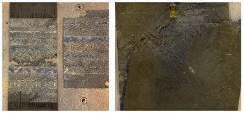
The typical failure observed for patch repair configurations clearly showed that the failure of the test specimen initiated as a result of an adhesive failure. Figure 6 illustrates the failure mode of the patched test specimens.
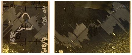
Nevertheless, on the reconsolidation specimens the failure occurred as a result of fiber breakage which started in the center of the test specimen where the reconsolidation took place during the repair process. In this area, the fibers were broken and repaired so a greater concentration of stresses enable the failure occurrence in this area. Because of greater rigidity is attributed to the 0º layers of the laminate, the fibers orientated in this direction were the first to fail, producing a failure perpendicular to the 0º direction later reoriented to the layers at ± 45º direction. Figure 7 illustrates the failure mode of this type of test specimens.
3.2 Fatigue tension tests
Table 3 shows the obtained results for some of the TP specimens and repair configurations of the fatigue tension tests that have been performed providing maximum spectrum load dependent on correspondent strength result on the same type of repair configuration.
| Fatigue tests H/W | Number of cycles | Average | Standard deviation | CV (%) |
| ISC-TP2B-ReB | 180000 | 180000.0 | 0 | 0 |
| 180000 | ||||
| 180000 | ||||
| ISC-TP2B-PpB-T | 36750 | 37633.3 | 1125.1 | 3 |
| 38900 | ||||
| 37250 | ||||
| ISC-TP4B-PpB-T | 6000 | 11000 | 11357.8 | 103 |
| 3000 | ||||
| 24000 |
Fatigue test results of TP4B coupons anticipate high level of variability that need to be deeply understood.
For the reconsolidation test specimens that reached the established 180000 cycles, a residual strength test was performed. Table X displays the results obtained with the execution of these tests.
| Residual stregth tests (H/W) | Standarized
value (%) | |
| ReB | Specimen 1 | 93% |
| Specimen 2 | 90% | |
| Specimen 3 | 98% | |
Additionally, for each of the test series a number of C-Scan inspections were planned in order to find out the evolution of the damage after each set of test cycles.
For the thermoplastic patched tests specimens, it was expected that none of them reached the 180.000 cycles. For that reason, inspections after each 15.000 cycles were planned and performed.
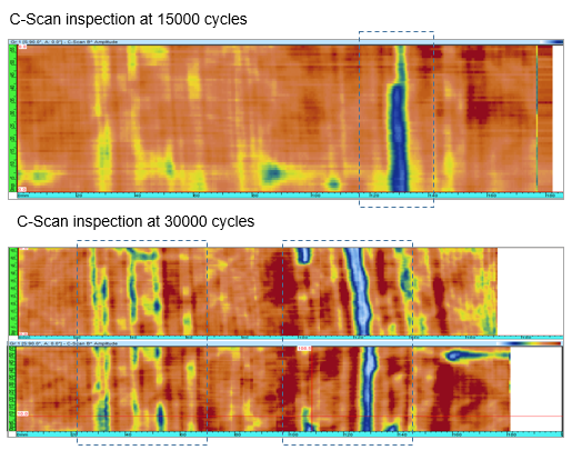
In Figure 8, damage progression for the ISC-TP2B-F-PpB-T specimen is observed.
In the upper figure, which shows the inspection performed at 15.000 cycles, a first indication is observed. In the second inspection performed at 30.000 cycles, a greater number of indications appeared. These indications are marked with a rectangle in the figure, to differentiate them from the rest of indications caused by the back wall eco loss.
For the thermoplastic reconsolidation tests specimens the inspection plan contemplated a fully inspected test specimen and the rest were partially inspected. The fully inspected test specimen underwent inspections at 15.000, 30.000, 45.000, 60.000, 90.000, 120.000, 150.000 and 180.000 cycles. For the partially inspected test specimens, the inspections took place at 15.000, 30.000, 60.000, 120.000 and 180.000 cycles.
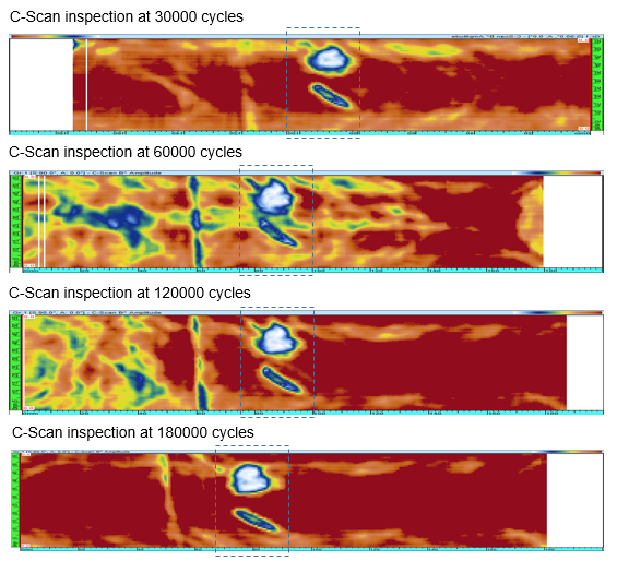
For these specimens, no damage progression was observed. Figure 9 depicts the obtained C-Scans for the ISC-TP2B-F-ReB test specimen.
In Figure 9, two main indications appear. On one hand there is the indication of the impacted area, which remained with the same dimensions during the entire tests. On the other hand there is another indication of a defect that is also present from the beginning of the inspections. Moreover, a third indication appears from the 120.000 and 180.000 test cycles inspections. This indication is a delamination is located at 0.5 mm of the impacted area, and remains with the same dimensions for both test cycles.
4 Conclusions
Being noted that the paper has been focused to provide some enhancements in different techniques around methodologies to be applied on coupon testing, results regarding repair test program are used to substantiate testing methodology.
To complement the overall view, results on repairs conceptual studies carried on different types of substrate materials have been presented.
The full set of results that has been presented is pending on deeper assessment. Therefore, the overview that has been provided should be considered as a good trend although provisional in regard to the final conclusion of the research to be carried on.
In relation with the conditioning process of the test specimens, it was noted that the protection stage that was performed, successfully achieved its preliminary objective of avoiding humidity from entering through the edges. The protection that resulted from the newly developed method remained intact throughout the entire conditioning process, and was easily removable prior to the execution of the tests.
Regarding the test results, the following conclusions have been found:
For the thermoplastic test specimens it is noted that the behavior of patched and reconsolidated test specimens strongly varies for the static and fatigue tests. Meanwhile patched elements show a better strength performance, reconsolidated repairs evidence much better fatigue behavior under tension loads keeping the residual strength at the end of the life within a very good percentage with the average strength capability.
Thermoset overall repair behavior show much less performance that thermoplastics for all the repairs concepts being tested.
Finally, this study is focused on the selection of the most efficient method regarding the repair of thermoplastic and thermoset specimens, and an up-scaling of the technology at component and structural level of higher geometrical complexity will be performed in light of the obtained results.
Acknowledgments
This project has received funding from the Clean Sky 2 Joint Undertaking (JU) under grant agreement No 864158. The JU receives support from the European Union’s Horizon 2020 research and innovation programme and the Clean Sky 2 JU members other than the Union.
The authors would like to express their gratitude to FADA-CATEC for the support provided with the inspection process during the execution of the tests.
References
[1] Hiken, A. (2018). The evolution of the composite fuselage: A manufacturing perspective. In Aerospace Engineering. IntechOpen.
[2] Katnam, K. B., Da Silva, L. F. M., & Young, T. M. (2013). Bonded repair of composite aircraft structures: A review of scientific challenges and opportunities. Progress in Aerospace Sciences, 61, 26-42.
[3] EN 2823. Aerospace series - Fibre reinforced plastics - Determination of the effect of exposure to humid atmosphere on physical and mechanical characteristics.
[4] D 5229/D 5229M – 92. Standard Test Method for Moisture Absorption Properties and Equilibrium Conditioning of Polymer Matrix Composite Materials.
[5] SRM 11R-94. Environmental Conditioning of Composite Test Laminates.
[6] ASTM D3039/D3039M. Standard Test Method for Tensile Properties of Polymer Matrix Composite Materials.
[7] ASTN D3479/D3479M. Standard Test Method for Tension-Tension Fatigue of Polymer Matrix Composite Materials.
Document information
Published on 16/10/22
Accepted on 20/06/22
Submitted on 29/04/22
Volume 07 - COMUNICACIONES MATCOMP21 (2022), Issue Núm. 2 - Aplicaciones Industriales - Caracterización, 2022
DOI: 10.23967/r.matcomp.2022.10.005
Licence: Other
Share this document
claim authorship
Are you one of the authors of this document?
