| (3 intermediate revisions by the same user not shown) | |||
| Line 199: | Line 199: | ||
{| style="text-align: center; margin:auto;" | {| style="text-align: center; margin:auto;" | ||
|- | |- | ||
| − | | <math>M_e=q_dScC_{MAC}+q_dS\left[\frac{\partial C_L}{\partial \alpha }({\alpha }_0+ \theta )\right]e</math> | + | | <math>M_e=q_dScC_{MAC}+q_dS\left[\displaystyle\frac{\partial C_L}{\partial \alpha }({\alpha }_0+ \theta )\right]e</math> |
|} | |} | ||
| style="width: 5px;text-align: right;white-space: nowrap;" | (10) | | style="width: 5px;text-align: right;white-space: nowrap;" | (10) | ||
|} | |} | ||
| − | + | where <math>q_d</math> is dynamic pressure, <math>S</math> is airfoil area, <math>c</math> is cross section chord, <math>C_{MAC}</math> is moment coefficient, <math>\frac{\partial C_L}{\partial \alpha }</math> is slope of lift curve, while <math>e</math> is the distance between stiffness center and aerodynamic center. | |
| − | + | ||
Constraints of the airfoil are applied by two springs. Equilibrium equation of aerodynamic moment and spring elastic moment is written as | Constraints of the airfoil are applied by two springs. Equilibrium equation of aerodynamic moment and spring elastic moment is written as | ||
| Line 219: | Line 218: | ||
|} | |} | ||
| − | + | where <math>k_{\alpha }</math> is spring elastic coefficient. Torsion angle <math>\theta </math> can be obtained and written as | |
| − | + | ||
{| class="formulaSCP" style="width: 100%; text-align: center;" | {| class="formulaSCP" style="width: 100%; text-align: center;" | ||
| Line 227: | Line 225: | ||
{| style="text-align: center; margin:auto;" | {| style="text-align: center; margin:auto;" | ||
|- | |- | ||
| − | | <math>\theta =\frac{\frac{q_dS}{k_{\alpha }}(e\frac{\partial C_L}{\partial \alpha }{\alpha }_0+cC_{MAC})}{1-\frac{q_deS}{k_{\alpha }}\frac{\partial C_L}{\partial \alpha }}</math> | + | | <math>\theta =\displaystyle\frac{\displaystyle\frac{q_dS}{k_{\alpha }}(e\displaystyle\frac{\partial C_L}{\partial \alpha }{\alpha }_0+cC_{MAC})}{1-\displaystyle\frac{q_deS}{k_{\alpha }}\displaystyle\frac{\partial C_L}{\partial \alpha }}</math> |
|} | |} | ||
| style="width: 5px;text-align: right;white-space: nowrap;" | (12) | | style="width: 5px;text-align: right;white-space: nowrap;" | (12) | ||
| Line 233: | Line 231: | ||
| − | When the denominator | + | When the denominator in Equation (12) equals to zero, torsion angle drives to infinite. By now, the wing is in a divergent state. And divergent velocity <math>V_D</math> can be written as |
{| class="formulaSCP" style="width: 100%; text-align: center;" | {| class="formulaSCP" style="width: 100%; text-align: center;" | ||
| Line 281: | Line 279: | ||
</div> | </div> | ||
| − | and design variable <math>X_L\leq X\leq X_U</math>, <math>X={\left(X_1,X_2,\cdots ,X_n\right)}^T</math>. | + | and design variable |
| + | <div class="center" style="text-align:center;"> | ||
| + | {| | ||
| + | |- | ||
| + | |<math>X_L\leq X\leq X_U</math>, <math>X={\left(X_1,X_2,\cdots ,X_n\right)}^T</math>. | ||
| + | |} | ||
| + | </div> | ||
'''''(1) Objective function''''' | '''''(1) Objective function''''' | ||
Latest revision as of 14:01, 4 May 2020
Abstract
A rapid aeroelasticity optimization method based on the stiffness characteristics was proposed in the present study. Large time expense in static aeroelasticity analysis based on traditional time domain aeroelasticity method is solved. Elastic axis location and torsional stiffness are discussed firstly. Both torsional stiffness and the distance between stiffness center and aerodynamic center have a direct impact on divergent velocity. The divergent velocity can be adjusted by changing the correlative structural parameters. The relation between structural parameters and divergent velocity is introduced to aeroelasticity optimization design as a constraint condition. After optimization, the structural and aerodynamic characteristics have a large improvement while satisfying the constraint conditions. The optimization method can be well used in high aspect ratio wing and has great computational efficiency.
Keywords: Aeroelasticity optimization method, divergent velocity, stiffness characteristics, aerodynamic characteristics, computational efficiency
1. Introduction
New large transport airplane, long-endurance unmanned aerial vehicles and civilian aircraft, which need to meet the need of large lift and light weight, generally have a large flexible feature. Aeroelasticity is the coupling of aerodynamic and structural elasticity of the aircraft. It can be divided into static aeroelasticity and flutter. The change of aerodynamic and deformation distribution is mainly concerned in the static aeroelasticity, which should lead to the decline of flight performance and may even results in the divergent or control reversal. The stiffness of these aircrafts is often small and brings a serious impact on aeroelasticity characteristics, which will lead to a significant decline in flight qualities. There is a critical speed for each aircraft. It is defined as divergent velocity. Both aircraft layout and mass distribution have a direct impact on divergent velocity. Higher divergent velocity and lighter weight are two key factors in aircraft design. Aeroelasticity optimization design method, which considers both weight and aerodynamic characteristics, is a typical application of multi-disciplinary design optimization (MDO). It has been widely used in aircraft design.
Many scholars dedicated to research in the MDO and a lot of methods were put forward. Wakayama [1] showed an initial structural optimization which has not a proper MDO framework. As the development of computational fluid dynamic models, Guruswamy [2] and Yang [3] developed a particularly true MDO framework for the aerodynamic shape optimization. Unfortunately, the computational time of MDO analysis increased drastically. For reducing the time, Zhang [4] proposed surrogate models. At the same time, many algorithmic methods which reproduce some natural phenomena or physical processes were proposed, such as Genetic and Evolutionary Algorithms [5], Swarm Intelligence [6] and Simulated Annealing [7].
Aeroelasticity optimization design method, as a typical application of MOD, is also studied by many scholars. Mastroddi [8] studied the initial design of wing structures based on the integrated modeling of structures, aerodynamic, flight dynamics and aeroelasticity. In recent years, Su [9] proposed a static aeroelasticity optimization method for an entire aircraft vehicle based on computational fluid dynamics and computational structural dynamics coupling method. Nikbay [10] established a reliability-based multidisciplinary optimization framework by coupling high-fidelity commercial solvers for aeroelasticity analysis and an in-house code developed for reliability analysis. Sleesongsom [11] presented an approach to achieve simultaneous partial topology and sizing optimization of a three-dimensional wing-box structure. Wesley [12] developed a design process which incorporates the object-oriented multidisciplinary design, analysis, and optimization tool and the aeroelastic effect of high fidelity finite element models to characterize the design space. Eric [13] presented an approach to the development of a scaled wind tunnel model for static aeroelastic similarity with a full-scale wing model. Bret [14] demonstrated the feasibility of developing, in an automated manner, detailed structural topologies within the ribs and spars of a wing box, driven by complex aeroelastic physics.Mallik [15] investigated the effect of a novel wing-tip on the aeroelastic behavior of passenger aircraft with flexible truss-braced wings. Stanford [16] carried out the static aeroelastic tailoring of a subsonic transport wing box, as part of NASA's Subsonic Fixed Wing project. Francois [17] studied the aeroelastic tailoring using Rib/Spar orientations based on experimental investigation. It is found that the spar/rib orientations have a significant influence on the structural behavior. Roscher [18] presented a structural optimization and aeroelastic analysis of an optimizaed Troposkein vertical axis wind turbine to minimize the relation between the rotor mass and the swept area. Zuo [19] put forward to optimize the cruise shape directly based on the fact that the cruise shape can be transformed into jig shape, and a methodology named reverse iteration of structural model is proposed to get the aero-structural performance of cruise shape. They all investigated the accuracy and efficiency of aircraft aeroelasticity optimization design and a lot of considerable methods were proposed. But computational efficiency still has an obvious impact on the practical aircraft design.
Stiffness characteristics have an directly impact on aeroelasticity characteristics. Serious aeroelasticity problem will occur under an irrational stiffness characteristic design. In the present study, we aim at investigating stiffness characteristics and its application for a rapid aeroelasticity optimization design method.
2. Stiffness characteristics analysis
Stiffness characteristic has a direct impact on aeroelasticity characteristics. Serious aeroelasticity problem will occur under an irrational stiffness characteristics design. Stiffness characteristics of the wing structure are usually consisting of bending stiffness, torsional stiffness and a flexibility influence coefficient matrix. Elastic axis plays an important role in stiffness characteristics. Elastic axis location and stiffness characteristics of a high aspect ratio wing will be discussed in this section firstly. Figure 1 shows the finite element model of a high aspect ratio wing. Its span is 32.14m, aspect ratio is 15.1, while backswept is 6.24°. Four control surfaces are arranged on wing root trailing. They are connected with the main wing structure through some hinges. In the finite element model, skin, web of the spar and rib are simulated by shell elements, while stringers and fillets of the spar are simulated by bar elements. The wing root is extended and fixed on the extended ending, which makes an elastic support on wing root.

|
| Figure 1. Finite element model of a high aspect ratio wing |
2.1 Elastic axis location
Elastic axis is such a position where only bending happens on wing cross section when the load applies on it. Elastic axis location directly affects stiffness characteristics of wing structure. It needs to have an intuitive understanding before stiffness characteristics analysis. Part of this section has been introduced in detailed in reference [20], here we will not repeat it again and just show some important steps. Elastic axis is composed of many wing cross section stiffness centers. For computation convenience, wing cross section is equivalent to a thin walled structure with single cell closed section where parts of the leading edge and trailing edge are neglected. In the two dimensional cross section model, skin and spar web are equivalent to some line sections while stringer and spar flange to some points which just have an intensive area. Two equivalent processes, area equivalent and material equivalent, are carried out for the model simplifying.
(1) Area equivalent
Cross section area of each component has a direct effect on stiffness center. For skin, all of the cross section areas are effective. Selecting part of the skin which locates [a, b] interval, its effective area can be written as
|
|
(1) |
where is skin effective area and is its thickness.
For stringer, it needs to be equivalent to an intensive area and just shown as a point in the simplified model. Usually, the point needs to be in the line section obtaining from skin equivalent. So stringer area needs to be reduced, it can be written as
|
|
(2) |
where and are reduced and initial area of the stringer, respectively; is the distance between skin and neutral surface of airfoil cross section and is the distance between stringer centroid and neutral surface of airfoil cross section.
Spar, top and down flanges are reduced as intensive area just as the method in stringer treatment, while web is treated as the same as skin.
(2) Material equivalent
Skin, stringer and spar are always composed of different materials. It is needed to select one of them as material sample and others equivalent to dummy component of material sample. Reduction factor is introduced and it is written as
|
|
(3) |
where is Young’s modulus of practical material and is Young’s modulus of material sample.
The equivalent area of each wing cross section component and cross section centroid can be obtained from Equation (4)
|
|
(4) |
where is reduction factor, is the thickness of skin which number is , is the sum area of all component cross section, and are and coordinate value of centroid, respectively.
Stiffness center computation is carried out in inertia axis, so it is needed to transfer coordinate, which can be implement through subtraction the value of centroid. Inertia moment of reduced cross section to inertia axis can be obtained from Equation (5)
|
|
(5) |
And moment of area of reduced cross section to inertia axis can be obtained from Equation (6)
|
|
(6) |
Based on structural mechanics theory, stiffness center of cross section can be written as
|
|
(7) |
where is the distance between centroid and tangent of each component and is two times area of cross section enclosed. Stiffness centers of all cross sections are obtained based on the above method. Hence, wing elastic axis position can be obtained through a least-squares procedure.
2.2 Stiffness characteristics
Both bending and torsional stiffness characteristics of cross section can be obtained based on the stiffness center. Bending stiffness of the wing cross section can be written as
|
|
(8) |
where is Young’s modulus of the cross section and is the moment of inertia of each component in stiffness center coordinate system. Torsional stiffness of the wing cross section can be written as
|
|
(9) |
where is shear modulus and is thickness of each component.
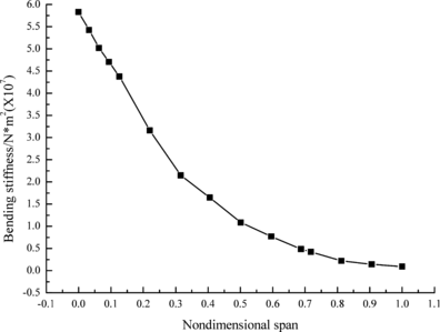
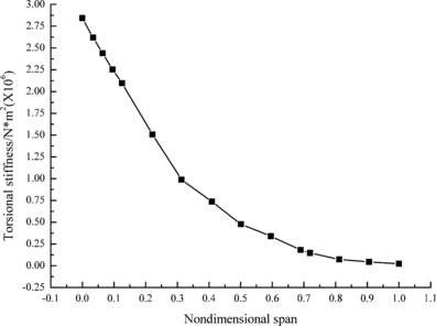
Figures 2 and 3 show the bending and torsional stiffness of different cross sections, respectively. It can be seen that both of them decrease along wingspan. It is noteworthy that torsional stiffness value is significantly less than that of bending stiffness at the same nondimensional span.
|
| Figure 2. Bending stiffness of different cross sections |
|
| Figure 3. Torsional stiffness of different cross sections |
3. A rapid aeroelasticity optimization method
The stiffness of large aspect ratio wing is relatively weak, which will brings a serious impact on aeroelasticity characteristics. At the same time, the increment of stiffness will lead to an unwieldy structure design. So, an integrated aeroelasticity optimization method, considering strength, stiffness, stability, static aeroelasticity characteristics and weight of the wing structure, is particularly important. Among these factors, static aeroelastictity characteristics analysis is an iterative process, which spent large time and just can give a range for the divergent velocity based on the traditional time domain method. Large time expense takes new challenges to the aeroelasticity optimization method, which leads to many optimization design of high aspect ratio wing can not be successfully carried out. In this part, divergent velocity analysis is carried out firstly. Then, its influence factors are discussed. Finally, a rapid aeroelasticity optimization method, controlling these influence factors replace the traditional iterative process, is introduced.
3.1 Divergent velocity analysis
Both structural deformation and aerodynamic distribution are influenced by static aeroelasticity characteristics. The effect is small when flight speed is slow. And it increased with the increased of flight speed until a critical speed is reached. And then, a divergence phenomenon is occurred. This critical speed is divergent velocity. Take example for a two-dimensional wing [21], bending and torsional deformation of the wing are simulated as sink-float and pitch of the airfoil. Aerodynamic load caused by sink-float is feeble, so just pitch is considered in airfoil aeroelasticity problem. Practical airfoil attack angle is composed of initial attack angle and torsion angle under the function of aerodynamic pressure. Moment of aerodynamic pressure on stiffness center can be written as
|
|
(10) |
where is dynamic pressure, is airfoil area, is cross section chord, is moment coefficient, is slope of lift curve, while is the distance between stiffness center and aerodynamic center.
Constraints of the airfoil are applied by two springs. Equilibrium equation of aerodynamic moment and spring elastic moment is written as
|
|
(11) |
where is spring elastic coefficient. Torsion angle can be obtained and written as
|
|
(12) |
When the denominator in Equation (12) equals to zero, torsion angle drives to infinite. By now, the wing is in a divergent state. And divergent velocity can be written as
|
|
(13) |
It also can be rewritten as
|
|
(14) |
It can be seen from Equation (14) that divergent velocity is composed of two parts data. The left part is related to wing configuration and flight condition, while the right one is wing structural parameters. In the whole aeroelasticity optimization process, it is only the right part varying. Divergent velocity increases with the increase of torsional stiffness, while decreases with the increase of distance between stiffness center and aerodynamic center. It is proportional to the divergent velocity and . So, divergent velocity can be adjusted by changing the torsional stiffness and the distance between stiffness center and aerodynamic center in the aeroelasticity optimization process.
3.2 Optimization design method
For general multidisciplinary optimization problem, it can be described by optimum objective function , constraint condition
or
and design variable
| , . |
(1) Objective function
The main object of aeroelasticity optimization design is to reduce the weight and improve aeroelasticity characteristics. Lift/drag ratio is selected as the index of aeroelasticity characteristics. The optimum objective function can be written as
|
|
(15) |
where is the weight after optimization, is the maximum weight in design variable span, is lift/drag ratio under the function of static aeroelasticity and is weight coefficient. In the present study, and . The negative coefficient in is to make both objective functions have the same trend. The weight coefficient values can be adjusted according actual optimization problems.
(2) Constraint conditions
The constraint conditions in aeroelasticity optimization contain strength, stiffness, stability, continuity and divergent velocity. The following will give detailed presentations about these constraint conditions.
a. Strength
The composite wing structure, which is shown in figure 1, is optimized in the present study. Strain value usually as the reference of strength evaluation in composite structures. The maximum tension, compression and shear strain of the composite wing structure are analyzed under the function of aeroelasticity. These parameters, comparison with the constraint values, reflect whether the wing structure meets strength requirement. The constraint conditions of strength can be seen in Equation (16). Where is the maximum tensile strain, is the maximum compression strain while is the maximum shear strain.
|
|
(16) |
b. Stiffness
Stiffness constraint condition is mainly reflected in bending and torsional deformation. The maximum bending and torsion deformation are usually happened in the wing tip. So, it is just need to extract the results of wing tip and compared them with constraint values. The constraint conditions of stiffness can be seen in Equation (17). Where is the maximum torsion angle, while is the maximum elastic axis flexivity.
|
|
(17) |
c. Stability
The main part of wing structure is a stiffened plate structure. It is likely to have an axial compression buckling. Critical load of the stiffened plate structure can be expressed as
|
|
(18) |
Where , is shape factor, and are equivalent shear modulus and area of web of the stringer, while is bending stiffness of the stiffened plate structure.The constrait conditions of stability is that the critical load is larger than working condition.
d. Continuity
A bad wing structure form is easy to be designed when every design variable as independent parameter. So, continuity between adjacent skins or skin and its stringer need to be considered in aeroelasticity optimization design. Continuity between adjacent skins mainly affects manufacture. It is set 0.8-1.2 here. Continuity between skin and its stringer is achieved through the area ratio. In the present study, stringer area is set two-thirds of skin area, which can be adjusted in the range of ±10%.
e. Divergent velocity
It is just a divergent velocity range can be obtained in the traditional time-domain aeroelasticity analysis. At the same time, it spends a lot of time. The time-domain aeroelasticity analysis method is nearly impossible to be used in aeroelasticity optimization design. Divergent velocity increases with the increase of torsional stiffness, while decreases with the increase of distance between stiffness center and aerodynamic center. It is proportional to the divergent velocity and . So, the constraint about divergent velocity can be equivalent to the control of . In the present study, divergent velocity of the optimized wing structure is set not less than 95% of the initial value.
(3) Design variables
The stress condition of wing different regions is different in the flight state. So, different region has its own thickness value will take advantage. Wing finite element model is divided into many regions and each region has its own property. Thickness is the most concerned design variable in current study.
(4) Optimization process
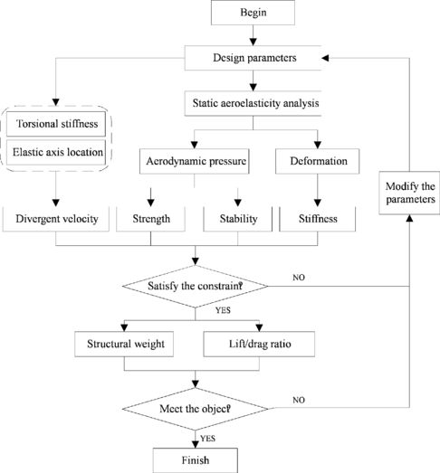
Whole optimization process is carried out in the software of iSIGHT. Multi-Island genetic algorithm is used to wing optimization design. Elastic axis location and torsional stiffness characteristics of the initial model design are analyzed firstly, which as the first constraint condition. Then, aeroelasiticity analysis of the wing structure is carried out and other constraint conditions are obtained. It can be seen from the results that whether all the parameters can meet constraint conditions. If it did, wing weight and lift/drag ratio are output, if not, design variables need to be modified and computed again. Static strength and stability are analyzed through FEM software of NASTRAN while elastic axis location and torsional stiffness in the FORTRAN code based on above introduction. Figure 4 shows the whole optimization process.
|
| Figure 4. Aeroelasticity optimization process |
3.3 Results and discussion
Table 1 shows the optimization results of the objects. The whole optimization design costs about 15 hours. Ordinarily, static aeroelasticity analysis for one individual costs more than ten hours based on the traditional time-domain method, which can not be accepted in the optimization design. The optimization method of the present study is very efficient. It can be seen that wing weight decreases 17.9% while lift/drag ratio increases 5.88%. Both optimization objects have ideal results. At the same time, the value of just decreases to 97.34% of the initial one, which has a well control on divergent velocity. The method can be well used in aeroelasticity optimization of wing structure.
| Object | Trend | Initial value | Optimized result | Changed rate |
| Weight | Decline | 346Kg | 284Kg | 17.9% |
| Lift/drag ratio | Increase | 10.2 | 10.8 | 5.88% |
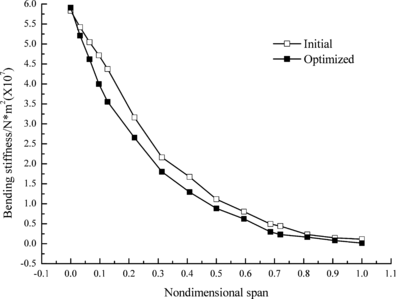
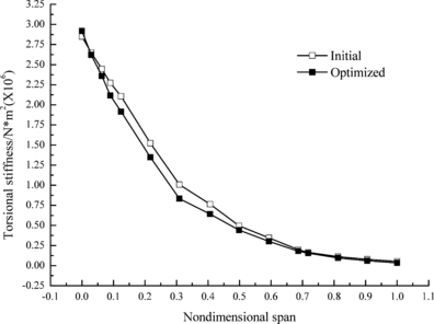
Figures 5 and 6 show the change of bending and torsional stiffness of different cross sections in initial and optimized wing structure, respectively. It can be seen that both stiffness values decrease obviously and the decrement of torsional stiffness is slightly less than that of bending stiffness. It is because that torsional stiffness directly affect lift coefficient and is constrained by the divergent velocity.
|
| Figure 5. Change of bending stiffness |
|
| Figure 6. Change of torsional stiffness |
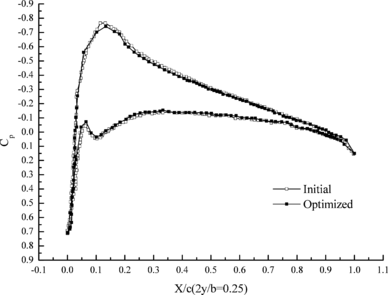
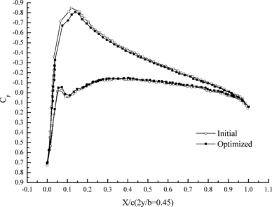
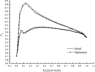
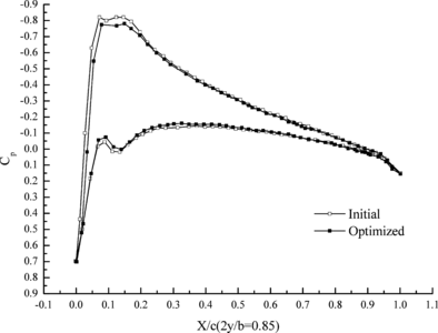
Figure 7 shows the change of aerodynamic distribution of different cross sections. It can be seen that the pressure differences between top and down aerofoil section decrease after optimization. Flexibility of wing structure is increased through aeroelasticity optimization design, which leads to the decrement of lift coefficient under the effect of aeroelasticity.
|
|
| (a) 25% cross section | (b) 45% cross section |
|
|
| (c) 65% cross section | (d) 85% cross section |
| Figure 7. Change of aerodynamic distribution | |
4. Conclusions
A rapid aeroelasticity optimization method based on the stiffness characteristics was proposed in the present study. Some useful conclusion can be drawn as follows:
(1) Both torsional stiffness and the distance between stiffness center and aerodynamic center have a direct impact on the divergent velocity. The divergent velocity can be adjusted by changing the correlative structural parameters.
(2) A rapid aeroelasticity optimization method based on the stiffness characteristics is introduced. Large time expense in static aeroelasticity analysis based on the traditional time-domain method is solved. After optimization, both structural and aerodynamic characteristics have a large improvement while satisfying the constraint conditions.
(3) Both bending and torsional stiffness decrease obviously after the optimization, while the pressure differences between top and down aerofoil section have the same trend.
Acknowledgements
This study is supported by the National Nature Science Foundation of China (No. 51305351).
References
[1] Wakayama. Blended-wing-body optimization problem setup, AIAA Paper 2000-4740, 2000.
[2] Guruswamy G.P., Obayashi S. Study on the use of high-fidelity methods in aeroelastic optimization. Journal of Aircraft, 41(3):616-619, 2004.
[3] Yang Q., Liang Q., Yang Y.N. Static aeroelastic optimization with CFD method. Acta Aerodynamica Sinica, 23(1):16-20, 2005.
[4] Zhang K.S., Han Z.H., Li W.J., Song W.P. Coupled aerodynamic/structural optimization of a subsonic transport wing using a surrogate model. Journal of Aircraft, 45(6):2167-2170, 2008.
[5] Alonso J.J., LeGresley P., Pereyra V. Aircraft design optimization. Math. Comput. Simul., 79(6):1948-1958, 2009.
[6] Venter G., Sobieszczanski-Sobieski J. Multidisciplinary optimization of a transport aircraft wing using particle swarm optimization. Structural and Multidisciplinary Optimization, 26(11):121-131, 2004.
[7] Jeon K.S., Lee J.W., Byun Y.H. Multidisciplinary design approach using repetitive response surface enhancement and global optimization. Proceedings of the 2008 Ninth ACIS International Conference on Software Engineering, Artificial Intelligence, Networking and Parallel/Distributed, 25-28, 2008.
[8] Mastroddi F., Tozzi M., Capanolo V. On the use of geometry design variables in the MDO analysis of wing structures with aeroelastic constraints on stability and response. Aerospace Science and Technology, 15:196-206, 2011.
[9] Hua Su, Liangxian Gu, Chunlin Gong. Static aeroelastic optimization of hypersonic aircraft based on high-fidelity model. Journal of Aerospace Power, 28(8):1836-1842, 2013.
[10] Nikbay M., Kuru M.N. Reliability based multidisciplinary optimization of aeroelastic systems with structural and aerodynamic uncertainties. Journal of Aircraft, 50(3):708-715, 2013.
[11] Sleesongsom S., Bureerat S. New conceptual design of aeroelastic wing structures by multi-objective optimization. Engineering Optimization, 45(1):107-122, 2013.
[12] Li W.W., Pak C. Aeroelastic optimization study based on the X-56A model. AIAA Paper, AIAA-2014-2052, 2014.
[13] Ting E., Lebofsky S., Nguyen N., Trinh K. Static aeroelastic scaling and analysis of a sub-scale flexible wing wind tunnel model. AIAA Paper, AIAA-2014-0838, 2014.
[14] Stanford B.K., Dunning P.D. Optimal topology of aircraft rib and spar structures under aeroelastic loads. AIAA Paper, AIAA-2014-0633, 2014.
[15] Mallik W., Kapania R.K., Schetz J.A. Aeroelastic analysis and optimization of flexible wing aircraft with a novel control effector. AIAA SciTech, Kissimmee, Florida, 56th AIAA Structures, Structural Dynamics, and Materials Conference, 5-9 January 2015.
[16] Stanford B., Jutte C. Trim and structural optimization of subsonic transport wings using nonconventional aeroelastic tailoring. AIAA Aviation Conference, Atlanta, GA, June 16-20, 2014.
[17]Francois G., Cooper J.E., Weaver P.M. Aeroelastic tailoring using rib/spar orientations: experimental investigation. AIAA SciTech, Kissimmee, Florida, 56th AIAA Structures, Structural Dynamics, and Materials Conference, 5-9 January 2015.
[18] Roscher B., Madsen H.A., Griffith D.T. Combined structural optimization and aeroelastic analysis of a vertical axis wind turbine. AIAA SciTech, Kissimmee, Florida, 33rd Wind Energy Symposium, 5-9 January 2015.
[19] Zuo Y.T., Gao Z.H., Chen G., Wang X.P., Li Y.M. Efficient aero-structural design optimization: coupling based on reverse iteration of structural model. Science China, 58:307-315, 2015.
[20] Huo S.H., Wang F.S., Yuan Z., Yue Z.F. Mesh regeneration method for jig-shape optimization design of the high-aspect-ratio wing. Advances in Mechanical Engineering, 513637:1-8, 2013.
[21] Zhao Y., Hu H. Structural modeling and aeroelastic analysis of high-aspect-ratio composite wing. Chinese journal of Aeronautics, 18(1):25-30, 2005.
Document information
Published on 08/02/19
Accepted on 09/12/18
Submitted on 04/04/18
Volume 35, Issue 1, 2019
DOI: 10.23967/j.rimni.2018.12.002
Licence: CC BY-NC-SA license