| Line 340: | Line 340: | ||
{| style="text-align: center; border: 1px solid #BBB; margin: 1em auto; width: auto;max-width: auto;" | {| style="text-align: center; border: 1px solid #BBB; margin: 1em auto; width: auto;max-width: auto;" | ||
|- | |- | ||
| − | |style="padding:10px;"| [[Image: | + | |style="padding:10px;"| [[Image:Campbell_2019a_7850_test-image19.png|510px]] |
|- style="text-align: center; font-size: 75%;" | |- style="text-align: center; font-size: 75%;" | ||
| colspan="1" style="padding:10px;"| '''Figure 17'''. Comparison of capacity curves for reinforced masonry walls without and with openings (models) | | colspan="1" style="padding:10px;"| '''Figure 17'''. Comparison of capacity curves for reinforced masonry walls without and with openings (models) | ||
| Line 348: | Line 348: | ||
{| style="text-align: center; border: 1px solid #BBB; margin: 1em auto; width: auto;max-width: auto;" | {| style="text-align: center; border: 1px solid #BBB; margin: 1em auto; width: auto;max-width: auto;" | ||
|- | |- | ||
| − | |style="padding:10px;"| [[Image: | + | |style="padding:10px;"| [[Image:Campbell_2019a_5456_test-image20.png|510px]] |
|- style="text-align: center; font-size: 75%;" | |- style="text-align: center; font-size: 75%;" | ||
| colspan="1" style="padding:10px;"| '''Figure 18'''. Comparison of capacity curves for reinforced masonry walls without and with openings (models) | | colspan="1" style="padding:10px;"| '''Figure 18'''. Comparison of capacity curves for reinforced masonry walls without and with openings (models) | ||
Revision as of 15:53, 29 January 2020
Abstract
In this work a numerical model to obtain the capacity curves of clay masonry walls with openings is presented. These curves represent the non-linear structural behavior of masonry walls with openings subjected to loads in their own plane. The openings represent non-structural elements like doors or windows, among others. These walls can be considered as reinforced or confined masonry and the opening must be rectangular and may have different dimensions and a variable position inside the wall.
The main result of the model was a capacity curve, which is compared with the curves obtained from laboratory tests (for walls with and without openings). The model was developed using the software ANSYS version 14.5, based on the model proposed by Campbell and Durán.
Keywords: Masonry walls, non-linear model, capacity curves, pushover analysis
1. Introduction
Masonry is a construction material widely used across the world, mainly in structures a few stories high, due to its advantages over other construction materials in terms of cost, thermal and acoustic behavior, and its rapidity in construction, among others. However, a clear disadvantage of this material is its structural behavior facing seismic loads, due to its low tensile strength, the low homogeneity of this material and the high influence of workmanship in its construction. Due to the disadvantages, in Chile this material is mainly used for the construction of social housing of up to four storeys [1,2].
The last seismic events occurred in Chile (Central Chile, 1985; Antofagasta, 1995; Maule, 2010; Iquique, 2014; Coquimbo, 2015) has shown an acceptable performance of masonry structures only with a few situations of large damage. This behaviour has been probably achieved due to the strict requirements of the Chilean seismic analysis and design codes.
As a consequence of the aforementioned and adding that not all countries have to consider seismic forces in their structural design, there is scarce studies and testing of masonry walls with horizontal loads and even less in walls having openings have been published. Some relevant studies on this field are those developed by [3,4,5,6,7,8].
Another problem regularly encountered is that when it comes to walls with openings it is no longer so simple to generate a macro model, because its structural behavior is clearly different from that of a full wall. In particular, the only reference the Chilean standards NCh1928 [9] and NCh2123 [10] make with respect to walls with openings, deals with the special assembly that must be taken into account in the perimeter of the openings and the size of them. Other codes –as the National Building Code of Canada [11] or the New Zealand Standard [12]– suggest special studies or experimentation.
Currently, the resources for the investigation of the behavior of this type of material have been scarce in spite of the great need that exists due to its common use. This is why it is necessary to study a numerical model that can predict the behaviour that this type of material would present in construction, being able to vary dimensions, openings and reinforcements used, modifying them according to the object of study that is presented and that can deliver values close to reality.
For these reasons, the main objective of this work was the improvement of a numerical model that can reflect the behavior of the type of wall just exposed, covering different types of openings that are commonly used.
2. Proposed model
This work introduces a description of the model to represent the non-linear behavior of masonry walls developed by Campbell and Durán [13]. This work adds the option for the wall to have a rectangular opening (window or door). Firstly, the structure of the model is explained in general, considering the elements used of the ANSYS program [14] and input data for the definition of the wall. Subsequently, the numerical solution used is described in general terms and finally the graphic results obtained from the model are described as well. The model developed here did not describe all the aspects in detail, since these were fully shown in the work of Balboa and Silva [15].
2.1 Description of the model
As described in Campbell and Durán's contribution, the non-linear behavior of masonry walls is greatly explained by the bond between bricks and mortar [13]. For this reason, the most relevant part of the model is the representation of the mortar and the union between this and the masonry units through special elements.
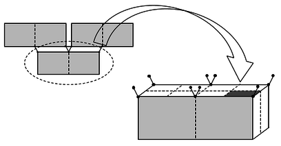
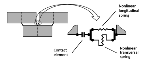
In general, this simplified micro-model considers finite elements for masonry units, and a model for joints defined by two parallel non-linear springs (one longitudinal and one transversal to the joint) that define the axial and transverse behavior of the mortar. In addition, a contact element, which joins these springs in series, defines the behavior of the interface between the mortar and the unit, considering the friction and the adherence limit between these two elements. This set is connected to the nodes of each finite element, as shown in Figure 1.
|
| Figure 1. Model of the joint between bricks and mortar [13] |
In the model, different types of masonry walls can be generated: simple, reinforced and confined, and, as indicated at the beginning of this section, this work adds the option of generating a rectangular opening. This opening may have different dimensions and position within the masonry wall, as long as the top of the masonry is adjacent to the bond beam. In addition, the model gives the possibility of using different types of discretization for the units, that is, each unit can be subdivided in smaller elements as it generates more connection elements between the adjacent elements.
In order to generate the model, elements existing within the ANSYS program were used, which are "solid finite element", "non-linear spring element" and "contact element", each associated and defined by a material (linear or non-linear), failure criteria or stress-strain relation and input parameters of the mechanical behavior. In this way, each structural component is defined in the model, such as the masonry unit (brick or block), mortar, steel and concrete.
The model units are organized considering a link type operation. This type of link is used to have a more accurate response of the model and to better reproduce the kinematic and tensional behavior of the units and the joints.
2.1.1 Elements type considered
Solid elements for units and reinforced concrete
The model considers the SOLID65 element of ANSYS to represent the units of masonry and the reinforced concrete (in the case of confined masonry). This solid finite element considers the possibility of including reinforcing bars, which can be defined in three different directions to represent them and, in that case, the steel of the reinforced concrete is considered as distributed throughout the element. This element is a hexahedron with 8 nodes at its vertexes and 3 degrees of freedom at each node (displacement in the X, Y and Z directions).
The non-linear behavior of these types of elements is also a combination of the non-linear behavior of the main material and the reinforcing material. If the element is used to represent reinforced concrete, then the main material is concrete while the reinforcing material is steel.
To represent the non-linear behavior of the concrete or the units, the model has the ability to predict and modify the stress-strain relation by incorporating "cracks" (tensile) and "crushing" (compression). This means that the model introduces a weakness plane in the normal direction of the face of the crack or assumes the weakening of the crushing material. The model also considers a reduction factor to represent the decrease in shear strength at the face of the crack. The presence of cracking or crushing within an element is verified at the connecting points. All these possible failures are controlled through a set of parameters and coefficients specially defined for the material.
For the implementation of the model, a simplified stress-strain curve was considered for the units and the concrete, which depend on the quality of both materials and can be modified. The tensile behavior was considered as linear elastic up to a stress equal to 1/10 of the maximum compression and taking into account the same initial modulus of elasticity considered for compression. After this point, the behavior becomes perfectly plastic.
Non-linear spring elements
For the mortar model and reinforcing bars in masonry (in the case of reinforced masonry), a non-linear spring element was used. For this reason, the COMBIN39 element of ANSYS was chosen. This type of element is a unidirectional spring with a generalized multi-linear force-displacement law. This element was defined as a bar with two nodes and has up to three degrees of freedom for each node (X, Y and Z direction).
The structural behavior of the element is defined by a multi-linear force-displacement curve. The points in the curve represent the internal force on the element and the relative displacement between the nodes. It should be noted that the curve has some simple restrictions: it must be completely defined in the first and third quadrant (of the force-displacement plane) in addition to having its origin point in coordinate (0,0), any vertical segment should be avoided and the last segment must have a positive slope.
Mortar joints springs (longitudinal y transverse)
The mechanical properties and thickness of the mortar were used for the definition of the non-linear springs to represent the longitudinal and transverse structural behavior of the mortar.
In this case, the force-displacement curve of these elements was defined taking into account the stress-strain curve of the mortar, the tributary area of the unit over the node and the thickness of the joint. The force at each point of the force-displacement curve was defined by considering the stress multiplied by the tributary area (Figure 2), and the displacement was defined by taking into account the unit deformation multiplied by the length of the spring. This length was taken as 9/10 of the thickness of the joint, considering that the length of the contact element is 1/10 of the thickness of the joint. This idea was valid for longitudinal and transverse springs.
| Figure 2. Tributary area in the junctions for non-linear springs [13] |
The tensile behavior of the mortar was considered linear elastic up to a tension equal to 1/10 of the maximum compression, taking into account the same initial modulus of elasticity considered in compression. After this point, the behavior becomes perfectly plastic. If the tensile stress between the unit and the mortar is less than this limit (1/10 of compressive strength), the upper limit of the tensile section is modified to the tensile strength between the unit and the mortar.
Due to the lack of information on the shear stress-strain behavior of mortar, the stress-strain curve for shear deformation was similarly defined and proportional to the curve for compression. The maximum shear strength was considered equal to 1/10 of the maximum compressive force. After this point, the behavior becomes perfectly plastic. If the bond strength between the brick and the mortar is less than this limit (1/10 compressive strength), the upper limit is modified up to the bond strength between the unit and the mortar.
Springs for reinforcing bars in masonry (vertical and horizontal)
In the definition of non-linear springs to represent vertical and horizontal reinforcing bars, the mechanical and geometric (diameter) properties of steel were used.
In this case, the force-displacement curve of these elements was defined by taking into account the stress-strain curve of the steel and the cross-sectional area of each bar. The force of each point of the force-displacement curve was defined by considering the stress multiplied by the cross-sectional area and the displacement was defined by considering the unit deformation multiplied by the length of the bar.
For the particular case of non-linear springs representing the vertical reinforcing bars, they were defined as an element that runs from the bottom of the wall to the top. This is justified because in Chile it is very common that, when building masonry, mortar is not used to fill in the holes of the brick where the bars go. Obviously, both Chilean and international masonry standards state that holes must be filled.
Contact elements
For the interface model between the units and the mortar, the node-to-node contact elements were used, which in this case corresponds to the ANSYS CONTA178 element. This element represents the contact and slip between the two nodes.
The element was defined by two nodes, an initial separation between them and the initial status of the contact. Each node had up to three degrees of freedom (X, Y and Z direction). The interface was assumed perpendicular to the line I-J.
The element CONTA178 had an infinite resistance in compression and the user defines its stiffness in compression (normal to the contact surface). For reasons of stability and convergence, the tensile stiffness can be regulated as a percentage of the stiffness in compression (as a weak spring). This element is able to withstand friction in a tangential direction to the contact surface.
2.2 Input parameters
To define the proposed model, a file with input data must be prepared to be used in ANSYS. The parameters to be included in this file are related to masonry type (simple, reinforced or confined), material quality (modulus of elasticity, Poisson coefficient, maximum strength), type of analysis control (force or displacement), geometry of the wall (length, height), geometry of the individual elements (dimensions of the unit, thickness of the joints, sections of the confinement elements, dimensions of the reinforcements), dimensions and location of the opening, etc.
For the definition of the materials considered in this model it is also necessary to define the stress-strain curves of the units, concrete and steel. These parameters must be stated in the definition of the respective elements that use them.
2.3 Numerical solution
The numerical solution of the model was carried out in two stages: the application of the vertical load (own weight plus overload) and the horizontal load, since these two loading processes require two different numerical solutions.
For vertical loads an automatic time-stepping was used, where the software internally defines the time step to consider the iterative solution. Conversely, for horizontal loads a predefined time stepping was used, where the user defines the time step. For both cases, the solution was obtained through the Newton-Raphson method to solve non-linear equations.
2.4 Output graph results
The most important result of the analysis was the "capacity curve" of the modeled wall. This curve represents the structural behavior of the wall under horizontal loads applied at the top of the wall. The curve shows the horizontal force applied at the base of the wall against the horizontal displacement in its upper part.
Through the input file there is also the possibility of controlling the graphs to obtain as the result of the analysis of internal stress, internal forces, general displacements, internal deformations, status of the contact elements, etc.
3. Walls tested in the laboratory
This section presents the masonry walls tested in the laboratory that will be used as a reference to develop a comparison with the proposed model. From these tests the information needed to implement the numerical model of the wall is obtained, such as the geometric, structural and reinforcing properties used in the different elements that compose it.
One of the wall with openings tests used was performed within the frame of an undergraduate thesis at Universidad de La Serena [16]. The other four tests of confined masonry walls with different type openings were carried out at Universidad de Chile [17,18].
Additionally, a comparison was made with the results of a reinforced masonry wall tested at Universidad de La Serena [19] and a confined masonry wall of the series developed by Ogaz [17] at Universidad de Chile. These last two walls have no openings.
3.1 Masonry walls with openings
This section presents the walls with openings tested in the laboratory, corresponding to one of reinforced masonry made at Universidad de La Serena and ten of confined masonry (two of each type of opening) performed at Universidad de Chile.
3.1.1 Test of reinforced masonry wall with opening
This test was carried out considering the use of a reaction frame with a double acting dynamic actuator that allows the wall to be subjected to a horizontal cyclic load, which through defined frequencies and displacements measured at the top of the wall results in a hysteresis cycles (of force and displacements for every displacement amplitude). Considering the maximum values of force and displacement of every cycle, the capacity curve of the test can be defined. This capacity curve can subsequently be compared with the proposed model. The test was controlled by displacement, which is the most common way of controlling this type of test, since it avoids the probable sudden failure and collapse of the wall, with the safety implications that it has. The test was performed by carrying out a uniform increase after a given number of cycles of 0,2 mm and with a sinusoidal dynamic function of 0,5 Hz frequency that was maintained throughout the test.
The wall had the following technical specifications:
- Brick MqHv cm, arranged in running bond with a total of 22 rows and horizontal and vertical joints of 2 cm ( kN/m; kN/m).
- Reinforced bond beam, foundation and vertical reinforcement with A630-420H steel ( kN/m; kN/m).
- Horizontal reinforcement diameter of 4,2 mm of AT560-500H quality ( kN/m; kN/m).
- Maximum compressive strength of the mortar kN/m with kN/m.
- Maximum compressive strength of the concrete kN/m with kN/m.
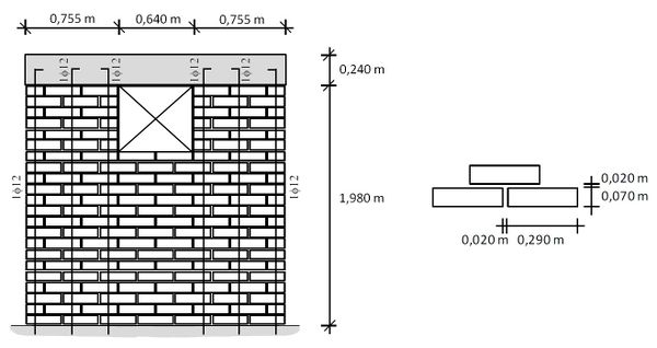
- The size of the opening is 0,64 m wide and 0,54 m high.
The geometry information is shown in Figure 3.
| Figure 3. Geometric characteristics and layout of reinforcements (RM Wall with opening) |
3.1.2 Tests of confined masonry walls with openings
At Universidad de Chile, four different types of walls with openings were constructed (testing two walls for each type), achieving a total of eight tests related to confined masonry walls with openings, maintaining the same general dimensions and properties characteristics to compare their subsequent behavior. All of these types of walls were compared to the proposed model. These tests were executed through the use of a reaction frame equipped with a hydraulic double action cylinder. The walls were subjected to alternating cycles of lateral loading, applied in the plane of the wall, stopping the test when a maximum displacement of 28 mm was reached. All the tests were controlled by the lateral displacement of the wall, measuring in the middle of the wall at half the height of the bond beam, applying two load cycles for each level of displacement. In the case of walls with non-symmetrical openings(MLC-T4 and MLC-T6), the tests and models were defined considering the two directions of the horizontal load and response (positive and negative cycles).
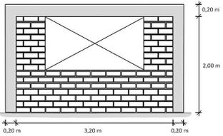
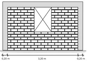
The tested walls had different shape, size and location of the opening. They were classified as indicated in Table 1. The geometry for each wall is presented in Figures 4 and 5.
| Type of wall | Denomination | Identification of wall | Size of the opening |
| Wall with large centered window | Type 2 | MLC-T2-01; MLC-T2-02 | b=2,005 m; h=1,125 m |
| Wall with small centered window | Type 3 | MLC-T3-01; MLC-T3-02 | b=0,785 m; h=1,125 m |
| Wall with door – centered window | Type 4 | MLC-T4-01; MLC-T4-02 | b=1,090 m; h=1,000 m |
| Wall with centered door | Type 6 | MLC-T6-01; MLC-T6-02 | b=0,480 m; h=2,000 m |
| Figure 4. Geometric characteristics of walls with large (left, MLC-T2) and small (right, MLC-T3) window | |
| Figure 5. Geometric characteristics of walls with door and window (left, MLC-T4) and centered door (right, MLC-T6) | |
For all the walls tested the properties of the materials used were:
- Ceramic brick MqP, grade 1 cm, arranged in running bond with a total of 16 rows and horizontal and vertical joints of 12 mm ( kN/m; kN/m).
- Reinforcement steel used A630-420H ( kN/m; kN/m).
- Maximum compressive strength of the mortar kN/m with kN/m.
- Maximum compressive strength of the concrete kN/m with kN/m.
- Column width 0,20 m with longitudinal reinforcement 410 and stirrups 6 @ 15.
- Beam height 0,20 m with longitudinal reinforcement 410 and stirrups 6 @ 15.
- The size of the openings is presented on Table 1.
3.2 Tests of masonry walls without openings
This section shows a full wall with reinforced masonry tested at Universidad de La Serena [19] and a full wall with confined masonry tested at Universidad de Chile [17]. The materials and geometry characteristics, as well as those used for the tests, were the same of the previous tests shown for Universidad de La Serena and Universidad de Chile. The geometric characteristics of the walls are shown in Figures 6 and 7. The walls tested at University of La Serena were three of the same characteristics (Walls 01, 02 and 03). The walls tested at University of Chile were two of the same characteristics (MLC-T1-01 and MLC-T1-02).
| Figure 6. Geometric characteristics and layout of the wall reinforcement of the reinforced masonry (Walls 01, 02 and 03) |
| Figure 7. Geometric characteristics of confined masonry wall (MLC-T1-01 and MLC-T1-02) |
4. Implementation of the model
4.1 Comparison between tests and models
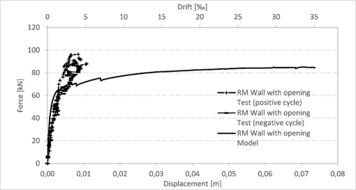
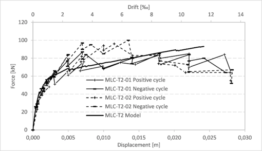
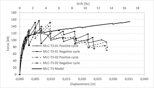
This section presents the comparison between the capacity curves obtained from the models and those obtained through the tests for each of the walls described in section 3.1.1 (Figure 8), section 3.1.2 (Figures 9 to 14) and section 3.2 (Figures 15 and 16). More details regarding these results can be found in the work of Balboa and Silva [15]. In all these graphs, the drift was calculated considering the horizontal displacement divided by 2,1 m, which is the height of the walls from the bottom to the center of the bond beam.
|
| Figure 8. Capacity curves of reinforced masonry wall (test and model) |
|
| Figure 9. Capacity curves for walls MLC-T2 (tests and model) |
|
| Figure 10. Capacity curves for walls MLC-T3 (tests and model) |
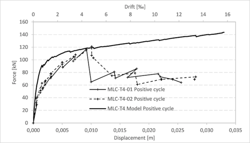
|
| Figure 11. Capacity curves for walls MLC-T4 (positive cycle tests and model) |
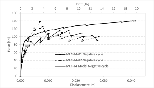
|
| Figure 12. Capacity curves for walls MLC-T4 (negative cycle tests and model) |
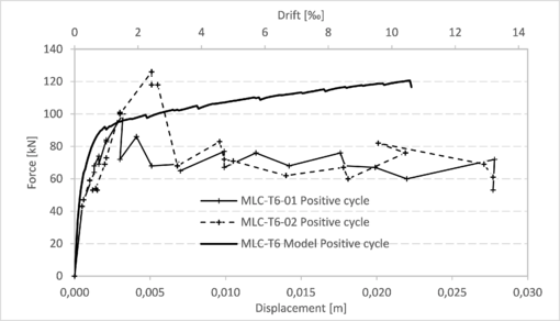
|
| Figure 13. Capacity curves for walls MLC-T6 (positive cycle tests and model) |
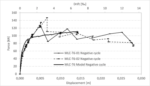
|
| Figure 14. Capacity curves for walls MLC-T6 (negative cycle tests and model) |
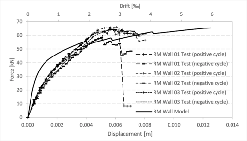
|
| Figure 15. Comparison of capacity curves for reinforced masonry walls 01, 02 and 03 (tests and model) |
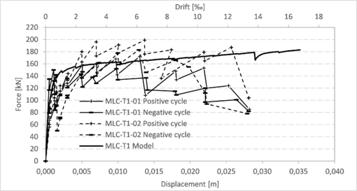
|
| Figure 16. Comparison of capacity curves for walls MLC-T1 (tests and model) |
4.2 Comparison of models with different openings
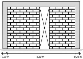
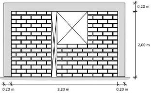
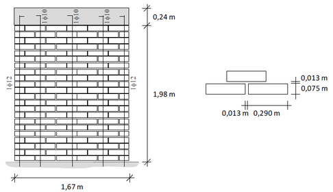
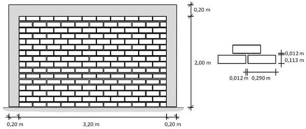
Additionally, in Figure 17 a full reinforced masonry wall (the same of Figure 6 of section 3.2) is compared with the behaviour, according to the proposed model, of a reinforced masonry wall with a door opening (at the center, b=0,56 m and h=1,98 m) and with a window opening (at the center, b=1,11 m and h=1,32 m). Finally, Figure 18 shows a comparison between a full confined masonry wall (the same of Figure 7 of section 3.2) and confined masonry walls with different openings (MLC-T2, MLC-T3 and MLC-T6 in positive cycle).
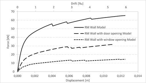
|
| Figure 17. Comparison of capacity curves for reinforced masonry walls without and with openings (models) |
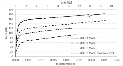
|
| Figure 18. Comparison of capacity curves for reinforced masonry walls without and with openings (models) |
5. Conclusions
In this work a numerical model to represent the structural behavior of masonry walls with openings and loaded in their own plane was implemented with software ANSYS. The quality of the model was verified by comparing its results with those obtained from laboratory tests carried out in Chile. The model delivers acceptable results and they are according to the quality of the materials and the different dimensions of the walls and their openings.
In most cases, it can be seen that the parameter of the models that comes closer to those obtained from the tests is that of maximum force and to a lesser extent the maximum displacement. A likely explanation for this is that virtually all of the input parameters that were entered into the models were based on the resistance of the structural elements, since these are generally the most tested and studied elements. On the other hand, parameters related to displacement, such as the modulus of elasticity, are generally obtained from literature and may have different values for the same material.
It is important to highlight that most of the model curves closely resemble the curves of the tests, mainly in the initial stretches (on average up to the value of 1 cm of displacement and/or about 0,5 ‰ of drift). After this, the model curves always ascend until reaching the point of maximum force, unlike the test curves, that after achieving the maximum force point, they descend until reaching the wall failure.
Although it is a good model, it could be greatly improved if parameters were determined through tests instead of estimated and defined according to values provided by literature, such as tensile strength and adherence between brick and mortar, coefficient of friction, mortar shear strength, modulus of elasticity of the mortar.
References
[1] Santa María H., Hube M.A., Rivera F., Yepes-Estrada C., Valcárcel J.A. Development of national and local exposure models of residential structures in Chile. Natural Hazards, 86:55–79, 2017.
[2] Astroza M., Moroni O., Brzev S., Tanner J. Seismic performance of engineered masonry buildings in the 2010 Maule Earthquake. Earthquake Spectra, 28(1):385–406, 2012.
[3] López J., Oller Martínez S., Oñate E. Cálculo del comportamiento de la mampostería meediante elementos finitos. Monografía CIMNE M46, Barcelona, España, 1998.
[4] Lourenço P.B. Computational strategies for masonry structures. PhD Thesis, Delft University Press, Delft, The Netherlands, 1996.
[5] Abdulla K., Cunningham L., Gillie M. Simulating masonry wall behaviour using a simplified micro-model approach. Engineering Structures, 151:349, 2017.
[6] Noh N.M., Liberatore L., Mollaioli F., Tesfamariam S. Modelling of masonry infilled RC frames subjected to cyclic loads: State of the art review and modelling with OpenSees. Engineering Structures, 150:599–621, 2017.
[7] Anic F., Penava D., Abrahamczyk L., Sarhosis V. Computational evaluation of experimental methodologies of out-of-plane behavior of framed-walls with openings. Earthquakes and Structures, 16(3):265-277, 2019.
[8] Sarhosis V., Lemos J.V. A detailed micro-modelling approach for the structural analysis of masonry assemblages. Computers and Structures, 206:66-81, 2018.
[9] Instituto Nacional de Normalización (I.N.N.). Norma Chilena Oficial NCh1928.Of1993 Mod. 2003 Albañilería armada-Requisitos para diseño y cálculo, Santiago, Chile, 2003.
[10] Instituto Nacional de Normalización (I.N.N.). Norma Chilena Oficial NCh2123.Of1997 Albañilería confinada-Requisitos de diseño y cálculo, Santiago, Chile, 1997.
[11] Canada G of CNRC. National Building Code of Canada 2015 - National Research Council Canada, Canada, 2016.
[12] New Zealand Standard. NZS 4230:2004 Design of Reinforced Concrete Masonry Structures. New Zealand, 2004.
[13] Campbell J., Durán M. Numerical model for nonlinear analysis of masonry walls. Revista de la Construcción 16(2):189–201, 2017.
[14] ANSYS. Swanson Analysis Systems, Inc. ANSYS v. 14. Pennsylvania, USA, 2013.
[15] Balboa R., Silva V. Modelo numérico para el análisis no-lineal de muros de albañilería con aberturas. Memoria para Optar al Título de Ingeniero Civil, Departamento de Ingeniería en Obras Civiles, Universidad de La Serena, Chile, 2015.
[16] Cortés J., Esquivel J. Estudio teórico-experimental de un muro de albañilería armada con abertura solicitado a carga cíclica horizontal. Memoria para Optar al Título de Ingeniero Civil, Departamento de Ingeniería en Obras Civiles, Universidad de La Serena, Chile, 2014.
[17] Ogaz O. Estudio experimental de muros de albañilería con aberturas y cuantía reducida de refuerzo sujetos a carga lateral alternada. Memoria para Optar al Título de Ingeniero Civil, Departamento de Ingeniería Civil, Universidad de Chile, Chile, 2004.
[18] Yáñez F., Astroza M., Holmberg A., Ogaz O. Behavior of confined masonry shear walls with large openings. 13th World Conference on Earthquake Engineering, Vancouver, Canada, 2004.
[19] Díaz L., Arancibia I., Vicencio M., Durán M., Campbell J. Ensayos de muros de albañilería armada de esbelteces mayores a uno solicitados a carga cíclica. IX Jornadas Chilenas de Sismología e Ingeniería Antisísmica, Concepción, Chile, 2005.
Document information
Published on 22/01/20
Accepted on 08/12/19
Submitted on 01/07/19
Volume 36, Issue 1, 2020
DOI: 10.23967/j.rimni.2019.12.003
Licence: CC BY-NC-SA license
Share this document
Keywords
claim authorship
Are you one of the authors of this document?
