m (Move page script moved page Draft Samper 876641692 to Onate et al 2004h) |
|||
| (130 intermediate revisions by one other user not shown) | |||
| Line 1: | Line 1: | ||
| − | + | Published in ''Encyclopedia of Computational Mechanics'', Encyclopedia of Computational Mechanics, E. Stein, R. de Borst and T.J.R. Hughes (Eds.), John Wiley & Sons Ltd, Vol. 3, Chapter 18, pp. 579 - 607, 2004<br /> | |
| − | + | DOI: 10.1002/9781119176817 | |
| − | + | ||
| − | ''' | + | |
| − | + | ||
| − | + | ||
| − | + | ||
| − | + | ||
| − | + | ||
| − | + | ||
| − | + | ||
| − | + | ||
| − | + | ||
| − | + | ||
| − | + | ||
| − | + | ||
| − | + | ||
| − | + | ||
==Abstract== | ==Abstract== | ||
| Line 34: | Line 18: | ||
Wave resistance in practical cases amounts to <math display="inline">10</math> to <math display="inline">60%</math> of the total resistance of a ship in still water (Raven, 1996 <span id="citeF-84"></span>[[#cite-84|[84]]]). It increases very rapidly at high speeds dominating the viscous component for high speed ships. Furthermore, wave resistance is very sensitive to the hull form design and easily affected by small shape modifications. For all these reasons, the possibility to predict and reduce the wave resistance is an important target. | Wave resistance in practical cases amounts to <math display="inline">10</math> to <math display="inline">60%</math> of the total resistance of a ship in still water (Raven, 1996 <span id="citeF-84"></span>[[#cite-84|[84]]]). It increases very rapidly at high speeds dominating the viscous component for high speed ships. Furthermore, wave resistance is very sensitive to the hull form design and easily affected by small shape modifications. For all these reasons, the possibility to predict and reduce the wave resistance is an important target. | ||
| − | The prediction of the wave pattern and the wave resistance of a ship has challenged mathematicians and hydrodynamicists for over a century. The Boundary Element Method (BEM) is the basis of many computational algorithms developed in past years. Here the flow problem is solved using a simple potential model. BEM methods, termed by hydrodynamicists as Panel Methods may be classified into two categories. The first one uses the Kelvin wave source as the elementary singularity. The main advantage of such scheme is the automatic satisfaction of the radiation condition. The theoretical background of this method was reviewed by Wehausen (1970) <span id="citeF-103"></span>[[#cite-103|[103]]], while computational aspects can be found in Soding (1996) <span id="citeF-87"></span>[[#cite-87|[87]]] and Jenson and Soding (1989) <span id="citeF-58"></span>[[#cite-58|[58]]]. The second class of BEM schemes uses the Rankine source as the elementary singularity. This procedure, first presented by Dawson (1977) <span id="citeF-29"></span>[[#cite-29|[29]]], has been widely applied in practice and many improvements have been addressed to account for the nonlinear wave effects. Among these, a succesful example is the Rankine Panel Method (Xia, 1986 <span id="citeF-106"></span>[[#cite-106|[106]]]; Jenson and Soding, 1989 <span id="citeF-58"></span>[[#cite-58|[58]]]; Nakos and Sclavounos, 1990 <span id="citeF- | + | The prediction of the wave pattern and the wave resistance of a ship has challenged mathematicians and hydrodynamicists for over a century. The Boundary Element Method (BEM) is the basis of many computational algorithms developed in past years. Here the flow problem is solved using a simple potential model. BEM methods, termed by hydrodynamicists as Panel Methods may be classified into two categories. The first one uses the Kelvin wave source as the elementary singularity. The main advantage of such scheme is the automatic satisfaction of the radiation condition. The theoretical background of this method was reviewed by Wehausen (1970) <span id="citeF-103"></span>[[#cite-103|[103]]], while computational aspects can be found in Soding (1996) <span id="citeF-87"></span>[[#cite-87|[87]]] and Jenson and Soding (1989) <span id="citeF-58"></span>[[#cite-58|[58]]]. The second class of BEM schemes uses the Rankine source as the elementary singularity. This procedure, first presented by Dawson (1977) <span id="citeF-29"></span>[[#cite-29|[29]]], has been widely applied in practice and many improvements have been addressed to account for the nonlinear wave effects. Among these, a succesful example is the Rankine Panel Method (Xia, 1986 <span id="citeF-106"></span>[[#cite-106|[106]]]; Jenson and Soding, 1989 <span id="citeF-58"></span>[[#cite-58|[58]]]; Nakos and Sclavounos, 1990 <span id="citeF-109"></span>[[#cite-109|[109]]]). |
In addition to the important developments in potential flow panel methods for practical ship hydrodynamics analysis during the period 1960-1980, much research in the second half of the twentieth century was oriented towards the introduction of viscosity in the CFD analysis. In the 1960's the viscous flow research was mainly focused in 2D boundary layer theory and by the end of the decade several methods for arbitrary pressure gradients were available. This research continued to solve the 3D case during the following decade and an evaluation of the capability of the new methods to predict ship wave resistance was carried out at different workshops (Bai and McCarthy, 1979 <span id="citeF-7"></span>[[#cite-7|[7]]]; Larsson, 1981 <span id="citeF-61"></span>[[#cite-61|[61]]]; Noblesse and McCarthy, 1983 <span id="citeF-69"></span>[[#cite-69|[69]]]). Here application to some well specified test cases were reported and numerical and experimental results compared acceptable well for most part of the boundary layer along the hull, while wrong results were obtained near the stern. This prompted additional research and by the end of the 1980's a number of numerical procedures for solving the full viscous flow equation accounting for simple turbulence modes based on Reynolds averaged Navier-Stokes (RANS) equations were available. Considerable improvements for predicting the stern flow were reported in subsequent workshops organized in the 1990's (Kim and Lucas, 1990 <span id="citeF-59"></span>[[#cite-59|[59]]]; Reed ''et al.'' , 1990<span id="citeF-85"></span>[[#cite-85|[85]]]; Beck ''et al.'', 1993 <span id="citeF-8"></span>[[#cite-8|[8]]]; Raven, 1996 <span id="citeF-84"></span>[[#cite-84|[84]]]; Soding, 1996 <span id="citeF-87"></span>[[#cite-87|[87]]]; Janson and Larsson, 1996 <span id="citeF-57"></span>[[#cite-57|[57]]]; Alessandrini and Delhommeau, 1996 <span id="citeF-1"></span>[[#cite-1|[1]]]; Miyata, 1996 <span id="citeF-67"></span>[[#cite-67|[67]]], Löhner ''et al.'', 1998 <span id="citeF-64"></span>[[#cite-64|[64]]]). A good review of the status of CFD in ship hydrodynamics in the last part of the 20th century can be found in Larsson ''et al.'' (1998) <span id="citeF-62"></span>[[#cite-62|[62]]]. | In addition to the important developments in potential flow panel methods for practical ship hydrodynamics analysis during the period 1960-1980, much research in the second half of the twentieth century was oriented towards the introduction of viscosity in the CFD analysis. In the 1960's the viscous flow research was mainly focused in 2D boundary layer theory and by the end of the decade several methods for arbitrary pressure gradients were available. This research continued to solve the 3D case during the following decade and an evaluation of the capability of the new methods to predict ship wave resistance was carried out at different workshops (Bai and McCarthy, 1979 <span id="citeF-7"></span>[[#cite-7|[7]]]; Larsson, 1981 <span id="citeF-61"></span>[[#cite-61|[61]]]; Noblesse and McCarthy, 1983 <span id="citeF-69"></span>[[#cite-69|[69]]]). Here application to some well specified test cases were reported and numerical and experimental results compared acceptable well for most part of the boundary layer along the hull, while wrong results were obtained near the stern. This prompted additional research and by the end of the 1980's a number of numerical procedures for solving the full viscous flow equation accounting for simple turbulence modes based on Reynolds averaged Navier-Stokes (RANS) equations were available. Considerable improvements for predicting the stern flow were reported in subsequent workshops organized in the 1990's (Kim and Lucas, 1990 <span id="citeF-59"></span>[[#cite-59|[59]]]; Reed ''et al.'' , 1990<span id="citeF-85"></span>[[#cite-85|[85]]]; Beck ''et al.'', 1993 <span id="citeF-8"></span>[[#cite-8|[8]]]; Raven, 1996 <span id="citeF-84"></span>[[#cite-84|[84]]]; Soding, 1996 <span id="citeF-87"></span>[[#cite-87|[87]]]; Janson and Larsson, 1996 <span id="citeF-57"></span>[[#cite-57|[57]]]; Alessandrini and Delhommeau, 1996 <span id="citeF-1"></span>[[#cite-1|[1]]]; Miyata, 1996 <span id="citeF-67"></span>[[#cite-67|[67]]], Löhner ''et al.'', 1998 <span id="citeF-64"></span>[[#cite-64|[64]]]). A good review of the status of CFD in ship hydrodynamics in the last part of the 20th century can be found in Larsson ''et al.'' (1998) <span id="citeF-62"></span>[[#cite-62|[62]]]. | ||
| Line 232: | Line 216: | ||
The solution of above problems in the context of the finite element method (FEM) has been attempted in a number of ways. The underdiffusive character of the Galerkin FEM for high convection flows (which incidentaly also occurs for centred FD and FV methods) has been corrected by adding some kind of artificial viscosity terms to the standard Galerkin equations. A good review of such approach can be found in Zienkiewicz and Taylor, Vol. 3 2000 <span id="citeF-107"></span>[[#cite-107|[107]]] and Donea and Huerta, 2003 <span id="citeF-31"></span>[[#cite-31|[31]]]. | The solution of above problems in the context of the finite element method (FEM) has been attempted in a number of ways. The underdiffusive character of the Galerkin FEM for high convection flows (which incidentaly also occurs for centred FD and FV methods) has been corrected by adding some kind of artificial viscosity terms to the standard Galerkin equations. A good review of such approach can be found in Zienkiewicz and Taylor, Vol. 3 2000 <span id="citeF-107"></span>[[#cite-107|[107]]] and Donea and Huerta, 2003 <span id="citeF-31"></span>[[#cite-31|[31]]]. | ||
| − | A popular way to overcome the problems with the incompressibility constraint is by introducing a pseudo-compressibility in the flow and using implicit and explicit algorithms developed for this kind of problems, such as artificial compressibility schemes (Chorin, 1967A <span id="citeF-14"></span>[[#cite-14|[14]]] popular way to overcome the problems with the incompressibility constraint is by introducing a pseudo-compressibility in the flow and using implicit and explicit algorithms developed for this kind of problems, such as artificial compressibility schemes (Chorin, 1967 <span id="citeF-14"></span>[[#cite-14|[14]]]; Farmer ''et al.'', 1993 <span id="citeF-35"></span>[[#cite-35|[35]]]; Peraire ''et al.'', 1994 <span id="citeF-82"></span>[[#cite-82|[82]]]; Briley ''et al.'', 1995 <span id="citeF-10"></span>[[#cite-10|[10]]]; Sheng ''et al.'', 1996 <span id="citeF-86"></span>[[#cite-86|[86]]]) and preconditioning techniques (Idelsohn ''et al.'', 1995 <span id="citeF-51"></span>[[#cite-51|[51]]]). Other FEM schemes with good stabilization properties for the convective and incompressibility terms are based in Petrov-Galerkin (PG) techniques. The background of PG methods are the non-centred (upwind) schemes for computing the first derivatives of the convective operator in FD and FV methods. More recently a general class of Galerkin FEM has been developed where the standard Galerkin variational form is extended with adequate residual-based terms in order to achieve a stabilized numerical scheme (Codina, 1998 <span id="citeF-16"></span>[[#cite-16|[16]]], 2000 <span id="citeF-17"></span>[[#cite-17|[17]]]). Among the many FEM of this kind we can name the Streamline Upwind Petrov Galerkin (SUPG) method (Hughes and Brooks, 1979 <span id="citeF-45"></span>[[#cite-45|[45]]]; Brooks and Hughes, 1982 <span id="citeF-11"></span>[[#cite-11|[11]]]; Tezduyar and Hughes, 1983 <span id="citeF-97"></span>[[#cite-97|[97]]]; Hughes and Tezduyar, 1984 <span id="citeF-46"></span>[[#cite-46|[46]]]; Hughes and Mallet, 1986 <span id="citeF-48"></span>[[#cite-48|[48]]]; Idelsohn ''et al.'', 1995 <span id="citeF-51"></span>[[#cite-51|[51]]]; Storti ''et al.'', 1995 <span id="citeF-88"></span>[[#cite-88|[88]]], 1997 <span id="citeF-89"></span>[[#cite-89|[89]]]; Cruchaga and Oñate, 1997 <span id="citeF-27"></span>[[#cite-27|[27]]], 1999 <span id="citeF-28"></span>[[#cite-28|[28]]]), the Galerkin Least Square (GLS) method (Hughes ''et al.'', 1989 <span id="citeF-50"></span>[[#cite-50|[50]]]; Tezduyar, 1991 <span id="citeF-94"></span>[[#cite-94|[94]]]; Tezduyar ''et al.'', 1992a <span id="citeF-99"></span>[[#cite-99|[99]]]), the Taylor-Galerkin method (Donea, 1984 <span id="citeF-30"></span>[[#cite-30|[30]]]), the Characteristic Galerkin method (Douglas and Russell, 1982 <span id="citeF-32"></span>[[#cite-32|[32]]]; Pironneau, 1982 <span id="citeF-83"></span>[[#cite-83|[83]]]; Löhner ''et al.'', 1984 <span id="citeF-63"></span>[[#cite-63|[63]]]) and its variant the characteristic Based Split (CBS) method (Zienkiewicz and Codina, 1995 <span id="citeF-108"></span>[[#cite-108|[108]]]; Codina ''et al.'', 1998 <span id="citeF-23"></span>[[#cite-23|[23]]]; Codina and Zienkiewicz, 2002 <span id="citeF-25"></span>[[#cite-25|[25]]]), pressure gradient operator methods (Codina and Blasco, 1997 <span id="citeF-22"></span>[[#cite-22|[22]]], 2000 <span id="citeF-24"></span>[[#cite-24|[24]]]) and the Subgrid Scale (SGS) method (Hughes, 1995 <span id="citeF-44"></span>[[#cite-44|[44]]]; Brezzi ''et al.'', 1997 <span id="citeF-9"></span>[[#cite-9|[9]]]; Codina, 2000 <span id="citeF-17"></span>[[#cite-17|[17]]], 2002 <span id="citeF-21"></span>[[#cite-21|[21]]]). | + | A popular way to overcome the problems with the incompressibility constraint is by introducing a pseudo-compressibility in the flow and using implicit and explicit algorithms developed for this kind of problems, such as artificial compressibility schemes (Chorin, 1967A <span id="citeF-14"></span>[[#cite-14|[14]]]) popular way to overcome the problems with the incompressibility constraint is by introducing a pseudo-compressibility in the flow and using implicit and explicit algorithms developed for this kind of problems, such as artificial compressibility schemes (Chorin, 1967 <span id="citeF-14"></span>[[#cite-14|[14]]]; Farmer ''et al.'', 1993 <span id="citeF-35"></span>[[#cite-35|[35]]]; Peraire ''et al.'', 1994 <span id="citeF-82"></span>[[#cite-82|[82]]]; Briley ''et al.'', 1995 <span id="citeF-10"></span>[[#cite-10|[10]]]; Sheng ''et al.'', 1996 <span id="citeF-86"></span>[[#cite-86|[86]]]) and preconditioning techniques (Idelsohn ''et al.'', 1995 <span id="citeF-51"></span>[[#cite-51|[51]]]). Other FEM schemes with good stabilization properties for the convective and incompressibility terms are based in Petrov-Galerkin (PG) techniques. The background of PG methods are the non-centred (upwind) schemes for computing the first derivatives of the convective operator in FD and FV methods. More recently a general class of Galerkin FEM has been developed where the standard Galerkin variational form is extended with adequate residual-based terms in order to achieve a stabilized numerical scheme (Codina, 1998 <span id="citeF-16"></span>[[#cite-16|[16]]], 2000 <span id="citeF-17"></span>[[#cite-17|[17]]]). Among the many FEM of this kind we can name the Streamline Upwind Petrov Galerkin (SUPG) method (Hughes and Brooks, 1979 <span id="citeF-45"></span>[[#cite-45|[45]]]; Brooks and Hughes, 1982 <span id="citeF-11"></span>[[#cite-11|[11]]]; Tezduyar and Hughes, 1983 <span id="citeF-97"></span>[[#cite-97|[97]]]; Hughes and Tezduyar, 1984 <span id="citeF-46"></span>[[#cite-46|[46]]]; Hughes and Mallet, 1986 <span id="citeF-48"></span>[[#cite-48|[48]]]; Idelsohn ''et al.'', 1995 <span id="citeF-51"></span>[[#cite-51|[51]]]; Storti ''et al.'', 1995 <span id="citeF-88"></span>[[#cite-88|[88]]], 1997 <span id="citeF-89"></span>[[#cite-89|[89]]]; Cruchaga and Oñate, 1997 <span id="citeF-27"></span>[[#cite-27|[27]]], 1999 <span id="citeF-28"></span>[[#cite-28|[28]]]), the Galerkin Least Square (GLS) method (Hughes ''et al.'', 1989 <span id="citeF-50"></span>[[#cite-50|[50]]]; Tezduyar, 1991 <span id="citeF-94"></span>[[#cite-94|[94]]]; Tezduyar ''et al.'', 1992a <span id="citeF-99"></span>[[#cite-99|[99]]]), the Taylor-Galerkin method (Donea, 1984 <span id="citeF-30"></span>[[#cite-30|[30]]]), the Characteristic Galerkin method (Douglas and Russell, 1982 <span id="citeF-32"></span>[[#cite-32|[32]]]; Pironneau, 1982 <span id="citeF-83"></span>[[#cite-83|[83]]]; Löhner ''et al.'', 1984 <span id="citeF-63"></span>[[#cite-63|[63]]]) and its variant the characteristic Based Split (CBS) method (Zienkiewicz and Codina, 1995 <span id="citeF-108"></span>[[#cite-108|[108]]]; Codina ''et al.'', 1998 <span id="citeF-23"></span>[[#cite-23|[23]]]; Codina and Zienkiewicz, 2002 <span id="citeF-25"></span>[[#cite-25|[25]]]), pressure gradient operator methods (Codina and Blasco, 1997 <span id="citeF-22"></span>[[#cite-22|[22]]], 2000 <span id="citeF-24"></span>[[#cite-24|[24]]]) and the Subgrid Scale (SGS) method (Hughes, 1995 <span id="citeF-44"></span>[[#cite-44|[44]]]; Brezzi ''et al.'', 1997 <span id="citeF-9"></span>[[#cite-9|[9]]]; Codina, 2000 <span id="citeF-17"></span>[[#cite-17|[17]]], 2002 <span id="citeF-21"></span>[[#cite-21|[21]]]). |
In this work a stabilized FEM for incompressible flows is derived taking as the starting point the modified governing equations of the flow problem formulated via a finite calculus (FIC) approach. The FIC method is based in invoking the balance of fluxes in a domain of finite size. This introduces naturally additional terms in the classical differential equations of infinitessimal fluid mechanics which are a function of the balance domain dimensions. The new terms in the modified governing equations provide naturally the necessary stabilization to the standard Galerkin finite element method. | In this work a stabilized FEM for incompressible flows is derived taking as the starting point the modified governing equations of the flow problem formulated via a finite calculus (FIC) approach. The FIC method is based in invoking the balance of fluxes in a domain of finite size. This introduces naturally additional terms in the classical differential equations of infinitessimal fluid mechanics which are a function of the balance domain dimensions. The new terms in the modified governing equations provide naturally the necessary stabilization to the standard Galerkin finite element method. | ||
| Line 296: | Line 280: | ||
|} | |} | ||
| − | We see that the FIC procedure introduces ''naturally'' an additional diffusion term into the standard convection-diffusion equation. This is the basis of the popular “artificial diffusion” method (Hirsch | + | We see that the FIC procedure introduces ''naturally'' an additional diffusion term into the standard convection-diffusion equation. This is the basis of the popular “artificial diffusion” method (Hirsch, 1990 <span id="citeF-42"></span>[[#cite-42|[42]]]). The characteristic length <math display="inline">h</math> is typically expressed as a function of the cell or element dimensions. The optimal or critical value of <math display="inline">h</math> can be computed from numerical stability conditions such as obtaining a physically meaningful solution, or even obtaining “exact” nodal values (Zienkiewicz and Taylor, 2000 <span id="citeF-107"></span>[[#cite-107|[107]]]; Oñate and Manzan, 1999 <span id="citeF-76"></span>[[#cite-76|[76]]], 2000 <span id="citeF-77"></span>[[#cite-77|[77]]]; Oñate, 2004 <span id="citeF-72"></span>[[#cite-72|[72]]]). |
Equation ([[#eq-13|13]]) can be extended to account for source and time effects. The full FIC equation for the transient convection-diffusion problem can be written in compact form as | Equation ([[#eq-13|13]]) can be extended to account for source and time effects. The full FIC equation for the transient convection-diffusion problem can be written in compact form as | ||
| Line 770: | Line 754: | ||
Note that the stabilization matrix <math display="inline">\hat{\boldsymbol K}</math> brings in an additional orthotropic diffusivity of value <math display="inline">\rho \displaystyle{h_k v_l\over 2}</math>. Matrices <math display="inline">{\boldsymbol A}, \hat {\boldsymbol K}</math> and <math display="inline">\hat{\boldsymbol C}</math> are dependent on the velocity field. The solution process can be advanced in time in a (quasi-nearly) implicit iterative manner using the following scheme. | Note that the stabilization matrix <math display="inline">\hat{\boldsymbol K}</math> brings in an additional orthotropic diffusivity of value <math display="inline">\rho \displaystyle{h_k v_l\over 2}</math>. Matrices <math display="inline">{\boldsymbol A}, \hat {\boldsymbol K}</math> and <math display="inline">\hat{\boldsymbol C}</math> are dependent on the velocity field. The solution process can be advanced in time in a (quasi-nearly) implicit iterative manner using the following scheme. | ||
| + | <span id="step-1"></span> | ||
''Step 1'' | ''Step 1'' | ||
| − | + | <span id="eq-44"></span> | |
{| class="formulaSCP" style="width: 100%; text-align: left;" | {| class="formulaSCP" style="width: 100%; text-align: left;" | ||
|- | |- | ||
| Line 778: | Line 763: | ||
|- | |- | ||
| style="text-align: center;" | <math>\bar{\boldsymbol u}^{n+1,i} = \bar{\boldsymbol u}^n - \Delta t {\boldsymbol M}^{-1} [({\boldsymbol A}^{n+\theta _1,i-1}+ {\boldsymbol K} + \hat {\boldsymbol K}^{n+\theta _1,i-1})\bar{\boldsymbol u}^{n+\theta _1,i-1}-{\boldsymbol G}{\boldsymbol p}^{n+\theta _2,i-1} + {\boldsymbol C} \bar {\boldsymbol c}^{n+\theta _3,i-1}-{\boldsymbol f}^{n+1}] </math> | | style="text-align: center;" | <math>\bar{\boldsymbol u}^{n+1,i} = \bar{\boldsymbol u}^n - \Delta t {\boldsymbol M}^{-1} [({\boldsymbol A}^{n+\theta _1,i-1}+ {\boldsymbol K} + \hat {\boldsymbol K}^{n+\theta _1,i-1})\bar{\boldsymbol u}^{n+\theta _1,i-1}-{\boldsymbol G}{\boldsymbol p}^{n+\theta _2,i-1} + {\boldsymbol C} \bar {\boldsymbol c}^{n+\theta _3,i-1}-{\boldsymbol f}^{n+1}] </math> | ||
| + | |- | ||
|} | |} | ||
| style="width: 5px;text-align: right;white-space: nowrap;" | (44) | | style="width: 5px;text-align: right;white-space: nowrap;" | (44) | ||
|} | |} | ||
| − | + | <span id="step-2"></span> | |
| − | + | ''Step 2'' | |
| − | + | <span id="eq-45"></span> | |
{| class="formulaSCP" style="width: 100%; text-align: left;" | {| class="formulaSCP" style="width: 100%; text-align: left;" | ||
|- | |- | ||
| Line 793: | Line 779: | ||
| style="width: 5px;text-align: right;white-space: nowrap;" | (45) | | style="width: 5px;text-align: right;white-space: nowrap;" | (45) | ||
|} | |} | ||
| − | + | <span id="step-3"></span> | |
| − | + | ''Step 3'' | |
| − | + | <span id="eq-46"></span> | |
{| class="formulaSCP" style="width: 100%; text-align: left;" | {| class="formulaSCP" style="width: 100%; text-align: left;" | ||
|- | |- | ||
| Line 805: | Line 791: | ||
| style="width: 5px;text-align: right;white-space: nowrap;" | (46) | | style="width: 5px;text-align: right;white-space: nowrap;" | (46) | ||
|} | |} | ||
| − | + | <span id="step-4"></span> | |
| − | + | ''Step 4'' | |
| − | + | <span id="eq-47"></span> | |
{| class="formulaSCP" style="width: 100%; text-align: left;" | {| class="formulaSCP" style="width: 100%; text-align: left;" | ||
|- | |- | ||
| Line 820: | Line 806: | ||
In above <math display="inline">\theta _i</math> are time integration parameters with <math display="inline">0\le \theta _i\le 1</math> and <math display="inline">\bar{(\cdot )}^{n,i}</math> denotes nodal values at the <math display="inline">n</math>th time step and the ith iteration. <math display="inline">{\boldsymbol A}^{n+\theta _1,i-1}\equiv {\boldsymbol A}(\bar {\boldsymbol u}^{n+\theta _1,i-1})</math> etc. Also <math display="inline">(\cdot )^{n+\theta _i,0}\equiv (\cdot )^n</math> for the computations in step 1 at the onset of the iterations. | In above <math display="inline">\theta _i</math> are time integration parameters with <math display="inline">0\le \theta _i\le 1</math> and <math display="inline">\bar{(\cdot )}^{n,i}</math> denotes nodal values at the <math display="inline">n</math>th time step and the ith iteration. <math display="inline">{\boldsymbol A}^{n+\theta _1,i-1}\equiv {\boldsymbol A}(\bar {\boldsymbol u}^{n+\theta _1,i-1})</math> etc. Also <math display="inline">(\cdot )^{n+\theta _i,0}\equiv (\cdot )^n</math> for the computations in step 1 at the onset of the iterations. | ||
| − | Steps 1, 3 and 4 can be solved explicitely by choosing a ''lumped (diagonal) form'' of matrices | + | Steps [[#step-1|1]], [[#step-3|3]] and [[#step-4|4]] can be solved explicitely by choosing a ''lumped (diagonal) form'' of matrices <math display="inline">M</math> and <math display="inline">\hat {\boldsymbol M}</math>. In this manner the main computational cost is the solution of step [[#step-2|2]] involving the inverse of a Laplacian matrix. This can be solved very effectively using an iterative method. |
For <math display="inline">\theta _i\not =0</math> the iterative proces is unavoidable. The iterations follow until convergence is reached. This can be measured using an adequate error norm in terms of the velocity and pressure variables, or the residuals. Indeed some ot the <math display="inline">\theta _i</math>'s can be made equal to zero. Note that for <math display="inline">\theta _2=0</math> the algorithm is inconditionable unstable. A simple form is obtained making <math display="inline">\theta _1 = \theta _3=\theta _4=0</math>. This elliminates the non linear dependence with the velocity of matrices <math display="inline">{\boldsymbol A}</math> and <math display="inline">\hat{\boldsymbol K}</math> during the iterative scheme. | For <math display="inline">\theta _i\not =0</math> the iterative proces is unavoidable. The iterations follow until convergence is reached. This can be measured using an adequate error norm in terms of the velocity and pressure variables, or the residuals. Indeed some ot the <math display="inline">\theta _i</math>'s can be made equal to zero. Note that for <math display="inline">\theta _2=0</math> the algorithm is inconditionable unstable. A simple form is obtained making <math display="inline">\theta _1 = \theta _3=\theta _4=0</math>. This elliminates the non linear dependence with the velocity of matrices <math display="inline">{\boldsymbol A}</math> and <math display="inline">\hat{\boldsymbol K}</math> during the iterative scheme. | ||
Convergence of above solution scheme is however difficult for some problems. An enhanced version of the algorithm can be obtained by adding the term <math display="inline">\hat {\boldsymbol L} (\bar {\boldsymbol p}^{n+1,i} - \bar {\boldsymbol p}^{n+1,i-1})</math> where <math display="inline">\hat L_{ij} =\Delta t \int _{\Omega ^e} {\boldsymbol \nabla }^T N_i {\boldsymbol \nabla } N_j d\Omega </math> to the equation for the computation of the pressure in the second step. The new term acts as a preconditioner of the pressure equation given now by | Convergence of above solution scheme is however difficult for some problems. An enhanced version of the algorithm can be obtained by adding the term <math display="inline">\hat {\boldsymbol L} (\bar {\boldsymbol p}^{n+1,i} - \bar {\boldsymbol p}^{n+1,i-1})</math> where <math display="inline">\hat L_{ij} =\Delta t \int _{\Omega ^e} {\boldsymbol \nabla }^T N_i {\boldsymbol \nabla } N_j d\Omega </math> to the equation for the computation of the pressure in the second step. The new term acts as a preconditioner of the pressure equation given now by | ||
| − | + | <span id="eq-48"></span> | |
{| class="formulaSCP" style="width: 100%; text-align: left;" | {| class="formulaSCP" style="width: 100%; text-align: left;" | ||
|- | |- | ||
| Line 842: | Line 828: | ||
===6.2 Fractional step method=== | ===6.2 Fractional step method=== | ||
| − | The pressure can be split from the discretized momentum equations (see Eq.(44)) as | + | The pressure can be split from the discretized momentum equations (see Eq.([[#eq-44|44]])) as |
| − | + | <span id="eq-49"></span> | |
{| class="formulaSCP" style="width: 100%; text-align: left;" | {| class="formulaSCP" style="width: 100%; text-align: left;" | ||
|- | |- | ||
| Line 853: | Line 839: | ||
| style="width: 5px;text-align: right;white-space: nowrap;" | (49) | | style="width: 5px;text-align: right;white-space: nowrap;" | (49) | ||
|} | |} | ||
| − | + | <span id="eq-50"></span> | |
{| class="formulaSCP" style="width: 100%; text-align: left;" | {| class="formulaSCP" style="width: 100%; text-align: left;" | ||
|- | |- | ||
| Line 864: | Line 850: | ||
|} | |} | ||
| − | In above equations <math display="inline">\alpha </math> is a variable taking values equal to zero or one. For <math display="inline">\alpha =0</math>, <math display="inline">\delta p \equiv p^{n+1}</math> (first order scheme) and for <math display="inline">\alpha =1</math>, <math display="inline">\delta p =\Delta p</math> (second order scheme) (Codina, 2001). Note that in both cases the sum of Eqs.(49) and (50) gives the time discretization of the momentum equations with the pressures computed at <math display="inline">t^{n+1}</math>. The value of <math display="inline">\bar {\boldsymbol u}^{n+1}</math> from Eq.(50) is substituted now into (41b) to give | + | In above equations <math display="inline">\alpha </math> is a variable taking values equal to zero or one. For <math display="inline">\alpha =0</math>, <math display="inline">\delta p \equiv p^{n+1}</math> (first order scheme) and for <math display="inline">\alpha =1</math>, <math display="inline">\delta p =\Delta p</math> (second order scheme) (Codina, 2001 <span id="citeF-19"></span>[[#cite-19|[19]]]). Note that in both cases the sum of Eqs.([[#eq-49|49]]) and ([[#eq-50|50]]) gives the time discretization of the momentum equations with the pressures computed at <math display="inline">t^{n+1}</math>. The value of <math display="inline">\bar {\boldsymbol u}^{n+1}</math> from Eq.([[#eq-50|50]]) is substituted now into ([[#eq-41b|41b]]) to give |
| − | + | <span id="eq-51a"></span> | |
{| class="formulaSCP" style="width: 100%; text-align: left;" | {| class="formulaSCP" style="width: 100%; text-align: left;" | ||
|- | |- | ||
| Line 877: | Line 863: | ||
The product <math display="inline">{\boldsymbol G}^T {\boldsymbol M}^{-1}{\boldsymbol G}</math> can be approximated by a laplacian matrix, i.e. | The product <math display="inline">{\boldsymbol G}^T {\boldsymbol M}^{-1}{\boldsymbol G}</math> can be approximated by a laplacian matrix, i.e. | ||
| − | + | <span id="eq-51b"></span> | |
{| class="formulaSCP" style="width: 100%; text-align: left;" | {| class="formulaSCP" style="width: 100%; text-align: left;" | ||
|- | |- | ||
| Line 890: | Line 876: | ||
A semi-implicit algorithm can be derived as follows.<br/> | A semi-implicit algorithm can be derived as follows.<br/> | ||
| − | + | <span id="s1"></span> | |
| + | ''Step 1'' Compute the nodal fractional velocities <math display="inline">{\boldsymbol u}^*</math> explicitely from Eq.([[#eq-49|49]]) with <math display="inline">{\boldsymbol M}={\boldsymbol M}_d</math> where subscript <math display="inline">d</math> denotes a diagonal matrix. | ||
<br/> | <br/> | ||
| − | + | <span id="s2"></span> | |
| − | + | ''Step 2'' Compute <math display="inline">\delta \bar {\boldsymbol p}</math> from Eq.([[#eq-51a|51a]]) (using Eq.([[#eq-51b|51b]])) as | |
| − | + | <span id="eq-52"></span> | |
{| class="formulaSCP" style="width: 100%; text-align: left;" | {| class="formulaSCP" style="width: 100%; text-align: left;" | ||
|- | |- | ||
| Line 905: | Line 892: | ||
| style="width: 5px;text-align: right;white-space: nowrap;" | (52) | | style="width: 5px;text-align: right;white-space: nowrap;" | (52) | ||
|} | |} | ||
| − | + | <span id="s3"></span> | |
| − | + | ''Step 3'' Compute the nodal velocities <math display="inline"> \bar{\boldsymbol u}^{n+1}</math> explicitely from Eq.([[#eq-50|50]]) with <math display="inline">{\boldsymbol M}={\boldsymbol M}_d</math> | |
<br/> | <br/> | ||
| + | <span id="s4"></span> | ||
| + | ''Step 4'' Compute <math display="inline"> \bar{\boldsymbol c}^{n+1}</math> explicitely from Eq.([[#eq-46|46]]) using <math display="inline">{\boldsymbol M}_d</math>. | ||
| − | + | <span id="s5"></span> | |
| − | + | ''Step 5'' Compute <math display="inline"> \bar{\boldsymbol \pi }^{n+1}</math> explicitely from Eq.([[#eq-47|47]]) with <math display="inline">\hat {\boldsymbol M} = \bar{\boldsymbol M}_d</math>. | |
| − | + | ||
| − | This algorithm has an additional step than the iterative algorithm of Section 6.1. The advantage is that now Steps 1 and 2 can be fully linearized by choosing <math display="inline">\theta _1 = \theta _3=\theta _4=0</math>. Also the equation for the pressure variables in Step 2 has improved stabilization properties due to the additional laplacian matrix <math display="inline">\hat{\boldsymbol L}</math>. | + | This algorithm has an additional step than the iterative algorithm of Section [[#6.1 Discretization of the fluid flow equations|6.1.]] The advantage is that now Steps [[#s1|1]] and [[#s2|2]] can be fully linearized by choosing <math display="inline">\theta _1 = \theta _3=\theta _4=0</math>. Also the equation for the pressure variables in Step [[#s2|2]] has improved stabilization properties due to the additional laplacian matrix <math display="inline">\hat{\boldsymbol L}</math>. |
| − | Details on the stability properties of the FIC formulation for incompressible fluid flow problems can be found in Oñate ''et al.'' (2002). | + | Details on the stability properties of the FIC formulation for incompressible fluid flow problems can be found in Oñate ''et al.'' (2002) <span id="citeF-79"></span>[[#cite-79|[79]]]. |
===6.3 Discretization of free-surface wave equation=== | ===6.3 Discretization of free-surface wave equation=== | ||
| − | The solution in time of Eq.(39) can be written in terms of the nodal velocities computed from the flow solution, as | + | The solution in time of Eq.([[#eq-39|39]]) can be written in terms of the nodal velocities computed from the flow solution, as |
| − | + | <span id="eq-53"></span> | |
{| class="formulaSCP" style="width: 100%; text-align: left;" | {| class="formulaSCP" style="width: 100%; text-align: left;" | ||
|- | |- | ||
| Line 932: | Line 920: | ||
|} | |} | ||
| − | Eq.(53) can now be discretized in space using the standard Galerkin method and solved ''explicitely'' for the nodal wave heights at <math display="inline">t^{n+1}</math>. Typically the general algorithm will be as follows: | + | Eq.([[#eq-53|53]]) can now be discretized in space using the standard Galerkin method and solved ''explicitely'' for the nodal wave heights at <math display="inline">t^{n+1}</math>. Typically the general algorithm will be as follows: |
<ol> | <ol> | ||
| − | <li>Solve for the nodal velocities <math display="inline">\bar{\boldsymbol u}^{n+1}</math> and the pressures <math display="inline">\bar{\boldsymbol p}^{n+1}</math> in the fluid domain using any of the algorithms of Sections 6.1 and 6.2. When solving for the pressure equation impose <math display="inline">p^{n+1}= p_a</math> at the free-surface <math display="inline">\Gamma _\beta </math>. </li> | + | <li>Solve for the nodal velocities <math display="inline">\bar{\boldsymbol u}^{n+1}</math> and the pressures <math display="inline">\bar{\boldsymbol p}^{n+1}</math> in the fluid domain using any of the algorithms of Sections [[#6.1 Discretization of the fluid flow equations|6.1]] and [[#6.2 Fractional step method|6.2.]] When solving for the pressure equation impose <math display="inline">p^{n+1}= p_a</math> at the free-surface <math display="inline">\Gamma _\beta </math>. </li> |
| − | <li>Solve for the free-surface elevation <math display="inline">\beta ^{n+1}</math> (viz. Eq.(53)). </li> | + | <li>Solve for the free-surface elevation <math display="inline">\beta ^{n+1}</math> (viz. Eq.([[#eq-53|53]])). </li> |
<li>Compute the new position of the mesh nodes in the fluid domain at time <math display="inline">t^{n+1}</math>. Alternatively, regenerate a new mesh. </li> | <li>Compute the new position of the mesh nodes in the fluid domain at time <math display="inline">t^{n+1}</math>. Alternatively, regenerate a new mesh. </li> | ||
| Line 945: | Line 933: | ||
The mesh updating process can also include the free-surface nodes, although this is not strictly necessary. An ''hydrostatic adjustement'' can be implemented once the new free-surface elevation is computed simply by imposing the pressure at the nodes on the reference surface as | The mesh updating process can also include the free-surface nodes, although this is not strictly necessary. An ''hydrostatic adjustement'' can be implemented once the new free-surface elevation is computed simply by imposing the pressure at the nodes on the reference surface as | ||
| − | + | <span id="eq-54"></span> | |
{| class="formulaSCP" style="width: 100%; text-align: left;" | {| class="formulaSCP" style="width: 100%; text-align: left;" | ||
|- | |- | ||
| Line 958: | Line 946: | ||
where <math display="inline">g</math> is the gravity constant. | where <math display="inline">g</math> is the gravity constant. | ||
| − | Eq.(54) takes into account the changes in the free-surface without the need of updating the reference surface nodes. A higher accuracy in the flow solution can be obtained by updating these nodes after a number of time steps. | + | Eq.([[#eq-54|54]]) takes into account the changes in the free-surface without the need of updating the reference surface nodes. A higher accuracy in the flow solution can be obtained by updating these nodes after a number of time steps. |
==7 FLUID-SHIP INTERACTION== | ==7 FLUID-SHIP INTERACTION== | ||
| Line 965: | Line 953: | ||
In both cases the computation of the ship motion involves solving the dynamic equations of the ship structure written as | In both cases the computation of the ship motion involves solving the dynamic equations of the ship structure written as | ||
| − | + | <span id="eq-55"></span> | |
{| class="formulaSCP" style="width: 100%; text-align: left;" | {| class="formulaSCP" style="width: 100%; text-align: left;" | ||
|- | |- | ||
| Line 976: | Line 964: | ||
|} | |} | ||
| − | where <math display="inline">{\boldsymbol d}</math> and <math display="inline">\ddot {\boldsymbol d}</math> are the displacement and acceleration vectors of the nodes discretizing the ship structure, respectively, <math display="inline">{\boldsymbol M}_s</math> and <math display="inline">{\boldsymbol K}_s</math> are the mass and stiffness matrices of the structure and <math display="inline">{\boldsymbol f}_{ext}</math> is the vector of external nodal forces accounting for the fluid flow loads induced by the pressure and the viscous stresses. Clearly the main driving forces for the motion of the ship is the fluid pressure which acts in the form of a surface traction. Indeed Eq.(55) can be augmented with an appropriate damping term. The form of all the relevant matrices and vectors can be found in standard books on FEM for structural analysis (Zienkiewicz and Taylor, Vol 2 2000). | + | where <math display="inline">{\boldsymbol d}</math> and <math display="inline">\ddot {\boldsymbol d}</math> are the displacement and acceleration vectors of the nodes discretizing the ship structure, respectively, <math display="inline">{\boldsymbol M}_s</math> and <math display="inline">{\boldsymbol K}_s</math> are the mass and stiffness matrices of the structure and <math display="inline">{\boldsymbol f}_{ext}</math> is the vector of external nodal forces accounting for the fluid flow loads induced by the pressure and the viscous stresses. Clearly the main driving forces for the motion of the ship is the fluid pressure which acts in the form of a surface traction. Indeed Eq.([[#eq-55|55]]) can be augmented with an appropriate damping term. The form of all the relevant matrices and vectors can be found in standard books on FEM for structural analysis (Zienkiewicz and Taylor, Vol 2 2000 <span id="citeF-107"></span>[[#cite-107|[107]]]). |
| − | Solution of Eq.(55) in time can be performed using implicit or fully explicit time integration algorithms. In both cases the values of the nodal displacements, the velocities and the accelerations at time <math display="inline">t^{n+1}</math> are found. | + | Solution of Eq.([[#eq-55|55]]) in time can be performed using implicit or fully explicit time integration algorithms. In both cases the values of the nodal displacements, the velocities and the accelerations at time <math display="inline">t^{n+1}</math> are found. |
| − | A simple coupled fluid-ship-structure solution in time using, for instance, the fractional step method of Section 6.2 (for <math display="inline">\theta _1=\theta _2=\theta _3=\theta _4=0</math>) involves the following steps. | + | A simple coupled fluid-ship-structure solution in time using, for instance, the fractional step method of Section [[#6.2 Fractional step method|6.2]] (for <math display="inline">\theta _1=\theta _2=\theta _3=\theta _4=0</math>) involves the following steps. |
<br/> | <br/> | ||
| + | <span id="step1"></span> | ||
| + | '''Step 1''' Solve for the fractional velocities <math display="inline">\bar{\boldsymbol u}^*</math> using Eq.([[#eq-49|49]]). Here use of <math display="inline">\alpha =1</math> is recommended. | ||
| − | '''Step | + | <br/> |
| + | <span id="step2"></span> | ||
| + | '''Step 2''' Compute <math display="inline">\delta \bar {\boldsymbol p}</math> from Eq.([[#eq-51a|51a]]) solving a simultaneous system of equations. | ||
<br/> | <br/> | ||
| − | + | <span id="step3"></span> | |
| − | + | '''Step 3''' Compute explicitely the nodal velocities <math display="inline"> \bar{\boldsymbol u}^{n+1}</math> from Eq.([[#eq-50|50]]) with a diagonal mass matrix. | |
| − | + | ||
| − | '''Step 3''' Compute explicitely the nodal velocities <math display="inline"> \bar{\boldsymbol u}^{n+1}</math> from Eq.(50) with a diagonal mass matrix. | + | |
<br/> | <br/> | ||
| − | + | <span id="step4"></span> | |
| − | '''Step 4''' Compute explicitely the projected convective variables <math display="inline">\bar{\boldsymbol c}^{n+1}</math> from Eq.(46) using <math display="inline">{\boldsymbol M}_d</math>. | + | '''Step 4''' Compute explicitely the projected convective variables <math display="inline">\bar{\boldsymbol c}^{n+1}</math> from Eq.([[#eq-46|46]]) using <math display="inline">{\boldsymbol M}_d</math>. |
<br/> | <br/> | ||
| − | + | <span id="step5"></span> | |
| − | '''Step 5''' Compute explicitely the projected pressure gradients <math display="inline">\bar {\boldsymbol \pi }^{n+1}</math> from Eq.(47) using <math display="inline">\hat{\boldsymbol M}_d</math>. | + | '''Step 5''' Compute explicitely the projected pressure gradients <math display="inline">\bar {\boldsymbol \pi }^{n+1}</math> from Eq.([[#eq-47|47]]) using <math display="inline">\hat{\boldsymbol M}_d</math>. |
<br/> | <br/> | ||
| − | + | <span id="step6"></span> | |
| − | '''Step 6''' Compute explicitely the new position of the free-surface elevation <math display="inline">\bar{\boldsymbol \beta }^{n+1}</math> from Eq.(53). | + | '''Step 6''' Compute explicitely the new position of the free-surface elevation <math display="inline">\bar{\boldsymbol \beta }^{n+1}</math> from Eq.([[#eq-53|53]]). |
<br/> | <br/> | ||
| − | + | <span id="step7"></span> | |
'''Step 7''' Compute the movement of the ship by solving the dynamic equations of motion for the ship structure under the hydrodynamic forces induced by the pressures <math display="inline">\bar {\boldsymbol p}^{n+1}</math> and the viscous stresses <math display="inline">{\boldsymbol s}^{n+1}</math>. | '''Step 7''' Compute the movement of the ship by solving the dynamic equations of motion for the ship structure under the hydrodynamic forces induced by the pressures <math display="inline">\bar {\boldsymbol p}^{n+1}</math> and the viscous stresses <math display="inline">{\boldsymbol s}^{n+1}</math>. | ||
<br/> | <br/> | ||
| + | <span id="step8"></span> | ||
| + | '''Step 8''' Update the position of the mesh nodes in the fluid domain at <math display="inline">t^{n+1}</math> by using the mesh update algorithm described in the next section. The updating process can also include the free-surface nodes although this is not strictly necessary to be done at every time step and the hydrostatic adjustment of the pressure acting on the free-surface (Section [[#6.3 Discretization of free-surface wave equation|6.3]]) can be used as an alternative.<br/> | ||
| − | + | Obviously, the use of a value different from zero for the <math display="inline">\theta _1,\theta _2,\theta _3</math> or <math display="inline">\theta _4</math> parameters will require an iterative process between steps [[#step1|1]] and [[#step8|8]] until a converged solution for the variables describing the fluid and ship motions is found. | |
| − | + | ||
| − | Obviously, the use of a value different from zero for the <math display="inline">\theta _1,\theta _2,\theta _3</math> or <math display="inline">\theta _4</math> parameters will require an iterative process between steps 1 and 8 until a converged solution for the variables describing the fluid and ship motions is found. | + | |
A common option is to update the position of the mesh nodes only when the iterative process for computing the fluid and ship variables has converged. Clearly the regeneration of the mesh is unavoidable when the distorsion of the elements exceed a certain limit. | A common option is to update the position of the mesh nodes only when the iterative process for computing the fluid and ship variables has converged. Clearly the regeneration of the mesh is unavoidable when the distorsion of the elements exceed a certain limit. | ||
| Line 1,018: | Line 1,008: | ||
==8 A SIMPLE ALGORITHM FOR UPDATING THE MESH NODES== | ==8 A SIMPLE ALGORITHM FOR UPDATING THE MESH NODES== | ||
| − | Different techniques have been proposed for dealing with mesh updating in fluid-structure interaction problems. The general aim of all methods is to prevent element distortion during mesh deformation (Tezduyar, 2001a; Tezduyar ''et al.'', | + | Different techniques have been proposed for dealing with mesh updating in fluid-structure interaction problems. The general aim of all methods is to prevent element distortion during mesh deformation (Tezduyar, 2001a <span id="citeF-95"></span>[[#cite-95|[95]]]; Tezduyar ''et al.'', 1992bc <span id="citeF-100"></span>[[#cite-100|[100]]-<span id="citeF-101"></span>[[#cite-101|101]]]). |
| − | + | ||
| − | + | ||
| + | Tezduyar ''et al.'' (1992c) <span id="citeF-101"></span>[[#cite-101|[101]]] and Chiandussi ''et al.'' (2000) <span id="citeF-13"></span>[[#cite-13|[13]]] have proposed simple method for moving the mesh nodes based on the iterative solution of a fictious linear elastic problem on the mesh domain. In the method introduced in Tezduyar ''et al.'' (1992c) <span id="citeF-101"></span>[[#cite-101|[101]]], the mesh deformation is handled selectively based on the element sizes and deformation modes, with the objective to increase stiffening of the smaller elements, which are typically located near solid surfaces. In Chiandusi ''et al.'' (2000) <span id="citeF-13"></span>[[#cite-13|[13]]] in order to minimize the mesh deformation the “elastic” properties of each mesh element are appropiately selected so that elements suffering greater movements are stiffer. A simple and effective procedure is to select the Poisson's ratio <math display="inline">\nu =0</math> and compute the “equivalent” Young modulus for each element by | ||
| + | <span id="eq-56"></span> | ||
{| class="formulaSCP" style="width: 100%; text-align: left;" | {| class="formulaSCP" style="width: 100%; text-align: left;" | ||
|- | |- | ||
| Line 1,034: | Line 1,024: | ||
where <math display="inline">\varepsilon _i</math> are the principal strains, <math display="inline">\bar E</math> is an arbitrary value of the Young modulus and <math display="inline">\bar \varepsilon </math> is a prescribed uniform strain field. <math display="inline">\bar E</math> and <math display="inline">\bar \varepsilon </math> are constant for all the elements in the mesh. | where <math display="inline">\varepsilon _i</math> are the principal strains, <math display="inline">\bar E</math> is an arbitrary value of the Young modulus and <math display="inline">\bar \varepsilon </math> is a prescribed uniform strain field. <math display="inline">\bar E</math> and <math display="inline">\bar \varepsilon </math> are constant for all the elements in the mesh. | ||
| − | In summary, the solution scheme proposed by Chiandusi ''et al.'' (2000) includes the following two steps. | + | In summary, the solution scheme proposed by Chiandusi ''et al.'' (2000) <span id="citeF-13"></span>[[#cite-13|[13]]] includes the following two steps. |
''Step 1''. Consider the FE mesh as a linear elastic solid with homogeneous material properties characterized by a prescribed uniform strain field <math display="inline">\bar \varepsilon </math>, an arbitrary Young modulus <math display="inline">\bar E</math> and <math display="inline">\nu =0</math>. Solve a linear elastic problem with imposed displacements at the mesh boundary defined by the actual movement of the boundary nodes. An approximate solution to this linear elastic problem, such as that given by the first iterations of a conjugate gradient solution scheme, suffices for practical purposes. | ''Step 1''. Consider the FE mesh as a linear elastic solid with homogeneous material properties characterized by a prescribed uniform strain field <math display="inline">\bar \varepsilon </math>, an arbitrary Young modulus <math display="inline">\bar E</math> and <math display="inline">\nu =0</math>. Solve a linear elastic problem with imposed displacements at the mesh boundary defined by the actual movement of the boundary nodes. An approximate solution to this linear elastic problem, such as that given by the first iterations of a conjugate gradient solution scheme, suffices for practical purposes. | ||
| − | ''Step 2''. Compute the principal strains in each element. Repeat the (approximate) FE solution of the linear elastic problem with prescribed boundary displacements using the values of <math display="inline">E</math> of Eq.(56). | + | ''Step 2''. Compute the principal strains in each element. Repeat the (approximate) FE solution of the linear elastic problem with prescribed boundary displacements using the values of <math display="inline">E</math> of Eq.([[#eq-56|56]]). |
| − | The previous algorithm is able to treat the movement of the mesh due to changes in position of fully submerged and semi-submerged bodies such as ships. However if the floating body intersects the free-surface, the changes in the analysis domain can be very important as emersion or inmersion of significant parts of the body can occur within a time step. A possible solution to this problem is to remesh the analysis domain. However, for most problems a mapping of the moving surfaces linked to mesh updating algorithm described above can avoid remeshing. The surface mapping technique used by the authors is based on transforming the 3D curved surfaces into reference planes (Figure 4). This makes it possible to compute within each plane the local (in-plane) coordinates of the nodes for the final surface mesh accordingly to the changes in the floating line. The final step is to transform back the local coordinates of the surface mesh in the reference plane to the final curved configuration which incorporates the new floating line (García, 1999; Oñate and García, 2001). | + | The previous algorithm is able to treat the movement of the mesh due to changes in position of fully submerged and semi-submerged bodies such as ships. However if the floating body intersects the free-surface, the changes in the analysis domain can be very important as emersion or inmersion of significant parts of the body can occur within a time step. A possible solution to this problem is to remesh the analysis domain. However, for most problems a mapping of the moving surfaces linked to mesh updating algorithm described above can avoid remeshing. The surface mapping technique used by the authors is based on transforming the 3D curved surfaces into reference planes (Figure [[#img-4|4]]). This makes it possible to compute within each plane the local (in-plane) coordinates of the nodes for the final surface mesh accordingly to the changes in the floating line. The final step is to transform back the local coordinates of the surface mesh in the reference plane to the final curved configuration which incorporates the new floating line (García, 1999 <span id="citeF-37"></span>[[#cite-37|[37]]]; Oñate and García, 2001 <span id="citeF-78"></span>[[#cite-78|[78]]]). |
==9 MODELLING OF THE TRANSOM STERN FLOW== | ==9 MODELLING OF THE TRANSOM STERN FLOW== | ||
| − | The transom stern causes a discontinuity in the domain and the solution of the free-surface equation close to this region is inconsistent with the convective nature of the equation. This leads to instability of the wave height close to the transom region. This instability is found experimentally for low speeds. The flow at a sufficient high speed is physically more stable although it still can not be reproduced by standard numerical techniques (Reed ''et al.'', 1990). | + | The transom stern causes a discontinuity in the domain and the solution of the free-surface equation close to this region is inconsistent with the convective nature of the equation. This leads to instability of the wave height close to the transom region. This instability is found experimentally for low speeds. The flow at a sufficient high speed is physically more stable although it still can not be reproduced by standard numerical techniques (Reed ''et al.'', 1990) <span id="citeF-85"></span>[[#cite-85|[85]]]. |
A solution to this problem is to apply adequate free-surface boundary conditions at the transom boundary. The obvious condition is to fix both the free surface elevation <math display="inline">\beta </math> and its derivative along the corresponding streamline to values given by the transom position and the surface gradient. However, prescribing those values can influence the transition between the transom flux and the lateral flux, resulting in unaccurate wave maps. | A solution to this problem is to apply adequate free-surface boundary conditions at the transom boundary. The obvious condition is to fix both the free surface elevation <math display="inline">\beta </math> and its derivative along the corresponding streamline to values given by the transom position and the surface gradient. However, prescribing those values can influence the transition between the transom flux and the lateral flux, resulting in unaccurate wave maps. | ||
| − | The method proposed in García and Oñate (2003) is to extend the free-surface below the ship. In this way the necessary Dirichlet boundary conditions imposed at the inflow domain are enough to define a well posed problem. This method is valid both for the wetted and dry transom cases and it is also applicable to ships with regular stern. | + | The method proposed in García and Oñate (2003) <span id="citeF-38"></span>[[#cite-38|[38]]] is to extend the free-surface below the ship. In this way the necessary Dirichlet boundary conditions imposed at the inflow domain are enough to define a well posed problem. This method is valid both for the wetted and dry transom cases and it is also applicable to ships with regular stern. |
This scheme does not work for partially wetted transoms. This situation can occur for highly unsteady flows where wake vortex induces the free-surface deformation and the flow remains adhered to the transom. To favour the computation of the free-surface, an artificial viscosity term is added to the free-surface equation in the vicinity of the transom in these cases. | This scheme does not work for partially wetted transoms. This situation can occur for highly unsteady flows where wake vortex induces the free-surface deformation and the flow remains adhered to the transom. To favour the computation of the free-surface, an artificial viscosity term is added to the free-surface equation in the vicinity of the transom in these cases. | ||
| Line 1,056: | Line 1,046: | ||
The Lagrangian formulation is an effective (and relatively simple) procedure for modelling the flow of fluid particles undergoing severe distorsions such as water jets, high amplitude waves, braking waves, water splashing, filling of cavities, etc. Indeed the Lagrangian formulation is very suitable for treating ship hydrodynamic problems where the ship undergoes large motions. An obvious “a priori” advantage of the Lagrangian formulation is that both the ship and the fluid motion are defined in the same frame of reference. | The Lagrangian formulation is an effective (and relatively simple) procedure for modelling the flow of fluid particles undergoing severe distorsions such as water jets, high amplitude waves, braking waves, water splashing, filling of cavities, etc. Indeed the Lagrangian formulation is very suitable for treating ship hydrodynamic problems where the ship undergoes large motions. An obvious “a priori” advantage of the Lagrangian formulation is that both the ship and the fluid motion are defined in the same frame of reference. | ||
| − | The Lagrangian fluid flow equations are obtained by noting that the velocity of the mesh nodes and that of the fluid particles are the same. Hence the relative velocities <math display="inline">v_i</math> are zero in Eq.(21) and the convective terms vanish in the momentum equations, while the rest of the fluid flow equations remain unchanged. Also, the solution of the free surface equation is not needed in the Lagrangian formulation, as the free surface motion is modelled naturally by computing the displacement of (all) the fluid particles at each time step. In any case, the new position of the free surface nodes must be properly identified as described below. | + | The Lagrangian fluid flow equations are obtained by noting that the velocity of the mesh nodes and that of the fluid particles are the same. Hence the relative velocities <math display="inline">v_i</math> are zero in Eq.([[#eq-21|21]]) and the convective terms vanish in the momentum equations, while the rest of the fluid flow equations remain unchanged. Also, the solution of the free surface equation is not needed in the Lagrangian formulation, as the free surface motion is modelled naturally by computing the displacement of (all) the fluid particles at each time step. In any case, the new position of the free surface nodes must be properly identified as described below. |
| − | The FEM algorithms for solving the Lagrangian flow equations are very similar to those for the ALE description presented earlier. We will focus in the second order fractional step algorithm of Section 6.2 (for <math display="inline">\theta _1 = \theta _4=0</math> and <math display="inline">\alpha =1</math>) accounting also for fluid-ship interaction effects. | + | The FEM algorithms for solving the Lagrangian flow equations are very similar to those for the ALE description presented earlier. We will focus in the second order fractional step algorithm of Section [[#6.2 Fractional step method|6.2]] (for <math display="inline">\theta _1 = \theta _4=0</math> and <math display="inline">\alpha =1</math>) accounting also for fluid-ship interaction effects. |
'''Step 1''' Compute explicitely a predicted value of the velocities <math display="inline">{\boldsymbol u}^*</math> as | '''Step 1''' Compute explicitely a predicted value of the velocities <math display="inline">{\boldsymbol u}^*</math> as | ||
| − | + | <span id="eq-57"></span> | |
{| class="formulaSCP" style="width: 100%; text-align: left;" | {| class="formulaSCP" style="width: 100%; text-align: left;" | ||
|- | |- | ||
| Line 1,072: | Line 1,062: | ||
|} | |} | ||
| − | Note that matrices | + | Note that matrices <math display="inlne">A</math> and <math display="inline">\bar{\boldsymbol K}</math> of Eq.([[#eq-48|48]]) emanating from the convective terms have been elliminated. |
| − | '''Step 2''' Compute <math display="inline">\delta \bar {\boldsymbol p}</math> from Eq.(52). | + | '''Step 2''' Compute <math display="inline">\delta \bar {\boldsymbol p}</math> from Eq.([[#eq-52|52]]). |
| − | '''Step 3''' Compute explicitely <math display="inline"> \bar{\boldsymbol u}^{n+1}</math> from Eq.(50) with <math display="inline">{\boldsymbol M}={\boldsymbol M}_d</math>. | + | '''Step 3''' Compute explicitely <math display="inline"> \bar{\boldsymbol u}^{n+1}</math> from Eq.([[#eq-50|50]]) with <math display="inline">{\boldsymbol M}={\boldsymbol M}_d</math>. |
| − | '''Step 4''' Compute <math display="inline">\bar {\boldsymbol \pi }^{n+1}</math> explicitely from Eq.(46). | + | '''Step 4''' Compute <math display="inline">\bar {\boldsymbol \pi }^{n+1}</math> explicitely from Eq.([[#eq-46|46]]). |
| − | '''Step 5''' Solve for the motion of the ship structure by integrating Eq.(55). | + | <span id="se-5"></span> |
| + | '''Step 5''' Solve for the motion of the ship structure by integrating Eq.([[#eq-55|55]]). | ||
'''Step 6''' Update the mesh nodes in a Lagrangian manner as | '''Step 6''' Update the mesh nodes in a Lagrangian manner as | ||
| − | + | <span id="eq-58"></span> | |
{| class="formulaSCP" style="width: 100%; text-align: left;" | {| class="formulaSCP" style="width: 100%; text-align: left;" | ||
|- | |- | ||
| Line 1,096: | Line 1,087: | ||
'''Step 7''' Generate a new mesh and identify the new free surface nodes. | '''Step 7''' Generate a new mesh and identify the new free surface nodes. | ||
| − | Further details of above algorithm can be found in Idelsohn ''et al.'' (2002, 2003a) and Oñate ''et al.'' (2003,2004). | + | Further details of above algorithm can be found in Idelsohn ''et al.'' (2002 <span id="citeF-53"></span>[[#cite-53|[53]]], 2003a <span id="citeF-54"></span>[[#cite-54|[54]]]) and Oñate ''et al.'' (2003 <span id="citeF-80"></span>[[#cite-80|[80]]], 2004 <span id="citeF-81"></span>[[#cite-81|[81]]]). |
| − | The mesh regeneration process can be effectively performed using the extended Delaunay Tesselation described in Idelsohn ''et al.'' (2003b,c). This method allows the fast generation of good quality meshes combining four node tetrahedra (or three node triangles in 2D) with hexahedra and non standard polyhedra such as pentahedra (or quadrilaterals and pentagons in 2D) where linear shape functions are derived using non-Sibsonian interpolation rules. The mesh regeneration can take place at each time step (this has been the case for the examples presented in the paper), after a prescribed number of time steps, or when the nodal displacements induce significant element distorsions. | + | The mesh regeneration process can be effectively performed using the extended Delaunay Tesselation described in Idelsohn ''et al.'' (2003b,c <span id="citeF-55"></span>[[#cite-55|[55]]-<span id="citeF-56"></span>[[#cite-56|56]]])). This method allows the fast generation of good quality meshes combining four node tetrahedra (or three node triangles in 2D) with hexahedra and non standard polyhedra such as pentahedra (or quadrilaterals and pentagons in 2D) where linear shape functions are derived using non-Sibsonian interpolation rules. The mesh regeneration can take place at each time step (this has been the case for the examples presented in the paper), after a prescribed number of time steps, or when the nodal displacements induce significant element distorsions. |
| − | The identification of the free-surface nodes in the Lagrangian analysis can be made using the Alpha Shape method. This is based on the search of all nodes which are on an empty Voronoi sphere with a radius greater than a specified distance defined in terms of the mesh size. For details see Edelsbrunner and Mucke (1994) and Idelsohn ''et al.'' (2002, 2003a,b,c). A known value of the pressure (typically zero pressure or the atmospheric pressure) is prescribed at the free surface nodes. | + | The identification of the free-surface nodes in the Lagrangian analysis can be made using the Alpha Shape method. This is based on the search of all nodes which are on an empty Voronoi sphere with a radius greater than a specified distance defined in terms of the mesh size. For details see Edelsbrunner and Mucke (1994) <span id="citeF-34"></span>[[#cite-34|[34]]] and Idelsohn ''et al.'' (2002 <span id="citeF-53"></span>[[#cite-53|[53]]], 2003a,b,c <span id="citeF-54"></span>[[#cite-54|[54]]-<span id="citeF-56"></span>[[#cite-56|56]]]). A known value of the pressure (typically zero pressure or the atmospheric pressure) is prescribed at the free surface nodes. |
| − | The conditions of prescribed velocities or pressures at the solid boundaries in the Lagrangian formulation are usually applied on a layer of nodes adjacent to the boundary. These nodes typically remain fixed during the solution process. Contact between water particles and the solid boundaries is accounted for by the incompressibility condition which naturally prevents the water nodes to penetrate into the solid boundaries. This simple way to treat the water-wall contact is another attractive feature of the Lagrangian flow formulation. For details see Idelsohn ''et al.'' (2002, 2003a) and Oñate ''et al.'' (2003,2004). | + | The conditions of prescribed velocities or pressures at the solid boundaries in the Lagrangian formulation are usually applied on a layer of nodes adjacent to the boundary. These nodes typically remain fixed during the solution process. Contact between water particles and the solid boundaries is accounted for by the incompressibility condition which naturally prevents the water nodes to penetrate into the solid boundaries. This simple way to treat the water-wall contact is another attractive feature of the Lagrangian flow formulation. For details see Idelsohn ''et al.'' (2002 <span id="citeF-53"></span>[[#cite-53|[53]]], 2003a <span id="citeF-54"></span>[[#cite-54|[54]]]) and Oñate ''et al.'' (2003 <span id="citeF-80"></span>[[#cite-80|[80]]], 2004 <span id="citeF-81"></span>[[#cite-81|[81]]]). |
==11 MODELLING THE STRUCTURE AS A VISCOUS FLUID== | ==11 MODELLING THE STRUCTURE AS A VISCOUS FLUID== | ||
| − | A simple and yet effective way to analyze the rigid motion of solid bodies in fluids with the Lagrangian flow description is to model the solid as a fluid with a viscosity much higher than that of the surrounding fluid. The fractional step scheme of Section 10 can be readily applied skipping now step 5 to solve for the motion of both fluid domains (the actual fluid and the fictitious fluid modelling the rigid body displacements of the solid). An example of this type is presented in Sections 14.6.4 and 14.6. | + | A simple and yet effective way to analyze the rigid motion of solid bodies in fluids with the Lagrangian flow description is to model the solid as a fluid with a viscosity much higher than that of the surrounding fluid. The fractional step scheme of Section [[#10 LAGRANGIAN FLOW FORMULATION|10]] can be readily applied skipping now step [[#se-5|5]] to solve for the motion of both fluid domains (the actual fluid and the fictitious fluid modelling the rigid body displacements of the solid). An example of this type is presented in Sections [[#14.6.4 Floating wood piece|14.6.4]] and [[#14.6.7 Rigid cube falling in a recipient with water|14.6.7.]] |
Indeed this approach can be further extended to account for the elastic deformation of the solid treated now as a visco-elastic fluid. This will however introduce some complexity in the formulation and the full coupled fluid-structure interaction scheme previously described is preferable. | Indeed this approach can be further extended to account for the elastic deformation of the solid treated now as a visco-elastic fluid. This will however introduce some complexity in the formulation and the full coupled fluid-structure interaction scheme previously described is preferable. | ||
| Line 1,112: | Line 1,103: | ||
==12 COMPUTATION OF THE CHARACTERISTIC LENGTHS== | ==12 COMPUTATION OF THE CHARACTERISTIC LENGTHS== | ||
| − | The evaluation of the stabilization parameters is a crucial issue in stabilized methods. Most existing methods use expressions which are direct extensions of the values obtained for the simplest 1D case. It is also usual to accept the so called SUPG assumption, i.e. to admit that vector <math display="inline">{\boldsymbol h}</math> has the direction of the velocity field. This restriction leads to instabilities when sharp layers transversal to the velocity direction are present. This deficiency is usually corrected by adding a shock capturing or crosswind stabilization term (Hughes and Mallet, 1986; Tezduyar and Partk, 1986; Codina, 1993). Indeed, in the FIC formulation the components of <math display="inline">{\boldsymbol h}</math> introduce the necessary stabilization along both the streamline and transversal directions to the flow. | + | The evaluation of the stabilization parameters is a crucial issue in stabilized methods. Most existing methods use expressions which are direct extensions of the values obtained for the simplest 1D case. It is also usual to accept the so called SUPG assumption, i.e. to admit that vector <math display="inline">{\boldsymbol h}</math> has the direction of the velocity field. This restriction leads to instabilities when sharp layers transversal to the velocity direction are present. This deficiency is usually corrected by adding a shock capturing or crosswind stabilization term (Hughes and Mallet, 1986 <span id="citeF-48"></span>[[#cite-48|[48]]]; Tezduyar and Partk, 1986 <span id="citeF-98"></span>[[#cite-98|[98]]]; Codina, 1993 <span id="citeF-15"></span>[[#cite-15|[15]]]). Indeed, in the FIC formulation the components of <math display="inline">{\boldsymbol h}</math> introduce the necessary stabilization along both the streamline and transversal directions to the flow. |
Excellent results have been obtained in all problems solved with the ALE formulation using linear tetrahedra with the value of the characteristic length vector defined by | Excellent results have been obtained in all problems solved with the ALE formulation using linear tetrahedra with the value of the characteristic length vector defined by | ||
| − | + | <span id="eq-59"></span> | |
{| class="formulaSCP" style="width: 100%; text-align: left;" | {| class="formulaSCP" style="width: 100%; text-align: left;" | ||
|- | |- | ||
| Line 1,127: | Line 1,118: | ||
where <math display="inline">u=\vert {\boldsymbol u}\vert </math> and <math display="inline">h_s</math> and <math display="inline">h_{c}</math> are the “streamline” and “cross wind” contributions given by | where <math display="inline">u=\vert {\boldsymbol u}\vert </math> and <math display="inline">h_s</math> and <math display="inline">h_{c}</math> are the “streamline” and “cross wind” contributions given by | ||
| − | + | <span id="eq-60"></span> | |
{| class="formulaSCP" style="width: 100%; text-align: left;" | {| class="formulaSCP" style="width: 100%; text-align: left;" | ||
|- | |- | ||
| Line 1,133: | Line 1,124: | ||
{| style="text-align: left; margin:auto;width: 100%;" | {| style="text-align: left; margin:auto;width: 100%;" | ||
|- | |- | ||
| − | | style="text-align: center;" | <math> | + | | style="text-align: center;" | <math>{\boldsymbol h}_s=\max ({\boldsymbol l}^T_j {\boldsymbol u})/{u} </math> |
| + | |} | ||
| style="width: 5px;text-align: right;white-space: nowrap;" | (60) | | style="width: 5px;text-align: right;white-space: nowrap;" | (60) | ||
| + | |} | ||
| + | <span id="eq-61"></span> | ||
| + | {| class="formulaSCP" style="width: 100%; text-align: left;" | ||
|- | |- | ||
| − | | style="text-align: center;" | <math> | + | | |
| + | {| style="text-align: left; margin:auto;width: 100%;" | ||
| + | |- | ||
| + | | style="text-align: center;" | <math> {\boldsymbol h}_{c}=\max ({\boldsymbol l}^T_j {\boldsymbol \nabla }u)/ \vert {\boldsymbol \nabla }u\vert \quad , \quad j=1,n_s </math> | ||
| + | |} | ||
| style="width: 5px;text-align: right;white-space: nowrap;" | (61) | | style="width: 5px;text-align: right;white-space: nowrap;" | (61) | ||
|} | |} | ||
| − | + | ||
where <math display="inline">{\boldsymbol l}_j</math> are the vectors defining the element sides (<math display="inline">n_s=6</math> for tetrahedra). | where <math display="inline">{\boldsymbol l}_j</math> are the vectors defining the element sides (<math display="inline">n_s=6</math> for tetrahedra). | ||
| − | The form chosen for the characteristic length parameters is similar to that proposed by other authors (see references of previous paragraph and also Donea and Huerta, 2003 and Tezduyar, 2001b). | + | The form chosen for the characteristic length parameters is similar to that proposed by other authors (see references of previous paragraph and also Donea and Huerta, 2003 <span id="citeF-31"></span>[[#cite-31|[31]]] and Tezduyar, 2001b <span id="citeF-96"></span>[[#cite-96|[96]]]). |
As for the free-surface equation the following value of the characteristic length vector <math display="inline">{\boldsymbol h}_\beta </math> has been taken | As for the free-surface equation the following value of the characteristic length vector <math display="inline">{\boldsymbol h}_\beta </math> has been taken | ||
| − | + | <span id="eq-62"></span> | |
{| class="formulaSCP" style="width: 100%; text-align: left;" | {| class="formulaSCP" style="width: 100%; text-align: left;" | ||
|- | |- | ||
| Line 1,157: | Line 1,156: | ||
|} | |} | ||
| − | The streamline parameter <math display="inline">\bar | + | The streamline parameter <math display="inline">\bar {\boldsymbol h}_s</math> has been obtained by Eq.([[#eq-60|60]]) using the value of the velocity vector <math display="inline">\boldsymbol u</math> over the 3 node triangles discretizing the free-surface and <math display="inline">n_s=3</math>. |
The cross wind parameter <math display="inline">\bar h_c</math> has been computed by | The cross wind parameter <math display="inline">\bar h_c</math> has been computed by | ||
| − | + | <span id="eq-63"></span> | |
{| class="formulaSCP" style="width: 100%; text-align: left;" | {| class="formulaSCP" style="width: 100%; text-align: left;" | ||
|- | |- | ||
| Line 1,171: | Line 1,170: | ||
|} | |} | ||
| − | The cross-wind terms in eqs.(59) and (62) take into account the gradient of the solution in the stabilization parameters. This is a standard assumption in shock-capturing stabilization procedures. | + | The cross-wind terms in eqs.([[#eq-59|59]]) and ([[#eq-62|62]]) take into account the gradient of the solution in the stabilization parameters. This is a standard assumption in shock-capturing stabilization procedures. |
| − | A more consistent evaluation of | + | A more consistent evaluation of <math display="inline">{\boldsymbol h}</math> based on a diminishing residual technique can be found in Oñate and García (2001) <span id="citeF-78"></span>[[#cite-78|[78]]]. |
==13 TURBULENCE MODELLING== | ==13 TURBULENCE MODELLING== | ||
| Line 1,182: | Line 1,181: | ||
One of the simplest and more effective choices for <math display="inline">\mu _T</math> is the Smagorinski LES model giving | One of the simplest and more effective choices for <math display="inline">\mu _T</math> is the Smagorinski LES model giving | ||
| − | + | <span id="eq-64"></span> | |
{| class="formulaSCP" style="width: 100%; text-align: left;" | {| class="formulaSCP" style="width: 100%; text-align: left;" | ||
|- | |- | ||
| Line 1,195: | Line 1,194: | ||
where <math display="inline">h^e</math> is the element size and <math display="inline">C</math> is a constant (<math display="inline">C\simeq 0.01</math>). In the examples analyzed <math display="inline">h^e</math> has been taken equal to <math display="inline">(\Omega ^e)^{1/2} </math> and <math display="inline">(V^e)^{1/3} </math> for 2D and 3D situations, respectively. | where <math display="inline">h^e</math> is the element size and <math display="inline">C</math> is a constant (<math display="inline">C\simeq 0.01</math>). In the examples analyzed <math display="inline">h^e</math> has been taken equal to <math display="inline">(\Omega ^e)^{1/2} </math> and <math display="inline">(V^e)^{1/3} </math> for 2D and 3D situations, respectively. | ||
| − | Many other options are possible such as the one and two equations turbulence models (i.e. the <math display="inline">k</math> model and the <math display="inline">k - \varepsilon </math> and <math display="inline">k - w</math> models) and the algebraic stress models. For further details the reader is refered to specialized publications (Celik ''el al.'', 1982; Wilcox, 1994). | + | Many other options are possible such as the one and two equations turbulence models (i.e. the <math display="inline">k</math> model and the <math display="inline">k - \varepsilon </math> and <math display="inline">k - w</math> models) and the algebraic stress models. For further details the reader is refered to specialized publications (Celik ''el al.'', 1982 <span id="citeF-12"></span>[[#cite-12|[12]]]; Wilcox, 1994 <span id="citeF-105"></span>[[#cite-105|[105]]]). |
==14 EXAMPLES== | ==14 EXAMPLES== | ||
| − | The examples chosen show the applicability of the ALE and Lagrangian formulations presented to solve ship hydrodynamics problems. The fractional step algorithm of Section 6.2 with <math display="inline">\theta _1 = \theta _3=\theta _4=0</math> and <math display="inline">\alpha =1</math> has been used. The first ALE example is the flow past a submerged NACA 0012 profile. The next ALE examples include the analysis of a Wigley hull, a scale model of a commercial ship and two American Cup racing sail boats. Numerical results obtained with linear tetrahedral meshes are compared with experimental data in all cases. | + | The examples chosen show the applicability of the ALE and Lagrangian formulations presented to solve ship hydrodynamics problems. The fractional step algorithm of Section [[#6.2 Fractional step method|6.2]] with <math display="inline">\theta _1 = \theta _3=\theta _4=0</math> and <math display="inline">\alpha =1</math> has been used. The first ALE example is the flow past a submerged NACA 0012 profile. The next ALE examples include the analysis of a Wigley hull, a scale model of a commercial ship and two American Cup racing sail boats. Numerical results obtained with linear tetrahedral meshes are compared with experimental data in all cases. |
The last series of examples show applications of the Lagrangian formulation to simple schematic 2D ship hydrodynamics situations. | The last series of examples show applications of the Lagrangian formulation to simple schematic 2D ship hydrodynamics situations. | ||
| Line 1,205: | Line 1,204: | ||
===14.1 Submerged NACA 0012 profile=== | ===14.1 Submerged NACA 0012 profile=== | ||
| − | A submerged NACA0012 profile at <math display="inline">\alpha=5^\circ </math> angle of attack is studied using a 3D finite element model. This configuration was tested experimentally by Duncan (1983) and modelled numerically using the Euler equations by several authors (Hino ''et al.'', 1993; Löhner ''et al.'', 1998,1999; Idelsohn ''et al.'', 1999). The submerged depth of the airfoil is equal to the chord length L. The Froude number for all the cases tested was set to <math display="inline"> Fr={{U}\over \sqrt{{g L}}}= 0.5672 </math> where <math display="inline">U</math> is the incoming flow velocity at infinity. | + | A submerged NACA0012 profile at <math display="inline">\alpha=5^\circ </math> angle of attack is studied using a 3D finite element model. This configuration was tested experimentally by Duncan (1983) <span id="citeF-33"></span>[[#cite-33|[33]]] and modelled numerically using the Euler equations by several authors (Hino ''et al.'', 1993 <span id="citeF-41"></span>[[#cite-41|[41]]]; Löhner ''et al.'', 1998 <span id="citeF-64"></span>[[#cite-64|[64]]], 1999 <span id="citeF-65"></span>[[#cite-65|[65]]]; Idelsohn ''et al.'', 1999 <span id="citeF-52"></span>[[#cite-52|[52]]]). The submerged depth of the airfoil is equal to the chord length L. The Froude number for all the cases tested was set to <math display="inline"> Fr={{U}\over \sqrt{{g L}}}= 0.5672 </math> where <math display="inline">U</math> is the incoming flow velocity at infinity. |
| − | The stationary free surface and the pressure distribution in the domain are shown in Figure 5. The non-dimensional wave heights compare well with the experimental results. | + | The stationary free surface and the pressure distribution in the domain are shown in Figure [[#img-5|5]]. The non-dimensional wave heights compare well with the experimental results. |
===14.2 Wigley hull=== | ===14.2 Wigley hull=== | ||
| Line 1,213: | Line 1,212: | ||
We study here the well known Wigley Hull, given by the analytical formula <math display="inline">y=0.5B(1 - 4x^2)(1 - z^2/D^2)</math> where <math display="inline">B</math> and <math display="inline">D</math> are the beam and the draft of the ship hull at still water. | We study here the well known Wigley Hull, given by the analytical formula <math display="inline">y=0.5B(1 - 4x^2)(1 - z^2/D^2)</math> where <math display="inline">B</math> and <math display="inline">D</math> are the beam and the draft of the ship hull at still water. | ||
| − | The same configuration was tested experimentally (Noblesse and McCarthy, 1983; Wigley, 1983) and modelled numerically by several authors (Farmer ''et al.'', 1993; Storti ''et al.'', 1998; Idelsohn ''et al.'', 1999; Löhner ''et al.'', 1999). We use an unstructured 3D finite element mesh of 65434 linear tetrahedra, with a reference surface of 7800 triangles, partially represented in Figure 6. A Smagorinsky turbulence model was chosen. | + | The same configuration was tested experimentally (Noblesse and McCarthy, 1983 <span id="citeF-69"></span>[[#cite-69|[69]]]; Wigley, 1983 <span id="citeF-104"></span>[[#cite-104|[104]]] ) and modelled numerically by several authors (Farmer ''et al.'', 1993 <span id="citeF-35"></span>[[#cite-35|[35]]]; Storti ''et al.'', 1998 <span id="citeF-91"></span>[[#cite-91|[91]]]; Idelsohn ''et al.'', 1999 <span id="citeF-52"></span>[[#cite-52|[52]]]; Löhner ''et al.'', 1999 <span id="citeF-65"></span>[[#cite-65|[65]]]). We use an unstructured 3D finite element mesh of <math display="inline">65434</math> linear tetrahedra, with a reference surface of <math display="inline">7800</math> triangles, partially represented in Figure [[#img-6|6]]. A Smagorinsky turbulence model was chosen. |
Three different viscous cases were studied for <math display="inline">L=6m, F_n=0.316, \mu=10^{-3} Kg/m.s</math>. In the first case the volume mesh was considered fixed, not allowing free-surface nor ship movements. Next, the volume mesh was updated due to free-surface movement, while keeping the model fixed. The third case corresponds to the analysis of a real free model including the mesh updating due to free-surface displacement and ship movement (sinkage and trim). | Three different viscous cases were studied for <math display="inline">L=6m, F_n=0.316, \mu=10^{-3} Kg/m.s</math>. In the first case the volume mesh was considered fixed, not allowing free-surface nor ship movements. Next, the volume mesh was updated due to free-surface movement, while keeping the model fixed. The third case corresponds to the analysis of a real free model including the mesh updating due to free-surface displacement and ship movement (sinkage and trim). | ||
| − | Table 1 shows the obtained total resistance coefficient in the three cases studied compared with experimental data. | + | Table [[#table1|1]] shows the obtained total resistance coefficient in the three cases studied compared with experimental data. |
| − | + | ||
| + | <span id="table1"></span> | ||
{| class="floating_tableSCP wikitable" style="text-align: center; margin: 1em auto;min-width:50%;" | {| class="floating_tableSCP wikitable" style="text-align: center; margin: 1em auto;min-width:50%;" | ||
|+ style="font-size: 75%;" |Table. 1 Wigley Hull. Total resistance coefficient values | |+ style="font-size: 75%;" |Table. 1 Wigley Hull. Total resistance coefficient values | ||
| Line 1,228: | Line 1,227: | ||
|- style="border-top: 2px solid;" | |- style="border-top: 2px solid;" | ||
| style="text-align: left;border-left: 2px solid;border-right: 2px solid;" | Test 1 | | style="text-align: left;border-left: 2px solid;border-right: 2px solid;" | Test 1 | ||
| − | | style="border-left: 2px solid;border-right: 2px solid;" | | + | | style="border-left: 2px solid;border-right: 2px solid;" | <math display="inline"> 5.2\quad 10^{-3}</math> |
| − | | style="border-left: 2px solid;border-right: 2px solid;" | | + | | style="border-left: 2px solid;border-right: 2px solid;" | <math display="inline">4.9\quad 10^{-3}</math> |
|- style="border-top: 2px solid;" | |- style="border-top: 2px solid;" | ||
| style="text-align: left;border-left: 2px solid;border-right: 2px solid;" | Test 2 | | style="text-align: left;border-left: 2px solid;border-right: 2px solid;" | Test 2 | ||
| − | | style="border-left: 2px solid;border-right: 2px solid;" | | + | | style="border-left: 2px solid;border-right: 2px solid;" | <math display="inline">5.2\quad 10^{-3}</math> |
| − | | style="border-left: 2px solid;border-right: 2px solid;" | | + | | style="border-left: 2px solid;border-right: 2px solid;" | <math display="inline">5.3\quad 10^{-3}</math> |
|- style="border-top: 2px solid;border-bottom: 2px solid;" | |- style="border-top: 2px solid;border-bottom: 2px solid;" | ||
| style="text-align: left;border-left: 2px solid;border-right: 2px solid;" | Test 3 | | style="text-align: left;border-left: 2px solid;border-right: 2px solid;" | Test 3 | ||
| − | | style="border-left: 2px solid;border-right: 2px solid;" | | + | | style="border-left: 2px solid;border-right: 2px solid;" | <math display="inline">4.9\quad 10^{-3}</math> |
| − | | style="border-left: 2px solid;border-right: 2px solid;" | | + | | style="border-left: 2px solid;border-right: 2px solid;" | <math display="inline">5.1\quad 10^{-3}</math> |
|} | |} | ||
| − | Numerical values obtained for sinkage and trim were -0.1% and 0.035, respectively, while experiments gave -0.15% and 0.04. | + | Numerical values obtained for sinkage and trim were <math display="inline">-0.1%</math> and <math display="inline">0.035</math>, respectively, while experiments gave <math display="inline">-0.15%</math> and <math display="inline">0.04</math>. |
| − | Figure 6a shows the pressure distribution obtained near the Wigley hull for the free model. Some streamlines have also been plotted. The mesh deformation in this case is shown in Figure 6a | + | Figure [[#img-6|6a]] shows the pressure distribution obtained near the Wigley hull for the free model. Some streamlines have also been plotted. The mesh deformation in this case is shown in Figure [[#img-6|6a]] |
| − | Comparison of the obtained body wave profile with experimental data for the free and fixed models is shown in Figure 6b. Significant differences are found close to stern for the fixed model. The free-surface contours for the truly free ship motion are shown in Figure 6c. | + | Comparison of the obtained body wave profile with experimental data for the free and fixed models is shown in Figure [[#img-6|6b]].Significant differences are found close to stern for the fixed model. The free-surface contours for the truly free ship motion are shown in Figure [[#img-6|6c]]. |
===14.3 KVLCC2 hull model=== | ===14.3 KVLCC2 hull model=== | ||
| − | The example is the analysis of the KVLCC2 benchmark model. Here a partially wetted tramsom stern is expected due to the low Froude number of the test. Figure 7 shows the NURBS geometry obtained from the Hydrodynamic Performance Research team of Korea (KRISO). Numerical results are compared with the experimental data available from KRISO (2000). | + | The example is the analysis of the KVLCC2 benchmark model. Here a partially wetted tramsom stern is expected due to the low Froude number of the test. Figure [[#img-7|7]] shows the NURBS geometry obtained from the Hydrodynamic Performance Research team of Korea (KRISO). Numerical results are compared with the experimental data available from KRISO (2000). |
| − | The smallest element size used was 0.001 m and the largest 0.50 m. The surface mesh chosen is also shown in Figure 7. The 3D mesh included 550.000 tetrahedra. The tramsom stern flow model described was used. | + | The smallest element size used was <math display="inline">0.001</math> m and the largest <math display="inline">0.50</math> m. The surface mesh chosen is also shown in Figure [[#img-7|7]]. The 3D mesh included <math display="inline">550.000</math> tetrahedra. The tramsom stern flow model described was used. |
| + | <br /> | ||
| + | <span id="test1"></span> | ||
''Test 1.-'' ''Wave pattern calculation''. The main characteristics of the analysis are listed below: | ''Test 1.-'' ''Wave pattern calculation''. The main characteristics of the analysis are listed below: | ||
| − | * Length: 5.52 m, Beam (at water plane): 0.82 m, Draught: 0.18 m, Wetted Surface: <math display="inline">8.08 m^2</math>. | + | * Length: <math display="inline">5.52 m</math>, Beam (at water plane): <math display="inline">0.82 m</math>, Draught: <math display="inline">0.18 m</math>, Wetted Surface: <math display="inline">8.08 m^2</math>. |
| − | * Velocity: 1.05 m/seg, Froude Number: 0.142. | + | * Velocity: <math display="inline">1.05 m/seg</math>, Froude Number: <math display="inline">0.142</math>. |
* Viscosity: <math display="inline">0.00126 Kg/m\cdot seg</math>, Density: <math display="inline">1000 Kg/m^3</math>, Reynolds number: <math display="inline">4.63\cdot 10^6</math>. | * Viscosity: <math display="inline">0.00126 Kg/m\cdot seg</math>, Density: <math display="inline">1000 Kg/m^3</math>, Reynolds number: <math display="inline">4.63\cdot 10^6</math>. | ||
| − | The turbulence model chosen was the <math display="inline">k</math> model. Figures 8 and 9 show the wave profiles on the hull and in a cut at y/L = 0.0964 obtained for Test 1, compared to experimental data. The results are quantitatively good. | + | The turbulence model chosen was the <math display="inline">k</math> model. Figures [[#img-8|8]] and [[#img-9|9]] show the wave profiles on the hull and in a cut at <math display="inline">y/L = 0.0964</math> obtained for Test [[#test1|1]], compared to experimental data. The results are quantitatively good. |
| + | <br /> | ||
| + | <span id="test2"></span> | ||
''Test 2.-'' ''Wake analysis at different planes''. Several turbulence models were used (''Smagorinsky'', <math display="inline">k</math> and <math display="inline">k-\epsilon </math> model) in order to verify the quality of the results. Here, only the results from the <math display="inline">k-\epsilon </math> model are shown. The velocity maps obtained even for the simplest <math display="inline">Smagorinsky</math> model were qualitatively good. The main characteristics of this analysis are: | ''Test 2.-'' ''Wake analysis at different planes''. Several turbulence models were used (''Smagorinsky'', <math display="inline">k</math> and <math display="inline">k-\epsilon </math> model) in order to verify the quality of the results. Here, only the results from the <math display="inline">k-\epsilon </math> model are shown. The velocity maps obtained even for the simplest <math display="inline">Smagorinsky</math> model were qualitatively good. The main characteristics of this analysis are: | ||
| − | * Length: 2.76 m, Beam (at water plane): 0.41 m, Draught: 0.09 m, Wetted Surface: <math display="inline">2.02 m^2</math>. | + | * Length: <math display="inline">2.76 m</math>, Beam (at water plane): <math display="inline">0.41 m</math>, Draught: <math display="inline">0.09 m</math>, Wetted Surface: <math display="inline">2.02 m^2</math>. |
| − | * Velocity: 25 m/seg. | + | * Velocity: <math display="inline">25 m/seg</math>. |
* Viscosity: <math display="inline">3.05\cdot 10^{-5} Kg/m\cdot seg</math>, Density: <math display="inline">1.01 Kg/m^3</math>, Reynolds number: <math display="inline">4.63\cdot 10^6</math>. | * Viscosity: <math display="inline">3.05\cdot 10^{-5} Kg/m\cdot seg</math>, Density: <math display="inline">1.01 Kg/m^3</math>, Reynolds number: <math display="inline">4.63\cdot 10^6</math>. | ||
| − | Figures 10 and 11 present some results for Test 2. Figure 10 shows the contours of the axial (X) component of the velocity on a plane at 2.71 m from the orthogonal aft. Figure 11 shows the map of the kinetic energy at this plane. Experimental results are also plotted for comparison. Further results are reported in García and Oñate (2003). | + | Figures [[#img-10|10]] and [[#img-11|11]] present some results for Test [[#test2|2]]. Figure [[#img-10|10]] shows the contours of the axial (X) component of the velocity on a plane at <math display="inline">2.71 m</math> from the orthogonal aft. Figure [[#img-11|11]] shows the map of the kinetic energy at this plane. Experimental results are also plotted for comparison. Further results are reported in García and Oñate (2003)<span id="citeF-38"></span>[[#cite-38|[38]]]. |
===14.4 American Cup Rioja de España Model=== | ===14.4 American Cup Rioja de España Model=== | ||
| − | The Rioja de España boat representing Spain in the American Cup's edition of 1995 was analyzed. Figure 12 shows the geometry of the boat based on standard NURBS surfaces. Numerical results are compared with an extrapolation of experimental data obtained in CEHIPAR basin (Spain) using a 1/3.5 scale model. Resistance tests were performed with the model free to sink and trim. Experimental data include drag, lift, sinkage, trim angles and wave profiles at 4.27m (real scale) from symmetry plane. Every model was towed at equivalent velocities of 10, 9, 8.5, 8.0, 7.5 and 7.0 knots | + | The Rioja de España boat representing Spain in the American Cup's edition of 1995 was analyzed. Figure [[#img-12|12]] shows the geometry of the boat based on standard NURBS surfaces. Numerical results are compared with an extrapolation of experimental data obtained in CEHIPAR basin (Spain) using a 1/3.5 scale model. Resistance tests were performed with the model free to sink and trim. Experimental data include drag, lift, sinkage, trim angles and wave profiles at <math display="inline">4.27m</math> (real scale) from symmetry plane. Every model was towed at equivalent velocities of <math display="inline">10</math>, <math display="inline">9</math>, <math display="inline">8.5</math>, <math display="inline">8.0</math>, <math display="inline">7.5</math> and <math display="inline">7.0</math> knots. |
| − | + | ||
| − | + | ||
| + | Numerical analysis were carried out at real scale. Characteristics of unstructured grids of four node linear tetrahedra used are shown in Table [[#table2|2]] together with the parameters of some of the model studied. | ||
| + | <span id="table2"></span> | ||
{| class="floating_tableSCP wikitable" style="text-align: left; margin: 1em auto;min-width:50%;" | {| class="floating_tableSCP wikitable" style="text-align: left; margin: 1em auto;min-width:50%;" | ||
|+ style="font-size: 75%;" |Table. 2 Rioja de España. Analysis parameters. | |+ style="font-size: 75%;" |Table. 2 Rioja de España. Analysis parameters. | ||
| Line 1,321: | Line 1,324: | ||
|} | |} | ||
| − | All grids used were generated with the same quality criteria and using element sizes from 5mm to 2000 mm. Some details of the grid used in the E0D0 case are shown in Figures 13 and 14. A <math display="inline">k-\varepsilon </math> turbulence model in combination with an extended law of the wall was chosen for the analysis. | + | All grids used were generated with the same quality criteria and using element sizes from <math display="inline">5mm</math> to <math display="inline">2000 mm</math>. Some details of the grid used in the E0D0 case are shown in Figures [[#img-13|13]] and [[#img-14|14]]. A <math display="inline">k-\varepsilon </math> turbulence model in combination with an extended law of the wall was chosen for the analysis. |
| − | A time step of 0. | + | A time step of <math display="inline">0.1s</math> was used and this sufficed to achieve a steady state solution in all cases. Additional calculations were carried out with <math display="inline">\Delta t = 0.025s</math> and <math display="inline">0.01s</math>, in order to verify the influence of the time increment in the accuracy of the results. No significant influence was detected for the selected results. |
| − | Figure 16 shows a comparison of simulated and experimental wave profiles. The origin of the x axis has been taken at the fore perpendicular and the x+ sense is afore. In the non symmetric case, the measurements were performed at the opposite side of the heeled board. The ratio of maximum amplitudes of fluctuations (noise) and waves in the experimental measurements varies from 4% to 12% | + | Figure [[#img-16|16]] shows a comparison of simulated and experimental wave profiles. The origin of the x axis has been taken at the fore perpendicular and the x+ sense is afore. In the non symmetric case, the measurements were performed at the opposite side of the heeled board. The ratio of maximum amplitudes of fluctuations (noise) and waves in the experimental measurements varies from <math display="inline">4%</math> to <math display="inline">12%</math> |
| − | Figures 16 and 17 show pressure contours on the bulb and keel for different cases, corresponding to a velocity of 8 kn. Figures 18 to 19 show some of the wave patterns obtained for a velocity of 9 kn. Figures 21 and 22 show some perspective views, including pressure and velocity contours, streamlines and cuts for some cases analyzed. Finally Figures 23 and 24 show resistance graphs where numerical results are compared with values ''extrapolated'' from experimental data. For further details see García ''et al.'' (2002). | + | Figures [[#img-16|16]] and [[#img-17|17]] show pressure contours on the bulb and keel for different cases, corresponding to a velocity of <math display="inline">8 kn</math>. Figures [[#img-18|18]] to [[#img-19|19]] show some of the wave patterns obtained for a velocity of <math display="inline">9 kn</math>. Figures [[#img-21|21]] and [[#img-22|22]] show some perspective views, including pressure and velocity contours, streamlines and cuts for some cases analyzed. Finally Figures [[#img-23|23]] and [[#img-24|24]] show resistance graphs where numerical results are compared with values ''extrapolated'' from experimental data. For further details see García ''et al.'' (2002) <span id="citeF-39"></span>[[#cite-39|[39]]]. |
| − | ===14.5 American Cup BRAVO | + | ===14.5 American Cup BRAVO ESPAÑA Model=== |
| − | The finite element formulation presented was also applied to study the racing sail boat ''Bravo España'' participating in the 1999 edition of the American Cup. The mesh of linear tetrahedra used is shown in Figure 25. Results presented in Figures 25–27 correspond to a non symmetrical case including appendages. Good comparison between experimental data and numerical results was again obtained Further details can be found in García and Oñate (2002). | + | The finite element formulation presented was also applied to study the racing sail boat ''Bravo España'' participating in the 1999 edition of the American Cup. The mesh of linear tetrahedra used is shown in Figure [[#img-25|25]]. Results presented in Figures [[#img-25|25]]–[[#img-27|27]] correspond to a non symmetrical case including appendages. Good comparison between experimental data and numerical results was again obtained Further details can be found in García and Oñate (2002) <span id="citeF-38"></span>[[#cite-38|[38]]]. |
===14.6 Lagrangian flow examples=== | ===14.6 Lagrangian flow examples=== | ||
| − | A number of simple problems have been solved in order to test the capabilities of the Lagrangian flow formulation to solve ship hydrodynamics problem. All examples have been analyzed with the algorithm described in Section 10. We note again that the regeneration of the mesh has been performed at each time step. | + | A number of simple problems have been solved in order to test the capabilities of the Lagrangian flow formulation to solve ship hydrodynamics problem. All examples have been analyzed with the algorithm described in Section [[#10 LAGRANGIAN FLOW FORMULATION|10]]. We note again that the regeneration of the mesh has been performed at each time step. |
====14.6.1 Rigid ship hit by wave==== | ====14.6.1 Rigid ship hit by wave==== | ||
| − | The first example is a very schematic representation of a ship when is hit by a big wave produced by the collapse of a water recipient (Fig. 28). The ship can not move and initially the free-surface near the ship is horizontal. Fixed nodes represent the ship as well as the domain walls. The example tests the suitability of the Lagrangian flow formulation to solve water-wall contact situations even in the presence of curved walls. Note the breaking and splashing of the waves under the ship prow and the rebound of the incoming wave. It is also interesting to see the different water-wall contact situations at the internal and external ship surfaces and the moving free-surface at the back of the ship. | + | The first example is a very schematic representation of a ship when is hit by a big wave produced by the collapse of a water recipient (Fig. [[#img-28|28]]). The ship can not move and initially the free-surface near the ship is horizontal. Fixed nodes represent the ship as well as the domain walls. The example tests the suitability of the Lagrangian flow formulation to solve water-wall contact situations even in the presence of curved walls. Note the breaking and splashing of the waves under the ship prow and the rebound of the incoming wave. It is also interesting to see the different water-wall contact situations at the internal and external ship surfaces and the moving free-surface at the back of the ship. |
====14.6.2 Horizontal motion of a rigid ship in a reservoir==== | ====14.6.2 Horizontal motion of a rigid ship in a reservoir==== | ||
| − | In the next example (Fig. 29) the same ship of the previous example moves now horizontally at a fixed velocity in a water reservoir. The free-surface, which was initially horizontal, takes the correct position at the ship prow and stern. Again, the complex water-wall contact problem is naturally solved in the curved prow region. | + | In the next example (Fig. [[#img-29|29]]) the same ship of the previous example moves now horizontally at a fixed velocity in a water reservoir. The free-surface, which was initially horizontal, takes the correct position at the ship prow and stern. Again, the complex water-wall contact problem is naturally solved in the curved prow region. |
====14.6.3 Semi-submerged rotating water mill==== | ====14.6.3 Semi-submerged rotating water mill==== | ||
| − | The example shown in Figure 30 is the analysis of a rotating water mill semi submerged in water. The blades of the mill are treated as a rigid body with an imposed rotating velocity, while the water is initially in a stationary flat position. Fluid structure interactions with free-surfaces and water fragmentation are well reproduced in this example. | + | The example shown in Figure [[#img-30|30]] is the analysis of a rotating water mill semi submerged in water. The blades of the mill are treated as a rigid body with an imposed rotating velocity, while the water is initially in a stationary flat position. Fluid structure interactions with free-surfaces and water fragmentation are well reproduced in this example. |
====14.6.4 Floating wood piece==== | ====14.6.4 Floating wood piece==== | ||
| − | The next example shows an initially stationary recipient with a floating piece of wood where a wave is produced on the left side. The wood has been simulated by a liquid of higher viscosity as described in Section 11. The wave intercepts the wood piece producing a breaking wave and displacing the floating wood as shown in Figure 31. | + | The next example shows an initially stationary recipient with a floating piece of wood where a wave is produced on the left side. The wood has been simulated by a liquid of higher viscosity as described in Section [[#11 MODELLING THE STRUCTURE AS A VISCOUS FLUID|11]]. The wave intercepts the wood piece producing a breaking wave and displacing the floating wood as shown in Figure [[#img-31|31]]. |
====14.6.5 Ships hit by an incoming wave==== | ====14.6.5 Ships hit by an incoming wave==== | ||
| − | In the example of Figure 32 the motion of a fictitious rigid ship hit by an incoming wave is analyzed. The dynamic motion of the ship is induced by the resultant of the pressure and the viscous forces acting on the ship boundaries. We note that the horizontal displacement of the gravity center of the ship was fixed to zero. In this way, the ship moves only vertically although it can freely rotate. The position of the ship boundary at each time step defines a moving boundary condition for the free surface particles in the fluid. Figure 32 shows instants of the motion of the ship and the surrounding fluid. It is interesting to see the breaking of a wave on the ship prow as well as on the stern when the wave goes back. Note that some water drops slip over the ship deck. | + | In the example of Figure [[#img-32|32]] the motion of a fictitious rigid ship hit by an incoming wave is analyzed. The dynamic motion of the ship is induced by the resultant of the pressure and the viscous forces acting on the ship boundaries. We note that the horizontal displacement of the gravity center of the ship was fixed to zero. In this way, the ship moves only vertically although it can freely rotate. The position of the ship boundary at each time step defines a moving boundary condition for the free surface particles in the fluid. |
| + | |||
| + | Figure [[#img-32|32]] shows instants of the motion of the ship and the surrounding fluid. It is interesting to see the breaking of a wave on the ship prow as well as on the stern when the wave goes back. Note that some water drops slip over the ship deck. | ||
| − | Figure 33 shows the analysis of a similar problem using precisely the same approach. The section of the ship analyzed corresponds now to that of a real container ship. Differently to the previous case the rigid ship is free to move laterally due to the sea wave forces. The objective of the study was to asses the influence of the stabilizers in the ship roll. The figures show clearly how the lagrangian method predicts the ship and wave motions in a realistic manner. | + | Figure [[#img-33|33]] shows the analysis of a similar problem using precisely the same approach. The section of the ship analyzed corresponds now to that of a real container ship. Differently to the previous case the rigid ship is free to move laterally due to the sea wave forces. The objective of the study was to asses the influence of the stabilizers in the ship roll. The figures show clearly how the lagrangian method predicts the ship and wave motions in a realistic manner. |
====14.6.6 Tank-ship hit by a lateral wave==== | ====14.6.6 Tank-ship hit by a lateral wave==== | ||
| − | Figure 34 represents a transversal section of a tank-ship and a wave approaching to it. The tank-ship is modelled as a rigid body and it carries a liquid inside which moves freely within the ship domain. | + | Figure [[#img-34|34]] represents a transversal section of a tank-ship and a wave approaching to it. The tank-ship is modelled as a rigid body and it carries a liquid inside which moves freely within the ship domain. |
| − | Initially (<math display="inline">t = 0.00</math>) the ship is released from a fixed position and the equilibrium configuration found is consistent with Arquimides principle. During the following time steps the external wave hits the ship and both the internal and the external fluids interact with the ship boundaries. At times <math display="inline">t=6.15</math> and 8.55 breaking waves and some water drops slipping along the ship deck can be observed. Figure 35 shows the pressure pattern at two time steps. | + | Initially (<math display="inline">t = 0.00</math>) the ship is released from a fixed position and the equilibrium configuration found is consistent with Arquimides principle. During the following time steps the external wave hits the ship and both the internal and the external fluids interact with the ship boundaries. At times <math display="inline">t=6.15</math> and <math display="inline">8.55</math> breaking waves and some water drops slipping along the ship deck can be observed. Figure [[#img-35|35]] shows the pressure pattern at two time steps. |
====14.6.7 Rigid cube falling in a recipient with water==== | ====14.6.7 Rigid cube falling in a recipient with water==== | ||
| − | The last examples show the capacity of the Lagrangian formulation to analyze the motion of solids within water. In the first example a solid cube is initially free and falls down within a water recipient. In this example, the rigid solid is modeled first as a fictitious fluid with a higher viscosity, similarly as for the floating solid of Section 14.6.4. The results of this analysis are shown in Figure 36. Note that the method reproduces very well the interaction of the cube with the free surface as well as the overall sinking process. A small deformation of the cube is produced. This can be reduced by increasing further the fictitious viscosity of the cube particles. | + | The last examples show the capacity of the Lagrangian formulation to analyze the motion of solids within water. In the first example a solid cube is initially free and falls down within a water recipient. In this example, the rigid solid is modeled first as a fictitious fluid with a higher viscosity, similarly as for the floating solid of Section [[#14.6.4 Floating wood piece|14.6.4.]] The results of this analysis are shown in Figure [[#img-36|36]]. Note that the method reproduces very well the interaction of the cube with the free surface as well as the overall sinking process. A small deformation of the cube is produced. This can be reduced by increasing further the fictitious viscosity of the cube particles. |
| − | The same problem is analyzed again considering now the cube as a rigid solid subjected to pressure and viscous forces acting in its boundaries. The resultant of the fluid forces and the weight of the cube are applied to the center of the cube. These forces govern the displacement of the cube which is computed by solving the dynamic equations of motion as described in the fractional step algorithm of Section 10, similarly as for the rigid ships of the three previous examples. Similarly as in those cases the moving cube contours define a boundary condition for the fluid particles at each time step. | + | The same problem is analyzed again considering now the cube as a rigid solid subjected to pressure and viscous forces acting in its boundaries. The resultant of the fluid forces and the weight of the cube are applied to the center of the cube. These forces govern the displacement of the cube which is computed by solving the dynamic equations of motion as described in the fractional step algorithm of Section [[#10 LAGRANGIAN FLOW FORMULATION|10]], similarly as for the rigid ships of the three previous examples. Similarly as in those cases the moving cube contours define a boundary condition for the fluid particles at each time step. |
| − | Initially the solid falls down freely due to the gravity forces (Figure 37). Once in contact with the water surface, the alpha-shape method recognizes the different boundary contours which are shown with a thick line in the figure. The pressure and viscous forces are evaluated in all the domain and in particular on the cube contours. The fluid forces introduce a negative acceleration in the vertical motion until, once the cube is completely inside the water, the vertical velocity becomes zero. Then, Arquimides forces bring the cube up to the free-surface. It is interesting to observe that there is a rotation of the cube. The reason is that the center of the floating forces is higher in the rotated position than in the initial ones. | + | Initially the solid falls down freely due to the gravity forces (Figure [[#img-37|37]]). Once in contact with the water surface, the alpha-shape method recognizes the different boundary contours which are shown with a thick line in the figure. The pressure and viscous forces are evaluated in all the domain and in particular on the cube contours. The fluid forces introduce a negative acceleration in the vertical motion until, once the cube is completely inside the water, the vertical velocity becomes zero. Then, Arquimides forces bring the cube up to the free-surface. It is interesting to observe that there is a rotation of the cube. The reason is that the center of the floating forces is higher in the rotated position than in the initial ones. |
| − | Figure 38 shows a repetition of the same problem showing now all the finite elements in the mesh discretizing the fluid. We recall that in all the Lagrangian problems here described the mesh in the fluid domain ''is regenerated at each time step'' combining linear triangles and quadrilateral elements as described in Section 10. Note that some fluid particles separate from the fluid domain. These particles are treated as free boundary points with zero pressure and hence fall down due to gravity. | + | Figure [[#img-38|38]] shows a repetition of the same problem showing now all the finite elements in the mesh discretizing the fluid. We recall that in all the Lagrangian problems here described the mesh in the fluid domain ''is regenerated at each time step'' combining linear triangles and quadrilateral elements as described in Section [[#10 LAGRANGIAN FLOW FORMULATION|10]]. Note that some fluid particles separate from the fluid domain. These particles are treated as free boundary points with zero pressure and hence fall down due to gravity. |
| − | It is interesting to see that the final position of the cube is different from that of Figure 37. This is due to the unstable character of the cube motion. A small difference in the numerical computations (for instance in the mesh generation process) shifts the movement of the cube towards the right or the left. Note however that a final rotated equilibrium position is found in both cases. | + | It is interesting to see that the final position of the cube is different from that of Figure [[#img-37|37]]. This is due to the unstable character of the cube motion. A small difference in the numerical computations (for instance in the mesh generation process) shifts the movement of the cube towards the right or the left. Note however that a final rotated equilibrium position is found in both cases. |
| − | Further examples of the Lagrangian flow formulation can be found in Oñate ''et al.'' (2003, 2004) and Idelsohn ''et al.'' ( | + | Further examples of the Lagrangian flow formulation can be found in Oñate ''et al.'' (2003 <span id="citeF-80"></span>[[#cite-80|[80]]], 2004 <span id="citeF-81"></span>[[#cite-81|[81]]]) and Idelsohn ''et al.'' (2002 <span id="citeF-53"></span>[[#cite-53|[53]]], 2003a <span id="citeF-54"></span>[[#cite-54|[54]]]). |
==15 CONCLUDING REMARKS== | ==15 CONCLUDING REMARKS== | ||
| Line 1,385: | Line 1,390: | ||
Stabilized finite algorithms for solving a variety of ship hydrodynamics situations using ALE and fully Lagrangian descriptions have been presented. Both monolithic and fractional step algorithms have been derived. The interaction of the motion of the ship structure with the fluid equations can be accounted for in a straight forward manner within the general flow solution schemes. The ALE formulation is particularly adequate for ship hydrodynamics problems involving free-surface waves of moderate amplitude. The Lagrangian flow formulation allows to solve in a simple and effective manner ship hydrodynamics problems involving large motions of the free-surface and complex fluid-structure interaction situations. | Stabilized finite algorithms for solving a variety of ship hydrodynamics situations using ALE and fully Lagrangian descriptions have been presented. Both monolithic and fractional step algorithms have been derived. The interaction of the motion of the ship structure with the fluid equations can be accounted for in a straight forward manner within the general flow solution schemes. The ALE formulation is particularly adequate for ship hydrodynamics problems involving free-surface waves of moderate amplitude. The Lagrangian flow formulation allows to solve in a simple and effective manner ship hydrodynamics problems involving large motions of the free-surface and complex fluid-structure interaction situations. | ||
| − | + | ==ACKNOWLEDGEMENTS== | |
| Line 1,393: | Line 1,398: | ||
Thanks are also given to Dr. F. del Pin and Mr. N. Calvo for their help and involvement in solving the problems with the Lagrangian formulation. | Thanks are also given to Dr. F. del Pin and Mr. N. Calvo for their help and involvement in solving the problems with the Lagrangian formulation. | ||
| − | The authors are grateful to Copa America Desafio Español SA and CEHIPAR for providing the geometry and experimental data for the racing boats analyzed and to Det Norske Veritas for providing the geometry of the ship with stabilizers for the analysis shown in Figure 33 | + | The authors are grateful to Copa America Desafio Español SA and CEHIPAR for providing the geometry and experimental data for the racing boats analyzed and to Det Norske Veritas for providing the geometry of the ship with stabilizers for the analysis shown in Figure [[#img-33|33]]. |
| − | The Spanish company COMPASS Ingeniería y Sistemas SA | + | The Spanish company [http://www.compassis.com/ COMPASS] Ingeniería y Sistemas SA provided the computer code Tdyn for the numerical simulation of the examples solved with the ALE formulation (Tdyn, 2004 <span id="citeF-92"></span>[[#cite-92|[92]]]). This support is gratefully acknowledged. |
==REFERENCES== | ==REFERENCES== | ||
<div id="cite-1"></div> | <div id="cite-1"></div> | ||
| − | [1] Alessandrini B and Delhommeau G. A multigrid velocity-pressure-free-surface elevation fully coupled solver for calculation of turbulent incompressible flow around a hull. In ''Proc. of the 21st Symp. on Naval Hydrodynamics'', Trondheim, Norway, 1996, 40–55. | + | [[#citeF-1|[1]]] Alessandrini B and Delhommeau G. A multigrid velocity-pressure-free-surface elevation fully coupled solver for calculation of turbulent incompressible flow around a hull. In ''Proc. of the 21st Symp. on Naval Hydrodynamics'', Trondheim, Norway, 1996, 40–55. |
<div id="cite-2"></div> | <div id="cite-2"></div> | ||
| − | [2] Alessandrini B and Delhommeau G. A Fully Coupled Navier-Stokes Solver for Calculation of Turbulent Incompressible Free-Surface Flow Past a Ship Hull. ''J. Numer. Meth. Fluids'' 1999; 29:125–142. | + | [[#citeF-2|[2]]] Alessandrini B and Delhommeau G. A Fully Coupled Navier-Stokes Solver for Calculation of Turbulent Incompressible Free-Surface Flow Past a Ship Hull. ''J. Numer. Meth. Fluids'' 1999; 29:125–142. |
<div id="cite-3"></div> | <div id="cite-3"></div> | ||
| − | [3] Aliabadi S and Shujaee S. free-surface flow simulations using parallel finite element method. ''Simulation'' 2001; 76(5):257–262. | + | [[#citeF-3|[3]]] Aliabadi S and Shujaee S. free-surface flow simulations using parallel finite element method. ''Simulation'' 2001; 76(5):257–262. |
<div id="cite-4"></div> | <div id="cite-4"></div> | ||
| − | [4] Aliabadi S, Abedi J and Zellars B. Parallel finite element simulation of mooring forces on floating objects. Submitted to ''Int. J. Num. Meth. Fluids'' 2002. | + | [[#citeF-4|[4]]] Aliabadi S, Abedi J and Zellars B. Parallel finite element simulation of mooring forces on floating objects. Submitted to ''Int. J. Num. Meth. Fluids'' 2002. |
<div id="cite-5"></div> | <div id="cite-5"></div> | ||
| − | [5] Azcueta R, Muzaferija S and Peric M. Computation of breaking bow waves for a very full hull ship. ''7th Int. Conf. on Num. Ship Hydro.'' 1999, Nantes, France, 6.2-1, 11. | + | [[#citeF-5|[5]]] Azcueta R, Muzaferija S and Peric M. Computation of breaking bow waves for a very full hull ship. ''7th Int. Conf. on Num. Ship Hydro.'' 1999, Nantes, France, 6.2-1, 11. |
<div id="cite-6"></div> | <div id="cite-6"></div> | ||
| − | [6] Baba E and Takekuma K. A study on free-surface flow around bow of slowly moving full forms. ''J. Soc. Naval Architects Japan'' 1975; 137. | + | [[#citeF-6|[6]]] Baba E and Takekuma K. A study on free-surface flow around bow of slowly moving full forms. ''J. Soc. Naval Architects Japan'' 1975; 137. |
<div id="cite-7"></div> | <div id="cite-7"></div> | ||
| − | [7] Bai KJ and McCarthy JH (eds). ''Proceedings of the Workshop on Ship Wave-Resistance Computations'', Bethesda, MD, USA, 1979. | + | [[#citeF-7|[7]]] Bai KJ and McCarthy JH (eds). ''Proceedings of the Workshop on Ship Wave-Resistance Computations'', Bethesda, MD, USA, 1979. |
<div id="cite-8"></div> | <div id="cite-8"></div> | ||
| − | [8] Beck, RF, Cao, Y and Lee T-H. Fully nonlinear water wave computations using the desingularized method. Proceedings ''Sixth International Conference on Numerical Ship Hydrodynamics'', The University of Iowa, Iowa City, Aug. 1993. | + | [[#citeF-8|[8]]] Beck, RF, Cao, Y and Lee T-H. Fully nonlinear water wave computations using the desingularized method. Proceedings ''Sixth International Conference on Numerical Ship Hydrodynamics'', The University of Iowa, Iowa City, Aug. 1993. |
<div id="cite-9"></div> | <div id="cite-9"></div> | ||
| − | [9] Brezzi F, Franca LP, Hughes TJR and Russo A. <math display="inline">b=\int g</math>. ''Comput. Methods Appl. Mech. Engrg.'' 1997; 145:329–339. | + | [[#citeF-9|[9]]] Brezzi F, Franca LP, Hughes TJR and Russo A. <math display="inline">b=\int g</math>. ''Comput. Methods Appl. Mech. Engrg.'' 1997; 145:329–339. |
<div id="cite-10"></div> | <div id="cite-10"></div> | ||
| − | [10] Briley WR, Neerarambam SS and Whitfield DL. Multigrid algorithm for three-dimensional incompressible high-Reynolds number turbulent flows. ''AIAA Journal'' 1995; 33 (1):2073–2079. | + | [[#citeF-10|[10]]] Briley WR, Neerarambam SS and Whitfield DL. Multigrid algorithm for three-dimensional incompressible high-Reynolds number turbulent flows. ''AIAA Journal'' 1995; 33 (1):2073–2079. |
<div id="cite-11"></div> | <div id="cite-11"></div> | ||
| − | [11] Brooks A and Hughes TJR. Streamline upwind/Petrov-Galerkin formulation for convection dominated flows with particular emphasis on the incompressible Navier-Stokes equations. ''Comput. Methods Appl. Mech. Engrg'' 1982; 32:199–259. | + | [[#citeF-11|[11]]] Brooks A and Hughes TJR. Streamline upwind/Petrov-Galerkin formulation for convection dominated flows with particular emphasis on the incompressible Navier-Stokes equations. ''Comput. Methods Appl. Mech. Engrg'' 1982; 32:199–259. |
<div id="cite-12"></div> | <div id="cite-12"></div> | ||
| − | [12] Celik I; Rodi W and Hossain MS. Modelling of free-surface proximity effects on turbulence. ''Proc. Refined Modelling of Flows'', Paris, 1982. | + | [[#citeF-12|[12]]] Celik I; Rodi W and Hossain MS. Modelling of free-surface proximity effects on turbulence. ''Proc. Refined Modelling of Flows'', Paris, 1982. |
<div id="cite-13"></div> | <div id="cite-13"></div> | ||
| − | [13] Chiandusi G, Bugeda G and Oñate E. A simple method for update of finite element meshes. ''Commun, Numer. Meth. Engng.'' 2000; 16:1–9. | + | [[#citeF-13|[13]]] Chiandusi G, Bugeda G and Oñate E. A simple method for update of finite element meshes. ''Commun, Numer. Meth. Engng.'' 2000; 16:1–9. |
<div id="cite-14"></div> | <div id="cite-14"></div> | ||
| − | [14] Chorin AJ. A numerical solution for solving incompressible viscous flow problems. ''J. Comp. Phys.'' 1967; 2:12–26. | + | [[#citeF-14|[14]]] Chorin AJ. A numerical solution for solving incompressible viscous flow problems. ''J. Comp. Phys.'' 1967; 2:12–26. |
<div id="cite-15"></div> | <div id="cite-15"></div> | ||
| − | [15] Codina R. A discontinuity-capturing crosswind dissipation for the finite element solution of the convection-diffusion equation. ''Comput. Methods Appl. Mech. Engrg.'' 1993; 110:325–342. | + | [[#citeF-15|[15]]] Codina R. A discontinuity-capturing crosswind dissipation for the finite element solution of the convection-diffusion equation. ''Comput. Methods Appl. Mech. Engrg.'' 1993; 110:325–342. |
<div id="cite-16"></div> | <div id="cite-16"></div> | ||
| − | [16] Codina R. Comparison of some finite element methods for solving the diffusion-convection-reaction equation. ''Comput. Methods Appl. Mech. Engrg.'' 1998; 156:185–210. | + | [[#citeF-16|[16]]] Codina R. Comparison of some finite element methods for solving the diffusion-convection-reaction equation. ''Comput. Methods Appl. Mech. Engrg.'' 1998; 156:185–210. |
<div id="cite-17"></div> | <div id="cite-17"></div> | ||
| − | [17] Codina R. On stabilized finite element methods for linear systems of convection-diffusion-reaction equation. ''Comput. Methods Appl. Mech. Engrg.'' 2000; 188:61–83. | + | [[#citeF-17|[17]]] Codina R. On stabilized finite element methods for linear systems of convection-diffusion-reaction equation. ''Comput. Methods Appl. Mech. Engrg.'' 2000; 188:61–83. |
<div id="cite-18"></div> | <div id="cite-18"></div> | ||
| − | [18] Codina R. Stabilization of incompressibility and convection through orthogonal sub-scales in finite element methods. ''Comput. Methods Appl. Mech. Engrg.'' 2000; 191:4295–4321. | + | [[#citeF-18|[18]]] Codina R. Stabilization of incompressibility and convection through orthogonal sub-scales in finite element methods. ''Comput. Methods Appl. Mech. Engrg.'' 2000; 191:4295–4321. |
<div id="cite-19"></div> | <div id="cite-19"></div> | ||
| − | [19] Codina R. A stabilized finite element method for generalized stationary incompressible flows. ''Computer Methods in Applied Mechanics and Engineering'' 2001; 190:2681-2706. | + | [[#citeF-19|[19]]] Codina R. A stabilized finite element method for generalized stationary incompressible flows. ''Computer Methods in Applied Mechanics and Engineering'' 2001; 190:2681-2706. |
<div id="cite-20"></div> | <div id="cite-20"></div> | ||
| − | [20] Codina R. Pressure stability in fractional step finite element methods for incompressible flows. ''Journal of Computational Physics'' 2001; 170:112–140. | + | [[#citeF-20|[20]]] Codina R. Pressure stability in fractional step finite element methods for incompressible flows. ''Journal of Computational Physics'' 2001; 170:112–140. |
<div id="cite-21"></div> | <div id="cite-21"></div> | ||
| − | [21] Codina R. Stabilized finite element approximation of transient incompressible flows using orthogonal subscales. ''Comput. Methods Appl. Mech. Engrg.'' 2002; 191:4295–4321. | + | [[#citeF-21|[21]]] Codina R. Stabilized finite element approximation of transient incompressible flows using orthogonal subscales. ''Comput. Methods Appl. Mech. Engrg.'' 2002; 191:4295–4321. |
<div id="cite-22"></div> | <div id="cite-22"></div> | ||
| − | [22] Codina R and Blasco J. A finite element formulation for the Stokes problem allowing equal velocity - pressure interpolation. ''Comput. Methods Appl. Mech. Engrg.'' 1997; 143:373–391. | + | [[#citeF-22|[22]]] Codina R and Blasco J. A finite element formulation for the Stokes problem allowing equal velocity - pressure interpolation. ''Comput. Methods Appl. Mech. Engrg.'' 1997; 143:373–391. |
<div id="cite-23"></div> | <div id="cite-23"></div> | ||
| − | [23] Codina R, Vazquez M, Zienkiewicz OC. A general algorithm for compressible and incompressible flow - Part III. The semi-implicit form. ''Int. J. Num. Meth. in Fluids'' 1998; 27:13–32. | + | [[#citeF-23|[23]]] Codina R, Vazquez M, Zienkiewicz OC. A general algorithm for compressible and incompressible flow - Part III. The semi-implicit form. ''Int. J. Num. Meth. in Fluids'' 1998; 27:13–32. |
<div id="cite-24"></div> | <div id="cite-24"></div> | ||
| − | [24] Codina R and Blasco J. Stabilized finite element method for the transient Navier-Stokes equations based on a pressure gradient operator. ''Comput. Methods in Appl. Mech. Engrg.'' 2000; 182:277–301. | + | [[#citeF-24|[24]]] Codina R and Blasco J. Stabilized finite element method for the transient Navier-Stokes equations based on a pressure gradient operator. ''Comput. Methods in Appl. Mech. Engrg.'' 2000; 182:277–301. |
<div id="cite-25"></div> | <div id="cite-25"></div> | ||
| − | [25] Codina R and Zienkiewicz OC. CBS versus GLS stabilization of the incompressible Navier-Stokes equations and the role of the time step as stabilization parameter. ''Communications in Numerical Methods in Engineering'' 2002; 18 (2):99–112. | + | [[#citeF-25|[25]]] Codina R and Zienkiewicz OC. CBS versus GLS stabilization of the incompressible Navier-Stokes equations and the role of the time step as stabilization parameter. ''Communications in Numerical Methods in Engineering'' 2002; 18 (2):99–112. |
<div id="cite-26"></div> | <div id="cite-26"></div> | ||
| − | [26] Codina R, Schafer U and Oñate E. Mould filling simulation using finite elements. ''Int. J. Num. Meth. Heat Fluid Flows'' 1994; 4:291–310. | + | [[#citeF-26|[26]]] Codina R, Schafer U and Oñate E. Mould filling simulation using finite elements. ''Int. J. Num. Meth. Heat Fluid Flows'' 1994; 4:291–310. |
<div id="cite-27"></div> | <div id="cite-27"></div> | ||
| − | [27] Cruchaga MA and Oñate E. A finite element formulation for incompressible flow problems using a generalized streamline operator. ''Comput. Methods in Appl. Mech. Engrg.'' 1997; 143:49–67. | + | [[#citeF-27|[27]]] Cruchaga MA and Oñate E. A finite element formulation for incompressible flow problems using a generalized streamline operator. ''Comput. Methods in Appl. Mech. Engrg.'' 1997; 143:49–67. |
<div id="cite-28"></div> | <div id="cite-28"></div> | ||
| − | [28] Cruchaga MA and Oñate E. A generalized streamline finite element approach for the analysis of incompressible flow problems including moving surfaces. ''Comput. Methods in Appl. Mech. Engrg.'' 1999; 173:241–255. | + | [[#citeF-28|[28]]] Cruchaga MA and Oñate E. A generalized streamline finite element approach for the analysis of incompressible flow problems including moving surfaces. ''Comput. Methods in Appl. Mech. Engrg.'' 1999; 173:241–255. |
<div id="cite-29"></div> | <div id="cite-29"></div> | ||
| − | [29] Dawson CW. A practical computer method for solving ship-wave problems. ''Proc. 2nd Int. Conf. Num. Ship Hydrodynamics'', USA, 1977. | + | [[#citeF-29|[29]]] Dawson CW. A practical computer method for solving ship-wave problems. ''Proc. 2nd Int. Conf. Num. Ship Hydrodynamics'', USA, 1977. |
<div id="cite-30"></div> | <div id="cite-30"></div> | ||
| − | [30] Donea J. A Taylor-Galerkin method for convective transport problems. ''Int. J. Num. Meth. Engng.'' 1984; 20:101–119. | + | [[#citeF-30|[30]]] Donea J. A Taylor-Galerkin method for convective transport problems. ''Int. J. Num. Meth. Engng.'' 1984; 20:101–119. |
<div id="cite-31"></div> | <div id="cite-31"></div> | ||
| − | [31] Donea J and Huerta A. ''Finite element method for flow problems'', J. Wiley, 2003. | + | [[#citeF-31|[31]]] Donea J and Huerta A. ''Finite element method for flow problems'', J. Wiley, 2003. |
<div id="cite-32"></div> | <div id="cite-32"></div> | ||
| − | [32] Douglas J, Russell TF. Numerical methods for convection dominated diffusion problems based on combining the method of characteristics with finite element or finite difference procedures. ''SIAM J. Numer. Anal.'' 1982; 19:871. | + | [[#citeF-32|[32]]] Douglas J, Russell TF. Numerical methods for convection dominated diffusion problems based on combining the method of characteristics with finite element or finite difference procedures. ''SIAM J. Numer. Anal.'' 1982; 19:871. |
<div id="cite-33"></div> | <div id="cite-33"></div> | ||
| − | [33] Duncan JH. The breaking and non-breaking wave resistance of a two-dimensional hydrofoil. ''J. Fluid Mech.'' 1983; 126. | + | [[#citeF-33|[33]]] Duncan JH. The breaking and non-breaking wave resistance of a two-dimensional hydrofoil. ''J. Fluid Mech.'' 1983; 126. |
<div id="cite-34"></div> | <div id="cite-34"></div> | ||
| − | [34] Edelsbrunner H and Mucke EP. Three dimensional alpha-shape. ''ACM Transaction on Graphics'' 1994; 3:43–72. | + | [[#citeF-34|[34]]] Edelsbrunner H and Mucke EP. Three dimensional alpha-shape. ''ACM Transaction on Graphics'' 1994; 3:43–72. |
<div id="cite-35"></div> | <div id="cite-35"></div> | ||
| − | [35] Farmer JR, Martinelli L and Jameson A. A fast multigrid method for solving incompressible hydrodynamic problems with free-surfaces. ''AIAA J.'' 1993; 32 (6):1175–1182. | + | [[#citeF-35|[35]]] Farmer JR, Martinelli L and Jameson A. A fast multigrid method for solving incompressible hydrodynamic problems with free-surfaces. ''AIAA J.'' 1993; 32 (6):1175–1182. |
<div id="cite-36"></div> | <div id="cite-36"></div> | ||
| − | [36] García J, Oñate E, Sierra H, Sacco C and Idelsohn SR. A stabilized numerical method for analysis of ship hydrodynamics. ''ECCOMAS CFD98'', Papaliou K ''et al.'' (Eds), J. Wiley, 1998. | + | [[#citeF-36|[36]]] García J, Oñate E, Sierra H, Sacco C and Idelsohn SR. A stabilized numerical method for analysis of ship hydrodynamics. ''ECCOMAS CFD98'', Papaliou K ''et al.'' (Eds), J. Wiley, 1998. |
<div id="cite-37"></div> | <div id="cite-37"></div> | ||
| − | [37] García J. A finite element method for analysis of naval structures (in Spanish). ''Ph.D. Thesis'', Univ. Politecnica de Catalunya, Barcelona, Spain, December, 1999. | + | [[#citeF-37|[37]]] García J. A finite element method for analysis of naval structures (in Spanish). ''Ph.D. Thesis'', Univ. Politecnica de Catalunya, Barcelona, Spain, December, 1999. |
<div id="cite-38"></div> | <div id="cite-38"></div> | ||
| − | [38] García J and Oñate E. An unstructured finite element solver for ship hydrodynamic problems. ''J. Appl. Mech.'' 2003; 70:18–26. | + | [[#citeF-38|[38]]] García J and Oñate E. An unstructured finite element solver for ship hydrodynamic problems. ''J. Appl. Mech.'' 2003; 70:18–26. |
<div id="cite-39"></div> | <div id="cite-39"></div> | ||
| − | [39] García J, Luco-Salman R, Salas M, López-Rodríguez M and Oñate E. An advanced finite element method for fluid-dynamic analysis of America's Cup boat. ''High Performance Yatch Design Conference'', Auckland, 4–6, December, 2002. | + | [[#citeF-39|[39]]] García J, Luco-Salman R, Salas M, López-Rodríguez M and Oñate E. An advanced finite element method for fluid-dynamic analysis of America's Cup boat. ''High Performance Yatch Design Conference'', Auckland, 4–6, December, 2002. |
<div id="cite-40"></div> | <div id="cite-40"></div> | ||
| − | [40] Hansbo P and Szepessy A. A velocity-pressure streamline diffusion finite element method for the incompressible Navier-Stokes equations. ''Comput. Methods Appl. Mech. Engrg.'' 1990; 84:175–192. | + | [[#citeF-40|[40]]] Hansbo P and Szepessy A. A velocity-pressure streamline diffusion finite element method for the incompressible Navier-Stokes equations. ''Comput. Methods Appl. Mech. Engrg.'' 1990; 84:175–192. |
<div id="cite-41"></div> | <div id="cite-41"></div> | ||
| − | [41] Hino T, Martinelli L and Jameson A. A finite volumen method with unstructured grid for free-surface flow. In ''Proc. of the 6th Int. Conf.Num. Ship Hydrodynamics'', Iowa City, Iowa, 1993, 173–194. | + | [[#citeF-41|[41]]] Hino T, Martinelli L and Jameson A. A finite volumen method with unstructured grid for free-surface flow. In ''Proc. of the 6th Int. Conf.Num. Ship Hydrodynamics'', Iowa City, Iowa, 1993, 173–194. |
<div id="cite-42"></div> | <div id="cite-42"></div> | ||
| − | [42] Hirsch C. ''Numerical computation of internal and external flow'', J. Wiley, Vol. 1 1988, Vol. 2, 1990. | + | [[#citeF-42|[42]]] Hirsch C. ''Numerical computation of internal and external flow'', J. Wiley, Vol. 1 1988, Vol. 2, 1990. |
<div id="cite-43"></div> | <div id="cite-43"></div> | ||
| − | [43] Hirt CW and Nichols BD. Volume of fluid (VOF) method for the dynamics of free boundaries. ''J. Comput. Physics'' 1981; 39:201–225. | + | [[#citeF-43|[43]]] Hirt CW and Nichols BD. Volume of fluid (VOF) method for the dynamics of free boundaries. ''J. Comput. Physics'' 1981; 39:201–225. |
<div id="cite-44"></div> | <div id="cite-44"></div> | ||
| − | [44] Hughes TJR. Multiscale phenomena: Green functions, subgrid scale models, bubbles and the origins of stabilized methods. ''Comput. Methods Appl. Mech. Engrg'' 1995; 127:387–401. | + | [[#citeF-44|[44]]] Hughes TJR. Multiscale phenomena: Green functions, subgrid scale models, bubbles and the origins of stabilized methods. ''Comput. Methods Appl. Mech. Engrg'' 1995; 127:387–401. |
<div id="cite-45"></div> | <div id="cite-45"></div> | ||
| − | [45] Hughes TJR and Brooks, AN. A multi-dimensional upwind scheme with no crosswind diffusion. ''Finite Element Methods for Convection Dominated Flows'' 1979; AMD-Vol. 34, ASME, New York. | + | [[#citeF-45|[45]]] Hughes TJR and Brooks, AN. A multi-dimensional upwind scheme with no crosswind diffusion. ''Finite Element Methods for Convection Dominated Flows'' 1979; AMD-Vol. 34, ASME, New York. |
<div id="cite-46"></div> | <div id="cite-46"></div> | ||
| − | [46] Hughes TJR and Tezduyar, TE. Finite element methods for first-order hyperbolic systems with particular emphasis on the compressible Euler equations. ''Computer Methods in Applied Mechanics and Enginerring'' 1984; 45:217–284. | + | [[#citeF-46|[46]]] Hughes TJR and Tezduyar, TE. Finite element methods for first-order hyperbolic systems with particular emphasis on the compressible Euler equations. ''Computer Methods in Applied Mechanics and Enginerring'' 1984; 45:217–284. |
<div id="cite-47"></div> | <div id="cite-47"></div> | ||
| − | [47] Hughes TJR, Franca LP and Balestra M. A new finite element formulation for computational fluid dynamics. V Circumventing the Babuska-Brezzi condition: A stable Petrov-Galerkin formulation of the Stokes problem accomodating equal-order interpolations. ''Comput. Methods Appl. Mech. Engrg.'' 1986; 59:85–89. | + | [[#citeF-47|[47]]] Hughes TJR, Franca LP and Balestra M. A new finite element formulation for computational fluid dynamics. V Circumventing the Babuska-Brezzi condition: A stable Petrov-Galerkin formulation of the Stokes problem accomodating equal-order interpolations. ''Comput. Methods Appl. Mech. Engrg.'' 1986; 59:85–89. |
<div id="cite-48"></div> | <div id="cite-48"></div> | ||
| − | [48] Hughes TJR and Mallet M. A new finite element formulations for computational fluid dynamics: III. The generalized streamline operator for multidimensional advective-diffusive systems. ''Comput Methods Appl. Mech. Engrg.'' 1986; 58:305–328. | + | [[#citeF-48|[48]]] Hughes TJR and Mallet M. A new finite element formulations for computational fluid dynamics: III. The generalized streamline operator for multidimensional advective-diffusive systems. ''Comput Methods Appl. Mech. Engrg.'' 1986; 58:305–328. |
<div id="cite-49"></div> | <div id="cite-49"></div> | ||
| − | [49] Hughes TJR and Mallet M. A new finite element formulations for computational fluid dynamics: IV. A discontinuity capturing operator for multidimensional advective-diffusive system. ''Comput. Methods Appl. Mech. Engrg.'' 1986; 58:329–336. | + | [[#citeF-49|[49]]] Hughes TJR and Mallet M. A new finite element formulations for computational fluid dynamics: IV. A discontinuity capturing operator for multidimensional advective-diffusive system. ''Comput. Methods Appl. Mech. Engrg.'' 1986; 58:329–336. |
<div id="cite-50"></div> | <div id="cite-50"></div> | ||
| − | [50] Hughes TJR, Franca LP and Hulbert GM. A new finite element formulation for computational fluid dynamics: VIII. The Galerkin/least-squares method for advective-diffusive equations. '' Comput. Methods Appl. Mech. Engrg.'' 1989; 73:173–189. | + | [[#citeF-50|[50]]] Hughes TJR, Franca LP and Hulbert GM. A new finite element formulation for computational fluid dynamics: VIII. The Galerkin/least-squares method for advective-diffusive equations. '' Comput. Methods Appl. Mech. Engrg.'' 1989; 73:173–189. |
<div id="cite-51"></div> | <div id="cite-51"></div> | ||
| − | [51] Idelsohn SR, Storti M and Nigro N. Stability analysis of mixed finite element formulation with special mention to stabilized equal-order interpolations. ''Int. J. for Num. Meth. in Fluids'' 1995; 20:1003-1022. | + | [[#citeF-51|[51]]] Idelsohn SR, Storti M and Nigro N. Stability analysis of mixed finite element formulation with special mention to stabilized equal-order interpolations. ''Int. J. for Num. Meth. in Fluids'' 1995; 20:1003-1022. |
<div id="cite-52"></div> | <div id="cite-52"></div> | ||
| − | [52] Idelsohn SR, Oñate E and Sacco C. Finite element solution of free-surface ship-wave problem. ''Int. J. Num. Meth. Engng.'' 1999; 45:503–508. | + | [[#citeF-52|[52]]] Idelsohn SR, Oñate E and Sacco C. Finite element solution of free-surface ship-wave problem. ''Int. J. Num. Meth. Engng.'' 1999; 45:503–508. |
<div id="cite-53"></div> | <div id="cite-53"></div> | ||
| − | [53] Idelsohn SR, Oñate E, Del Pin F and Calvo N. Lagrangian formulation: the only way to solve some free-surface fluid mechanics problems. ''Fith World Congress on Computational Mechanics'', Mang HA, Rammerstorfer FG and Eberhardsteiner J. (eds), July 7–12, Viena, Austria, 2002, Web: wccm.tuwien.ac.at. | + | [[#citeF-53|[53]]] Idelsohn SR, Oñate E, Del Pin F and Calvo N. Lagrangian formulation: the only way to solve some free-surface fluid mechanics problems. ''Fith World Congress on Computational Mechanics'', Mang HA, Rammerstorfer FG and Eberhardsteiner J. (eds), July 7–12, Viena, Austria, 2002, Web: wccm.tuwien.ac.at. |
<div id="cite-54"></div> | <div id="cite-54"></div> | ||
| − | [54] Idelsohn SR, Oñate E and Del Pin F. A Lagrangian meshless finite element method applied to fluid-structure interaction problems. ''Computer and Structures'' 2003; 81:655–671. | + | [[#citeF-54|[54]]] Idelsohn SR, Oñate E and Del Pin F. A Lagrangian meshless finite element method applied to fluid-structure interaction problems. ''Computer and Structures'' 2003; 81:655–671. |
<div id="cite-55"></div> | <div id="cite-55"></div> | ||
| − | [55] Idelsohn SR, Oñate E, Calvo N and Del Pin F. The meshless finite element method. ''Int. J. Num. Meth. Engng'' 2003; 58(6):893–912. | + | [[#citeF-55|[55]]] Idelsohn SR, Oñate E, Calvo N and Del Pin F. The meshless finite element method. ''Int. J. Num. Meth. Engng'' 2003; 58(6):893–912. |
<div id="cite-56"></div> | <div id="cite-56"></div> | ||
| − | [56] Idelsohn SR, Calvo N and Oñate E. Polyhedrization of an arbitrary point set. ''Comput. Method Appl. Mech. Engng.'' 2003; 192(22–24):2649–2668. | + | [[#citeF-56|[56]]] Idelsohn SR, Calvo N and Oñate E. Polyhedrization of an arbitrary point set. ''Comput. Method Appl. Mech. Engng.'' 2003; 192(22–24):2649–2668. |
<div id="cite-57"></div> | <div id="cite-57"></div> | ||
| − | [57] Janson C and Larsson L. A method for the optimization of ship hulls from a resistance point of view. ''Proc. of the 21th Symp. on Naval Hidrodynamics'', Trondheim, Norway, 1996. | + | [[#citeF-57|[57]]] Janson C and Larsson L. A method for the optimization of ship hulls from a resistance point of view. ''Proc. of the 21th Symp. on Naval Hidrodynamics'', Trondheim, Norway, 1996. |
<div id="cite-58"></div> | <div id="cite-58"></div> | ||
| − | [58] Jenson G and Soding H. Ship wave resistance computation. ''Finite Approximations in Fluid Mechanics'' 1989; II, Vol.25. | + | [[#citeF-58|[58]]] Jenson G and Soding H. Ship wave resistance computation. ''Finite Approximations in Fluid Mechanics'' 1989; II, Vol.25. |
<div id="cite-59"></div> | <div id="cite-59"></div> | ||
| − | [59] Kim YH and Lucas T. Nonlinear ship waves. ''Proc. 18th Symp. on Naval Hidrodynamics'', MI, USA, 1990. | + | [[#citeF-59|[59]]] Kim YH and Lucas T. Nonlinear ship waves. ''Proc. 18th Symp. on Naval Hidrodynamics'', MI, USA, 1990. |
<div id="cite-60"></div> | <div id="cite-60"></div> | ||
| − | [60] KRISO (Korea Research Institute of Ships and Ocean Engineering).http://www.iihr.uiowa.edu/gothenburg2000/KVLCC/tanker.html. | + | [[#citeF-60|[60]]] KRISO (Korea Research Institute of Ships and Ocean Engineering).http://www.iihr.uiowa.edu/gothenburg2000/KVLCC/tanker.html. |
<div id="cite-61"></div> | <div id="cite-61"></div> | ||
| − | [61] Larsson L. Procedings of the ''1980 SSPA-ITTC Workshop on Ship Boundary Layers''. SSPA Publication No. 90, 1981. | + | [[#citeF-61|[61]]] Larsson L. Procedings of the ''1980 SSPA-ITTC Workshop on Ship Boundary Layers''. SSPA Publication No. 90, 1981. |
<div id="cite-62"></div> | <div id="cite-62"></div> | ||
| − | [62] Larsson L, Regnströn B, Broberg L, Li DQ and Janson CE. Failures, fantasies and feats in the theoretical/numerical prediction of ship performance. ''22d Symposium on Naval Hydrodynamics'', Washington DC, 10–14, August, 1998. | + | [[#citeF-62|[62]]] Larsson L, Regnströn B, Broberg L, Li DQ and Janson CE. Failures, fantasies and feats in the theoretical/numerical prediction of ship performance. ''22d Symposium on Naval Hydrodynamics'', Washington DC, 10–14, August, 1998. |
<div id="cite-63"></div> | <div id="cite-63"></div> | ||
| − | [63] Löhner R, Morgan K and Zienkiewicz OC. The solution of non-linear hyperbolic equation systems by the finite element method. ''Int. J. Num. Meth. in Fluids'' 1984; 4:1043. | + | [[#citeF-63|[63]]] Löhner R, Morgan K and Zienkiewicz OC. The solution of non-linear hyperbolic equation systems by the finite element method. ''Int. J. Num. Meth. in Fluids'' 1984; 4:1043. |
<div id="cite-64"></div> | <div id="cite-64"></div> | ||
| − | [64] Löhner R, Yang C and Oñate E. Viscous free surface hydrodynamics using unstructured grids. ''22nd Simposium on Naval Hydrodynamics'', Washington CD, September 1998. | + | [[#citeF-64|[64]]] Löhner R, Yang C and Oñate E. Viscous free surface hydrodynamics using unstructured grids. ''22nd Simposium on Naval Hydrodynamics'', Washington CD, September 1998. |
<div id="cite-65"></div> | <div id="cite-65"></div> | ||
| − | [65] Löhner R, Yang C, Oñate E and Idelsohn SR. An unstructured grid-based parallel free-surface solver. ''Appl. Num. Math.'' 1999; 31:271–293. | + | [[#citeF-65|[65]]] Löhner R, Yang C, Oñate E and Idelsohn SR. An unstructured grid-based parallel free-surface solver. ''Appl. Num. Math.'' 1999; 31:271–293. |
<div id="cite-66"></div> | <div id="cite-66"></div> | ||
| − | [66] Luo H, Baum JD and Löhner R. A finite volume scheme for hydrodynamic free boundary problems on unstructured grids. ''AIAA''-95-0668, 1995. | + | [[#citeF-66|[66]]] Luo H, Baum JD and Löhner R. A finite volume scheme for hydrodynamic free boundary problems on unstructured grids. ''AIAA''-95-0668, 1995. |
<div id="cite-67"></div> | <div id="cite-67"></div> | ||
| − | [67] Miyata H. Time-marching CFD simulation for moving boundary problems. In ''Proc. of the 21st Symp. on Naval Hydrodynamics'', Trondheim, Norway, 1996, 1–21 | + | [[#citeF-67|[67]]] Miyata H. Time-marching CFD simulation for moving boundary problems. In ''Proc. of the 21st Symp. on Naval Hydrodynamics'', Trondheim, Norway, 1996, 1–21. |
| − | + | ||
| − | + | ||
<div id="cite-68"></div> | <div id="cite-68"></div> | ||
| − | [68] Newman JN. Linearized wave resistance theory. ''Int. Seminar on Wave Resistance'', Tokyo/Osaka, J. Soc. Naval Architects Japan, 1976. | + | [[#citeF-68|[68]]] Newman JN. Linearized wave resistance theory. ''Int. Seminar on Wave Resistance'', Tokyo/Osaka, J. Soc. Naval Architects Japan, 1976. |
<div id="cite-69"></div> | <div id="cite-69"></div> | ||
| − | [69] Noblesse F and McCarthy JH (eds). ''Proceedings of the Second DTNSRDC Workshop on Ship Wave-Resistance Computations'', Bethesda, MD, USA, 1983. | + | [[#citeF-69|[69]]] Noblesse F and McCarthy JH (eds). ''Proceedings of the Second DTNSRDC Workshop on Ship Wave-Resistance Computations'', Bethesda, MD, USA, 1983. |
<div id="cite-70"></div> | <div id="cite-70"></div> | ||
| − | [70] Oñate E. Derivation of stabilized equations for advective-diffusive transport and fluid flow problems. ''Comput. Methods Appl. Mech. Engrg.'' 1998; 151 (1-2):233–267. | + | [[#citeF-70|[70]]] Oñate E. Derivation of stabilized equations for advective-diffusive transport and fluid flow problems. ''Comput. Methods Appl. Mech. Engrg.'' 1998; 151 (1-2):233–267. |
<div id="cite-71"></div> | <div id="cite-71"></div> | ||
| − | [71] Oñate E. A stabilized finite element method for incompressible viscous flows using a finite increment calculus formulation. ''Comput. Methods Appl. Mech. Engrg.'' 2000; 182 (1–2):355–370. | + | [[#citeF-71|[71]]] Oñate E. A stabilized finite element method for incompressible viscous flows using a finite increment calculus formulation. ''Comput. Methods Appl. Mech. Engrg.'' 2000; 182 (1–2):355–370. |
<div id="cite-72"></div> | <div id="cite-72"></div> | ||
| − | [72] Oñate E. Possibilities of finite calculus in computational mechanics. To be published in ''Int. J. Num. Meth. Engng'' 2004; 59(54). | + | [[#citeF-72|[72]]] Oñate E. Possibilities of finite calculus in computational mechanics. To be published in ''Int. J. Num. Meth. Engng'' 2004; 59(54). |
<div id="cite-73"></div> | <div id="cite-73"></div> | ||
| − | [73] Oñate E and Idelsohn SR. A mesh free finite point method for advective-diffusive transport and fluid flow problems. ''Computational Mechanics'' 1988; 21:283–292. | + | [[#citeF-73|[73]]] Oñate E and Idelsohn SR. A mesh free finite point method for advective-diffusive transport and fluid flow problems. ''Computational Mechanics'' 1988; 21:283–292. |
<div id="cite-74"></div> | <div id="cite-74"></div> | ||
| − | [74] Oñate E, García J and Idelsohn SR. Computation of the stabilization parameter for the finite element solution of advective-diffusive problems. ''Int. J. Num. Meth. Fluids'' 1997; 25:1385–1407. | + | [[#citeF-74|[74]]] Oñate E, García J and Idelsohn SR. Computation of the stabilization parameter for the finite element solution of advective-diffusive problems. ''Int. J. Num. Meth. Fluids'' 1997; 25:1385–1407. |
<div id="cite-75"></div> | <div id="cite-75"></div> | ||
| − | [75] Oñate E, García J and Idelsohn SR. An alpha-adaptive approach for stabilized finite element solution of advective-diffusive problems with sharp gradients. ''New Adv. in Adaptive Comput. Methods in Mech.'', Ladeveze P and Oden JT (eds), Elsevier, 1998. | + | [[#citeF-75|[75]]] Oñate E, García J and Idelsohn SR. An alpha-adaptive approach for stabilized finite element solution of advective-diffusive problems with sharp gradients. ''New Adv. in Adaptive Comput. Methods in Mech.'', Ladeveze P and Oden JT (eds), Elsevier, 1998. |
<div id="cite-76"></div> | <div id="cite-76"></div> | ||
| − | [76] Oñate E and Manzan M. A general procedure for deriving stabilized space-time finite element methods for advective-diffusive problems. ''Int. J. Num. Meth. Fluids'' 1999; 31:203–221. | + | [[#citeF-76|[76]]] Oñate E and Manzan M. A general procedure for deriving stabilized space-time finite element methods for advective-diffusive problems. ''Int. J. Num. Meth. Fluids'' 1999; 31:203–221. |
<div id="cite-77"></div> | <div id="cite-77"></div> | ||
| − | [77] Oñate E and Manzan M. Stabilization techniques for finite element analysis of convection diffusion problems. In ''Computational Analysis of Heat Transfer'', Comini G and Sunden B (eds), WIT Press: Southampton, 2000. | + | [[#citeF-77|[77]]] Oñate E and Manzan M. Stabilization techniques for finite element analysis of convection diffusion problems. In ''Computational Analysis of Heat Transfer'', Comini G and Sunden B (eds), WIT Press: Southampton, 2000. |
<div id="cite-78"></div> | <div id="cite-78"></div> | ||
| − | [78] Oñate E and García J. A finite element method for fluid-structure interaction with surface waves using a finite calculus formulation. ''Comput. Methods Appl. Mech. Engrg.'' 2001; 191:635–660. | + | [[#citeF-78|[78]]] Oñate E and García J. A finite element method for fluid-structure interaction with surface waves using a finite calculus formulation. ''Comput. Methods Appl. Mech. Engrg.'' 2001; 191:635–660. |
<div id="cite-79"></div> | <div id="cite-79"></div> | ||
| − | [79] Oñate E, García J, Bugeda G and Idelsohn SR. A general stabilized formulation for incompressible fluid flow using finite calculus and the finite element method. In ''Towards a New Fluid Dynamics with its Challenges in Aeronautics'', Periaux J, Chamption D, Pironneau O and Thomas Ph. (eds), CIMNE, Barcelona, Spain 2002. | + | [[#citeF-79|[79]]] Oñate E, García J, Bugeda G and Idelsohn SR. A general stabilized formulation for incompressible fluid flow using finite calculus and the finite element method. In ''Towards a New Fluid Dynamics with its Challenges in Aeronautics'', Periaux J, Chamption D, Pironneau O and Thomas Ph. (eds), CIMNE, Barcelona, Spain 2002. |
<div id="cite-80"></div> | <div id="cite-80"></div> | ||
| − | [80] Oñate E, Idelsohn SR and del Pin, F. Fully Lagrangian formulation for fluid-structure interaction problems using the finite element method and finite calculus. ''Computational Mechanics - Theory and Practice'', K.M. Mathisen, T. Kvamsdal and K.M. Okstad (eds.), CIMNE, Barcelona, Spain 2003. | + | [[#citeF-80|[80]]] Oñate E, Idelsohn SR and del Pin, F. Fully Lagrangian formulation for fluid-structure interaction problems using the finite element method and finite calculus. ''Computational Mechanics - Theory and Practice'', K.M. Mathisen, T. Kvamsdal and K.M. Okstad (eds.), CIMNE, Barcelona, Spain 2003. |
<div id="cite-81"></div> | <div id="cite-81"></div> | ||
| − | [81] Oñate E, Idelsohn SR, del Pin F, Calvo N. and Aubry R. The particle finite element method. An overview. To be published in ''Int. J. Computational Methods'', 2004. | + | [[#citeF-81|[81]]] Oñate E, Idelsohn SR, del Pin F, Calvo N. and Aubry R. The particle finite element method. An overview. To be published in ''Int. J. Computational Methods'', 2004. |
<div id="cite-82"></div> | <div id="cite-82"></div> | ||
| − | [82] Peraire J, Morgan K and Peiro J. The simulation of 3D incompressible flows using unstructured grids. In ''Frontiers of Computational Fluid Dynamics'', Caughey DA and Hafez MM. (eds), Chapter 16, J. Wiley, 1994. | + | [[#citeF-82|[82]]] Peraire J, Morgan K and Peiro J. The simulation of 3D incompressible flows using unstructured grids. In ''Frontiers of Computational Fluid Dynamics'', Caughey DA and Hafez MM. (eds), Chapter 16, J. Wiley, 1994. |
<div id="cite-83"></div> | <div id="cite-83"></div> | ||
| − | [83] Pironneau O. On the transport-diffusion algorithm and its applications to the Navier-Stokes equations. ''Numer. Math.'' 1982; 38:309. | + | [[#citeF-83|[83]]] Pironneau O. On the transport-diffusion algorithm and its applications to the Navier-Stokes equations. ''Numer. Math.'' 1982; 38:309. |
<div id="cite-84"></div> | <div id="cite-84"></div> | ||
| − | [84] Raven H. A solution method for the nonlinear ship resistance problem. ''Doctoral Thesis'', Maritime Research Institute, Netherlands, 1996. | + | [[#citeF-84|[84]]] Raven H. A solution method for the nonlinear ship resistance problem. ''Doctoral Thesis'', Maritime Research Institute, Netherlands, 1996. |
<div id="cite-85"></div> | <div id="cite-85"></div> | ||
| − | [85] Reed AM, Telste JG, Scragg CA and Liepmann D. Analysis of transon stern flows. ''Proc. 17th Symp. on Naval Hidrodynamics'', The Hague, The Netherlands, 1990. | + | [[#citeF-85|[85]]] Reed AM, Telste JG, Scragg CA and Liepmann D. Analysis of transon stern flows. ''Proc. 17th Symp. on Naval Hidrodynamics'', The Hague, The Netherlands, 1990. |
<div id="cite-86"></div> | <div id="cite-86"></div> | ||
| − | [86] Sheng C, Taylor LK and Whitfield DL. Implicit lower-upper/approximate-factorization schemes for incompressible flows. ''Journal of Computational Physics'' 1996; 128 (1):32–42. | + | [[#citeF-86|[86]]] Sheng C, Taylor LK and Whitfield DL. Implicit lower-upper/approximate-factorization schemes for incompressible flows. ''Journal of Computational Physics'' 1996; 128 (1):32–42. |
<div id="cite-87"></div> | <div id="cite-87"></div> | ||
| − | [87] Soding H. Advances in panel methods. ''Proc. of the 21th Symp. on Naval Hidrodynamics'', Trondheim, Norway, 1996. | + | [[#citeF-87|[87]]] Soding H. Advances in panel methods. ''Proc. of the 21th Symp. on Naval Hidrodynamics'', Trondheim, Norway, 1996. |
<div id="cite-88"></div> | <div id="cite-88"></div> | ||
| − | [88] Storti M, Nigro N and Idelsohn SR. Steady state incompressible flows using explicit schemes with an optimal local preconditioning. ''Comput. Meth. Appl. Mech. and Engrg.'' 1995; 124:231–252. | + | [[#citeF-88|[88]]] Storti M, Nigro N and Idelsohn SR. Steady state incompressible flows using explicit schemes with an optimal local preconditioning. ''Comput. Meth. Appl. Mech. and Engrg.'' 1995; 124:231–252. |
<div id="cite-89"></div> | <div id="cite-89"></div> | ||
| − | [89] Storti M, Nigro N, Idelsohn SR. equal-order interpolations. A unified approach to stabilize the incompressible and convective effects. ''Comput. Meth. Appl. Mech. and Engrg.'' 1997; 143:317–331. | + | [[#citeF-89|[89]]] Storti M, Nigro N, Idelsohn SR. equal-order interpolations. A unified approach to stabilize the incompressible and convective effects. ''Comput. Meth. Appl. Mech. and Engrg.'' 1997; 143:317–331. |
<div id="cite-90"></div> | <div id="cite-90"></div> | ||
| − | [90] Storti M, d'Elia J and Idelsohn SR. Algebraic discrete non-local (DNL) absorbing boundary condition for the ship wave resistance problem. ''J. Computational Physics'' 1998a; 146(2): 570–602. | + | [[#citeF-90|[90]]] Storti M, d'Elia J and Idelsohn SR. Algebraic discrete non-local (DNL) absorbing boundary condition for the ship wave resistance problem. ''J. Computational Physics'' 1998a; 146(2): 570–602. |
<div id="cite-91"></div> | <div id="cite-91"></div> | ||
| − | [91] Storti M, d'Elia J and Idelsohn SR. Computing ship wave resistance form wave amplitude with the DNL absorbing boundary condition. ''Comun. in Numer. Meth. in Engng'' 1998b; 14:997–1012. | + | [[#citeF-91|[91]]] Storti M, d'Elia J and Idelsohn SR. Computing ship wave resistance form wave amplitude with the DNL absorbing boundary condition. ''Comun. in Numer. Meth. in Engng'' 1998b; 14:997–1012. |
<div id="cite-92"></div> | <div id="cite-92"></div> | ||
| − | [92] ''Tdyn. A finite element code for fluid-dynamic analysis'', COMPASS Ingeniería y Sistemas SA, Barcelona, Spain, <u>www.compassis.com</u>, (2004). | + | [[#citeF-92|[92]]] ''Tdyn. A finite element code for fluid-dynamic analysis'', COMPASS Ingeniería y Sistemas SA, Barcelona, Spain, <u>www.compassis.com</u>, (2004). |
<div id="cite-93"></div> | <div id="cite-93"></div> | ||
| − | [93] Tajima M and Yabe T. Simulation on slamming of a vessel by CIP method. ''J. Phys. Soc. Japan'' 1999; 68:2576–2584. | + | [[#citeF-93|[93]]] Tajima M and Yabe T. Simulation on slamming of a vessel by CIP method. ''J. Phys. Soc. Japan'' 1999; 68:2576–2584. |
<div id="cite-94"></div> | <div id="cite-94"></div> | ||
| − | [94] Tezduyar TE. Stabilized finite element formulations for incompressible flow computations. ''Advances in Applied Mechanics'' 1991; 28:1–44. | + | [[#citeF-94|[94]]] Tezduyar TE. Stabilized finite element formulations for incompressible flow computations. ''Advances in Applied Mechanics'' 1991; 28:1–44. |
<div id="cite-95"></div> | <div id="cite-95"></div> | ||
| − | [95] Tezduyar TE. Finite element methods for flow problems with moving boundaries and interfaces. ''Arch. Comput. Meth. Engng.'' 2001; 8:83–130. | + | [[#citeF-95|[95]]] Tezduyar TE. Finite element methods for flow problems with moving boundaries and interfaces. ''Arch. Comput. Meth. Engng.'' 2001; 8:83–130. |
<div id="cite-96"></div> | <div id="cite-96"></div> | ||
| − | [96] Tezduyar TE. Adaptive determination of the finite element stabilization parameters. ''Proceeding of the ECCOMAS Computational Fluid Dynamics Conference 2001'', Swansea, Wales, United Kingdom, CD-ROM (2001). | + | [[#citeF-96|[96]]] Tezduyar TE. Adaptive determination of the finite element stabilization parameters. ''Proceeding of the ECCOMAS Computational Fluid Dynamics Conference 2001'', Swansea, Wales, United Kingdom, CD-ROM (2001). |
<div id="cite-97"></div> | <div id="cite-97"></div> | ||
| − | [97] Tezduyar TE and Hughes, TJR. Finite element formulations for convection dominated flows with particular emphasis on the compressible Euler equations. AIAA Paper 83-0125, Proceedings of AIAA 21st Aerospace Sciences Metting, Reno, Nevada, 1983. | + | [[#citeF-97|[97]]] Tezduyar TE and Hughes, TJR. Finite element formulations for convection dominated flows with particular emphasis on the compressible Euler equations. AIAA Paper 83-0125, Proceedings of AIAA 21st Aerospace Sciences Metting, Reno, Nevada, 1983. |
<div id="cite-98"></div> | <div id="cite-98"></div> | ||
| − | [98] Tezduyar TE and Park YJ. Discontinuity capturing finite element formulations for nonlinear convection-diffusion-reaction problems. ''Comput. Meth. Appl. Mech. and Engrg.'' 1986; 59:307–325. | + | [[#citeF-98|[98]]] Tezduyar TE and Park YJ. Discontinuity capturing finite element formulations for nonlinear convection-diffusion-reaction problems. ''Comput. Meth. Appl. Mech. and Engrg.'' 1986; 59:307–325. |
<div id="cite-99"></div> | <div id="cite-99"></div> | ||
| − | [99] Tezduyar TE, Mittal S, Ray SE and Shih R. Incompressible flow computations with stabilized bilinear and linear equal-order interpolation velocity–pressure elements. ''Comput. Methods Appl. Mech. Engrg.'' 1992; 95:221–242. | + | [[#citeF-99|[99]]] Tezduyar TE, Mittal S, Ray SE and Shih R. Incompressible flow computations with stabilized bilinear and linear equal-order interpolation velocity–pressure elements. ''Comput. Methods Appl. Mech. Engrg.'' 1992; 95:221–242. |
<div id="cite-100"></div> | <div id="cite-100"></div> | ||
| − | [100] Tezduyar TE, Behr M and Liou J. A new strategy for finite element computations involving moving boundaries and interfaces - the deforming-spatial-domain/space-time procedure: I. The concept and the preliminary tests. ''Comput. Methods in Appl. Mech. and Engrg.'' 1992; 94:339–351. | + | [[#citeF-100|[100]]] Tezduyar TE, Behr M and Liou J. A new strategy for finite element computations involving moving boundaries and interfaces - the deforming-spatial-domain/space-time procedure: I. The concept and the preliminary tests. ''Comput. Methods in Appl. Mech. and Engrg.'' 1992; 94:339–351. |
<div id="cite-101"></div> | <div id="cite-101"></div> | ||
| − | [101] Tezduyar TE, Behr M, Mittal S and Johnson AA. Computation of unsteady incompressible flows with the stabilized finite element methods. Space-time formulations, iterative strategies and massively parallel implementations. ''New Methods in Transient Analysis'' (eds. P. Smolinki, W.K. Liu, G. Hulbert and K. Tamma), AMD-Vol. 143, ASME, New York (1992) 7–24. | + | [[#citeF-101|[101]]] Tezduyar TE, Behr M, Mittal S and Johnson AA. Computation of unsteady incompressible flows with the stabilized finite element methods. Space-time formulations, iterative strategies and massively parallel implementations. ''New Methods in Transient Analysis'' (eds. P. Smolinki, W.K. Liu, G. Hulbert and K. Tamma), AMD-Vol. 143, ASME, New York (1992) 7–24. |
<div id="cite-102"></div> | <div id="cite-102"></div> | ||
| − | [102] Tezduyar TE, Aliabadi S and Behr M. Parallel finite element computing methods for unsteady flows with interfaces. ''Computational Fluid Dynamics Review 1998'' (eds. M. Hafez and K. Oshima), World Scientific (1998) 643–667. | + | [[#citeF-102|[102]]] Tezduyar TE, Aliabadi S and Behr M. Parallel finite element computing methods for unsteady flows with interfaces. ''Computational Fluid Dynamics Review 1998'' (eds. M. Hafez and K. Oshima), World Scientific (1998) 643–667. |
<div id="cite-103"></div> | <div id="cite-103"></div> | ||
| − | [103] Wehausen JV. The wave resistance of ships. ''Advances in Applied Mechanics'', 1973. | + | [[#citeF-103|[103]]] Wehausen JV. The wave resistance of ships. ''Advances in Applied Mechanics'', 1973. |
<div id="cite-104"></div> | <div id="cite-104"></div> | ||
| − | [104] Wigley. Comparative experiment on Wigley parabolic models in Japan. 17th ITTC Resistance Committee Report, 2nd ed., 1983. | + | [[#citeF-104|[104]]] Wigley. Comparative experiment on Wigley parabolic models in Japan. 17th ITTC Resistance Committee Report, 2nd ed., 1983. |
<div id="cite-105"></div> | <div id="cite-105"></div> | ||
| − | [105] Wilcox DC. ''Turbulence modeling for CFD''. DCW Industries Inc., 1994. | + | [[#citeF-105|[105]]] Wilcox DC. ''Turbulence modeling for CFD''. DCW Industries Inc., 1994. |
<div id="cite-106"></div> | <div id="cite-106"></div> | ||
| − | [106] Xia F. Numerical calculation of ship flows with special emphasis on the free-surface potential flow. ''Doctoral Thesis'', Chalmers University of Technology, Sweden, 1986. | + | [[#citeF-106|[106]]] Xia F. Numerical calculation of ship flows with special emphasis on the free-surface potential flow. ''Doctoral Thesis'', Chalmers University of Technology, Sweden, 1986. |
<div id="cite-107"></div> | <div id="cite-107"></div> | ||
| − | [107] Zienkiewicz OC and Taylor RC. ''The finite element method'', 5th Edition, 3 Volumes, Butterworth–Heinemann, 2000. | + | [[#citeF-107|[107]]] Zienkiewicz OC and Taylor RC. ''The finite element method'', 5th Edition, 3 Volumes, Butterworth–Heinemann, 2000. |
<div id="cite-108"></div> | <div id="cite-108"></div> | ||
| − | [108] Zienkiewicz OC and Codina R. A general algorithm for compressible and incompressible flow. Part I: The split characteristic based scheme. ''Int. J. Num. Meth. in Fluids'' 1995; 20:869–85. | + | [[#citeF-108|[108]]] Zienkiewicz OC and Codina R. A general algorithm for compressible and incompressible flow. Part I: The split characteristic based scheme. ''Int. J. Num. Meth. in Fluids'' 1995; 20:869–85. |
| − | = | + | <div id="cite-109"></div> |
| + | [[#citeF-109|[109]]] Nakos DE and Sclavounos PD. On steady and unsteady ship wave patterns. ''J. of Fluid Mechanics'' 1990; 215:256–288. | ||
| − | + | ==LIST OF FIGURES== | |
| − | '''Figure ''' | + | '''Figure '''[[#img-1|1]]. Equilibrium of fluxes in a balance domain of finite size |
| − | '''Figure ''' | + | '''Figure '''[[#img-2|2]]. Reference surface for the wave height <math display="inline">\beta </math> |
| − | '''Figure ''' | + | '''Figure '''[[#img-3|3]]. Definition of free-surface parameters |
| − | '''Figure ''' | + | '''Figure '''[[#img-4|4]]. Changes on the fluid interface in a floating body |
| − | '''Figure ''' | + | '''Figure '''[[#img-5|5]]. Submerged NACA0012 profile. a) Detail of the mesh of 70000 linear tetrahedra chosen. b) Pressure contours. c) Stationary wave profile |
| − | '''Figure ''' | + | '''Figure '''[[#img-6|6]]. Wigley hull. a) Pressure distribution and mesh deformation of the wigley hull (free model). b) Numerical and experimental body wave profiles. c) free-surface contours for the truly free ship motion |
| − | '''Figure ''' | + | '''Figure '''[[#img-7|7]]. KVLCC2 model. Geometrical definition based on NURBS surfaces and surface mesh used in the analysis |
| − | '''Figure ''' | + | '''Figure '''[[#img-8|8]]. KVLCC2 model. Wave profile on the hull. Thick line shows numerical results |
| − | '''Figure ''' | + | '''Figure '''[[#img-9|9]]. KVLCC2 model. Wave profile on a cut at y/L=0.0964. Thick line shows numerical results |
| − | '''Figure ''' | + | '''Figure '''[[#img-10|10]]. KVLCC2 model. Map of the X component of the velocity on a plane at 2.71 m from the orthogonal aft. Experimental data shown in the right |
| − | '''Figure ''' | + | '''Figure '''[[#img-11|11]]. KVLCC2 model. Map of the eddy kinetic energy (<math display="inline">K</math>) on a plane at 2.71 m from the orthogonal aft. Experimental data shown in the right |
| − | '''Figure ''' | + | '''Figure '''[[#img-12|12]]. NURBS-based geometry used in the analysis of the Rioja de España America Cup boat |
| − | '''Figure ''' | + | '''Figure '''[[#img-13|13]]. Detail of the final (boundary) mesh used in the E0D0 case. The mesh has been adapted taking into account sinkage, trim and free-surface deformation |
| − | '''Figure ''' | + | '''Figure '''[[#img-14|14]]. Detail of the mesh used in the analysis of the E0D0 case, around keel-bulb union |
| − | '''Figure ''' | + | '''Figure '''[[#img-15|15]]. Wave elevation profile for 10kn (left: E0D0, right: E15D2) |
| − | '''Figure ''' | + | '''Figure '''[[#img-16|16]]. E0D0 8kn. Pressure contours on bulb |
| − | '''Figure ''' | + | '''Figure '''[[#img-17|17]]. E25D2 8kn. Pressure contours on bulb |
| − | '''Figure ''' | + | '''Figure '''[[#img-18|18]]. E15D2 9kn Wave map |
| − | '''Figure ''' | + | '''Figure '''[[#img-19|19]]. E25D2 9kn Wave map |
| − | '''Figure ''' | + | '''Figure '''[[#img-20|20]]. E15D2 7.5 kn. Pressure map on appendages and streamlines. Perspective view |
| − | '''Figure ''' | + | '''Figure '''[[#img-21|21]]. E15D4 7.5 kn. Velocity modulus contours. Perspective view |
| − | '''Figure ''' | + | '''Figure '''[[#img-22|22]]. E25D2 7.5 kn. Pressure contours on appendages and cuts. Perspective view |
| − | '''Figure ''' | + | '''Figure '''[[#img-23|23]]. E0D0. Resistance graph. Comparison with results extrapolated from experimental data |
| − | '''Figure ''' | + | '''Figure '''[[#img-24|24]]. E15D4. Resistance graph. Comparison with results extrapolated from experimental data |
| − | '''Figure ''' | + | '''Figure '''[[#img-25|25]]. American Cup <math display="inline">Bravo ~Espa\tilde{n}a</math> racing sail boat. a) Mesh used in the analysis. b) Velocity contours |
| − | '''Figure ''' | + | '''Figure '''[[#img-26|26]]. <math display="inline">Bravo ~Espa\tilde{n}a</math>. Streamlines |
| − | '''Figure ''' | + | '''Figure '''[[#img-27|27]]. <math display="inline">Bravo~Espa\tilde{n}a</math>. Resistance test. Comparison of numerical results with experimental data |
| − | '''Figure ''' | + | '''Figure '''[[#img-28|28]]. Fixed ship hit by incoming wave |
| − | '''Figure ''' | + | '''Figure '''[[#img-29|29]]. Moving ship with fixed velocity |
| − | '''Figure ''' | + | '''Figure '''[[#img-30|30]]. Rotating water mill |
| − | '''Figure ''' | + | '''Figure '''[[#img-31|31]]. Floating wood piece hit by a wave |
| − | '''Figure ''' | + | '''Figure '''[[#img-32|32]]. Motion of a rigid ship hit by an income wave. The ship is modelled as a rigid solid restrained to move in the vertical direction |
| − | '''Figure ''' | + | '''Figure '''[[#img-33|33]]. Ship with stabilizers hit by a lateral wave |
| − | '''Figure ''' | + | '''Figure '''[[#img-34|34]]. Tank ship carrying an internal liquid hit by wave. Ship and fluids motion at different time steps |
| − | '''Figure ''' | + | '''Figure '''[[#img-35|35]]. Tank ship under lateral wave. Pressure distribution at two time steps. |
| − | '''Figure ''' | + | '''Figure '''[[#img-36|36]]. Solid cube falling into a recipient with water. The cube is modelled as a very viscous fluid |
| − | '''Figure '''38. Cube falling in a water recipient. The cube is modeled as a rigid solid. The finite element meshes generated at the selected instants are shown | + | '''Figure '''[[#img-37|37]]. Cube falling into a recipient with water. The cube is modelled as a rigid solid. Motion of the cube and free surface positions at different time steps |
| + | |||
| + | '''Figure '''[[#img-38|38]]. Cube falling in a water recipient. The cube is modeled as a rigid solid. The finite element meshes generated at the selected instants are shown | ||
<div id='img-1'></div> | <div id='img-1'></div> | ||
{| class="floating_imageSCP" style="text-align: center; border: 1px solid #BBB; margin: 1em auto; width: 100%;max-width: 100%;" | {| class="floating_imageSCP" style="text-align: center; border: 1px solid #BBB; margin: 1em auto; width: 100%;max-width: 100%;" | ||
|- | |- | ||
| − | |[[Image:Draft_Samper_876641692-majesus2.png| | + | |[[Image:Draft_Samper_876641692-majesus2.png|300px|Equilibrium of fluxes in a balance domain of finite size]] |
|- style="text-align: center; font-size: 75%;" | |- style="text-align: center; font-size: 75%;" | ||
| colspan="1" | '''Figure 1:''' Equilibrium of fluxes in a balance domain of finite size | | colspan="1" | '''Figure 1:''' Equilibrium of fluxes in a balance domain of finite size | ||
| Line 1,814: | Line 1,820: | ||
{| class="floating_imageSCP" style="text-align: center; border: 1px solid #BBB; margin: 1em auto; width: 100%;max-width: 100%;" | {| class="floating_imageSCP" style="text-align: center; border: 1px solid #BBB; margin: 1em auto; width: 100%;max-width: 100%;" | ||
|- | |- | ||
| − | |[[Image:Draft_Samper_876641692-Fig2con216.png| | + | |[[Image:Draft_Samper_876641692-Fig2con216.png|350px|Reference surface for the wave height β]] |
|- style="text-align: center; font-size: 75%;" | |- style="text-align: center; font-size: 75%;" | ||
| colspan="1" | '''Figure 2:''' Reference surface for the wave height <math>\beta </math> | | colspan="1" | '''Figure 2:''' Reference surface for the wave height <math>\beta </math> | ||
| Line 1,822: | Line 1,828: | ||
{| class="floating_imageSCP" style="text-align: center; border: 1px solid #BBB; margin: 1em auto; width: 100%;max-width: 100%;" | {| class="floating_imageSCP" style="text-align: center; border: 1px solid #BBB; margin: 1em auto; width: 100%;max-width: 100%;" | ||
|- | |- | ||
| − | |[[Image:Draft_Samper_876641692-Fig6con215.png| | + | |[[Image:Draft_Samper_876641692-Fig6con215.png|400px|Definition of free-surface parameters]] |
|- style="text-align: center; font-size: 75%;" | |- style="text-align: center; font-size: 75%;" | ||
| colspan="1" | '''Figure 3:''' Definition of free-surface parameters | | colspan="1" | '''Figure 3:''' Definition of free-surface parameters | ||
| Line 1,830: | Line 1,836: | ||
{| class="floating_imageSCP" style="text-align: center; border: 1px solid #BBB; margin: 1em auto; width: 100%;max-width: 100%;" | {| class="floating_imageSCP" style="text-align: center; border: 1px solid #BBB; margin: 1em auto; width: 100%;max-width: 100%;" | ||
|- | |- | ||
| − | |[[Image:Draft_Samper_876641692-fig2.png| | + | |[[Image:Draft_Samper_876641692-fig2.png|340px|Changes on the fluid interface in a floating body]] |
|- style="text-align: center; font-size: 75%;" | |- style="text-align: center; font-size: 75%;" | ||
| colspan="1" | '''Figure 4:''' Changes on the fluid interface in a floating body | | colspan="1" | '''Figure 4:''' Changes on the fluid interface in a floating body | ||
| Line 1,839: | Line 1,845: | ||
|- | |- | ||
|[[Image:Draft_Samper_876641692-Fig3_1.png|351px|]] | |[[Image:Draft_Samper_876641692-Fig3_1.png|351px|]] | ||
| − | |[[Image:Draft_Samper_876641692-Fig3_2.png| | + | |[[Image:Draft_Samper_876641692-Fig3_2.png|251px|]] |
| + | |- style="text-align: center; font-size: 75%;" | ||
| + | |colspan="2"|a) | ||
|- | |- | ||
| − | |[[Image:Draft_Samper_876641692-Fig3_3.png|351px|]] | + | |colspan="2"|[[Image:Draft_Samper_876641692-Fig3_3.png|351px|]] |
| − | |[[Image:Draft_Samper_876641692-fig3b.png| | + | |- style="text-align: center; font-size: 75%;" |
| + | |colspan="2"|b) | ||
| + | |- | ||
| + | |colspan="2"|[[Image:Draft_Samper_876641692-fig3b.png|351px|Submerged NACA0012 profile. a) Detail of the mesh of 70000 linear tetrahedra chosen. b) Pressure contours. c) Stationary wave profile]] | ||
| + | |- style="text-align: center; font-size: 75%;" | ||
| + | |colspan="2"|c) | ||
|- style="text-align: center; font-size: 75%;" | |- style="text-align: center; font-size: 75%;" | ||
| colspan="2" | '''Figure 5:''' Submerged NACA0012 profile. a) Detail of the mesh of 70000 linear tetrahedra chosen. b) Pressure contours. c) Stationary wave profile | | colspan="2" | '''Figure 5:''' Submerged NACA0012 profile. a) Detail of the mesh of 70000 linear tetrahedra chosen. b) Pressure contours. c) Stationary wave profile | ||
| Line 1,850: | Line 1,863: | ||
{| class="floating_imageSCP" style="text-align: center; border: 1px solid #BBB; margin: 1em auto; width: 100%;max-width: 100%;" | {| class="floating_imageSCP" style="text-align: center; border: 1px solid #BBB; margin: 1em auto; width: 100%;max-width: 100%;" | ||
|- | |- | ||
| − | |[[Image:Draft_Samper_876641692-Fig6Hull.png| | + | |[[Image:Draft_Samper_876641692-Fig6Hull.png|400px|Wigley hull. a) Pressure distribution and mesh deformation of the wigley hull (free model). b) Numerical and experimental body wave profiles. c) free-surface contours for the truly free ship motion ]] |
|- style="text-align: center; font-size: 75%;" | |- style="text-align: center; font-size: 75%;" | ||
| colspan="1" | '''Figure 6:''' Wigley hull. a) Pressure distribution and mesh deformation of the wigley hull (free model). b) Numerical and experimental body wave profiles. c) free-surface contours for the truly free ship motion | | colspan="1" | '''Figure 6:''' Wigley hull. a) Pressure distribution and mesh deformation of the wigley hull (free model). b) Numerical and experimental body wave profiles. c) free-surface contours for the truly free ship motion | ||
| Line 1,858: | Line 1,871: | ||
{| class="floating_imageSCP" style="text-align: center; border: 1px solid #BBB; margin: 1em auto; width: 100%;max-width: 100%;" | {| class="floating_imageSCP" style="text-align: center; border: 1px solid #BBB; margin: 1em auto; width: 100%;max-width: 100%;" | ||
|- | |- | ||
| − | |[[Image:Draft_Samper_876641692-KCSgeo.png| | + | |[[Image:Draft_Samper_876641692-KCSgeo.png|300px|]] |
| − | |[[Image:Draft_Samper_876641692-KCSmesh.png| | + | |- |
| + | |[[Image:Draft_Samper_876641692-KCSmesh.png|300px|KVLCC2 model. Geometrical definition based on NURBS surfaces and surface mesh used in the analysis]] | ||
|- style="text-align: center; font-size: 75%;" | |- style="text-align: center; font-size: 75%;" | ||
| − | | colspan=" | + | | colspan="1" | '''Figure 7:''' KVLCC2 model. Geometrical definition based on NURBS surfaces and surface mesh used in the analysis |
|} | |} | ||
| Line 1,867: | Line 1,881: | ||
{| class="floating_imageSCP" style="text-align: center; border: 1px solid #BBB; margin: 1em auto; width: 100%;max-width: 100%;" | {| class="floating_imageSCP" style="text-align: center; border: 1px solid #BBB; margin: 1em auto; width: 100%;max-width: 100%;" | ||
|- | |- | ||
| − | |[[Image:Draft_Samper_876641692-KCSprof1.png| | + | |[[Image:Draft_Samper_876641692-KCSprof1.png|400px|KVLCC2 model. Wave profile on the hull. Thick line shows numerical results]] |
|- style="text-align: center; font-size: 75%;" | |- style="text-align: center; font-size: 75%;" | ||
| colspan="1" | '''Figure 8:''' KVLCC2 model. Wave profile on the hull. Thick line shows numerical results | | colspan="1" | '''Figure 8:''' KVLCC2 model. Wave profile on the hull. Thick line shows numerical results | ||
| Line 1,875: | Line 1,889: | ||
{| class="floating_imageSCP" style="text-align: center; border: 1px solid #BBB; margin: 1em auto; width: 100%;max-width: 100%;" | {| class="floating_imageSCP" style="text-align: center; border: 1px solid #BBB; margin: 1em auto; width: 100%;max-width: 100%;" | ||
|- | |- | ||
| − | |[[Image:Draft_Samper_876641692-KCSprof2.png| | + | |[[Image:Draft_Samper_876641692-KCSprof2.png|400px|KVLCC2 model. Wave profile on a cut at y/L=0.0964. Thick line shows numerical results]] |
|- style="text-align: center; font-size: 75%;" | |- style="text-align: center; font-size: 75%;" | ||
| colspan="1" | '''Figure 9:''' KVLCC2 model. Wave profile on a cut at y/L=0.0964. Thick line shows numerical results | | colspan="1" | '''Figure 9:''' KVLCC2 model. Wave profile on a cut at y/L=0.0964. Thick line shows numerical results | ||
| Line 1,883: | Line 1,897: | ||
{| class="floating_imageSCP" style="text-align: center; border: 1px solid #BBB; margin: 1em auto; width: 100%;max-width: 100%;" | {| class="floating_imageSCP" style="text-align: center; border: 1px solid #BBB; margin: 1em auto; width: 100%;max-width: 100%;" | ||
|- | |- | ||
| − | |[[Image:Draft_Samper_876641692-KCSvelx1.png| | + | |[[Image:Draft_Samper_876641692-KCSvelx1.png|400px|KVLCC2 model. Map of the X component of the velocity on a plane at 2.71 m from the orthogonal aft. Experimental data shown in the right]] |
|- style="text-align: center; font-size: 75%;" | |- style="text-align: center; font-size: 75%;" | ||
| colspan="1" | '''Figure 10:''' KVLCC2 model. Map of the X component of the velocity on a plane at 2.71 m from the orthogonal aft. Experimental data shown in the right | | colspan="1" | '''Figure 10:''' KVLCC2 model. Map of the X component of the velocity on a plane at 2.71 m from the orthogonal aft. Experimental data shown in the right | ||
| Line 1,891: | Line 1,905: | ||
{| class="floating_imageSCP" style="text-align: center; border: 1px solid #BBB; margin: 1em auto; width: 100%;max-width: 100%;" | {| class="floating_imageSCP" style="text-align: center; border: 1px solid #BBB; margin: 1em auto; width: 100%;max-width: 100%;" | ||
|- | |- | ||
| − | |[[Image:Draft_Samper_876641692-KCSk.png| | + | |[[Image:Draft_Samper_876641692-KCSk.png|400px|KVLCC2 model. Map of the eddy kinetic energy (K) on a plane at 2.71 m from the orthogonal aft. Experimental data shown in the right]] |
|- style="text-align: center; font-size: 75%;" | |- style="text-align: center; font-size: 75%;" | ||
| colspan="1" | '''Figure 11:''' KVLCC2 model. Map of the eddy kinetic energy (<math>K</math>) on a plane at 2.71 m from the orthogonal aft. Experimental data shown in the right | | colspan="1" | '''Figure 11:''' KVLCC2 model. Map of the eddy kinetic energy (<math>K</math>) on a plane at 2.71 m from the orthogonal aft. Experimental data shown in the right | ||
| Line 1,907: | Line 1,921: | ||
{| class="floating_imageSCP" style="text-align: center; border: 1px solid #BBB; margin: 1em auto; width: 100%;max-width: 100%;" | {| class="floating_imageSCP" style="text-align: center; border: 1px solid #BBB; margin: 1em auto; width: 100%;max-width: 100%;" | ||
|- | |- | ||
| − | |[[Image:Draft_Samper_876641692-Fig3Rioja.png| | + | |[[Image:Draft_Samper_876641692-Fig3Rioja.png|300px|Detail of the final (boundary) mesh used in the E0D0 case. The mesh has been adapted taking into account sinkage, trim and free-surface deformation]] |
|- style="text-align: center; font-size: 75%;" | |- style="text-align: center; font-size: 75%;" | ||
| colspan="1" | '''Figure 13:''' Detail of the final (boundary) mesh used in the E0D0 case. The mesh has been adapted taking into account sinkage, trim and free-surface deformation | | colspan="1" | '''Figure 13:''' Detail of the final (boundary) mesh used in the E0D0 case. The mesh has been adapted taking into account sinkage, trim and free-surface deformation | ||
| Line 1,915: | Line 1,929: | ||
{| class="floating_imageSCP" style="text-align: center; border: 1px solid #BBB; margin: 1em auto; width: 100%;max-width: 100%;" | {| class="floating_imageSCP" style="text-align: center; border: 1px solid #BBB; margin: 1em auto; width: 100%;max-width: 100%;" | ||
|- | |- | ||
| − | |[[Image:Draft_Samper_876641692-Fig4Rioja.png| | + | |[[Image:Draft_Samper_876641692-Fig4Rioja.png|300px|Detail of the mesh used in the analysis of the E0D0 case, around keel-bulb union]] |
|- style="text-align: center; font-size: 75%;" | |- style="text-align: center; font-size: 75%;" | ||
| colspan="1" | '''Figure 14:''' Detail of the mesh used in the analysis of the E0D0 case, around keel-bulb union | | colspan="1" | '''Figure 14:''' Detail of the mesh used in the analysis of the E0D0 case, around keel-bulb union | ||
| Line 1,932: | Line 1,946: | ||
{| class="floating_imageSCP" style="text-align: center; border: 1px solid #BBB; margin: 1em auto; width: 100%;max-width: 100%;" | {| class="floating_imageSCP" style="text-align: center; border: 1px solid #BBB; margin: 1em auto; width: 100%;max-width: 100%;" | ||
|- | |- | ||
| − | |[[Image:Draft_Samper_876641692-Fig10Rioja.png| | + | |[[Image:Draft_Samper_876641692-Fig10Rioja.png|300px|E0D0 8kn. Pressure contours on bulb]] |
|- style="text-align: center; font-size: 75%;" | |- style="text-align: center; font-size: 75%;" | ||
| colspan="1" | '''Figure 16:''' E0D0 8kn. Pressure contours on bulb | | colspan="1" | '''Figure 16:''' E0D0 8kn. Pressure contours on bulb | ||
| Line 1,940: | Line 1,954: | ||
{| class="floating_imageSCP" style="text-align: center; border: 1px solid #BBB; margin: 1em auto; width: 100%;max-width: 100%;" | {| class="floating_imageSCP" style="text-align: center; border: 1px solid #BBB; margin: 1em auto; width: 100%;max-width: 100%;" | ||
|- | |- | ||
| − | |[[Image:Draft_Samper_876641692-Fig13Rioja.png| | + | |[[Image:Draft_Samper_876641692-Fig13Rioja.png|300px|E25D2 8kn. Pressure contours on bulb]] |
|- style="text-align: center; font-size: 75%;" | |- style="text-align: center; font-size: 75%;" | ||
| colspan="1" | '''Figure 17:''' E25D2 8kn. Pressure contours on bulb | | colspan="1" | '''Figure 17:''' E25D2 8kn. Pressure contours on bulb | ||
| Line 1,967: | Line 1,981: | ||
|- style="text-align: center; font-size: 75%;" | |- style="text-align: center; font-size: 75%;" | ||
| colspan="1" | '''Figure 20:''' E15D2 7.5 kn. Pressure map on appendages and streamlines. Perspective view | | colspan="1" | '''Figure 20:''' E15D2 7.5 kn. Pressure map on appendages and streamlines. Perspective view | ||
| + | |} | ||
| + | |||
| + | <div id='img-21'></div> | ||
| + | {| class="floating_imageSCP" style="text-align: center; border: 1px solid #BBB; margin: 1em auto; width: 100%;max-width: 100%;" | ||
| + | |- | ||
| + | |[[File:Draft_Samper_876641692_8440_21.JPG|400px|E15D4 7.5 kn. Velocity modulus contours. Perspective view]] | ||
| + | |- style="text-align: center; font-size: 75%;" | ||
| + | | colspan="1" | '''Figure 21:'''E15D4 7.5 kn. Velocity modulus contours. Perspective view | ||
| + | |} | ||
| + | |||
| + | <div id='img-22'></div> | ||
| + | {| class="floating_imageSCP" style="text-align: center; border: 1px solid #BBB; margin: 1em auto; width: 100%;max-width: 100%;" | ||
| + | |- | ||
| + | |[[File:Draft_Samper_876641692_7186_22.JPG|400px|E25D2 7.5 kn. Pressure contours on appendages and cuts. Perspective view]] | ||
| + | |- style="text-align: center; font-size: 75%;" | ||
| + | | colspan="1" | '''Figure 22:'''E25D2 7.5 kn. Pressure contours on appendages and cuts. Perspective view | ||
| + | |} | ||
| + | |||
| + | <div id='img-23'></div> | ||
| + | {| class="floating_imageSCP" style="text-align: center; border: 1px solid #BBB; margin: 1em auto; width: 100%;max-width: 100%;" | ||
| + | |- | ||
| + | |[[File:Draft_Samper_876641692_6639_23.JPG|400px|E0D0. Resistance graph. Comparison with results extrapolated from experimental data]] | ||
| + | |- style="text-align: center; font-size: 75%;" | ||
| + | | colspan="1" | '''Figure 23:'''E0D0. Resistance graph. Comparison with results extrapolated from experimental data | ||
| + | |} | ||
| + | |||
| + | <div id='img-24'></div> | ||
| + | {| class="floating_imageSCP" style="text-align: center; border: 1px solid #BBB; margin: 1em auto; width: 100%;max-width: 100%;" | ||
| + | |- | ||
| + | |[[File:Draft_Samper_876641692_4305_24.JPG|400px|E15D4. Resistance graph. Comparison with results extrapolated from experimental data]] | ||
| + | |- style="text-align: center; font-size: 75%;" | ||
| + | | colspan="1" | '''Figure 24:'''E15D4. Resistance graph. Comparison with results extrapolated from experimental data | ||
| + | |} | ||
| + | |||
| + | <div id='img-25'></div> | ||
| + | {| class="floating_imageSCP" style="text-align: center; border: 1px solid #BBB; margin: 1em auto; width: 100%;max-width: 100%;" | ||
| + | |- | ||
| + | |[[File:Draft_Samper_876641692_4979_25a.JPG|300px]] | ||
| + | |[[File:Draft_Samper_876641692_8356_25b.JPG|300px|American Cup Bravo Espa˜na racing sail boat. a) Mesh used in the analysis. b) Velocity contours]] | ||
| + | |- style="text-align: center; font-size: 75%;" | ||
| + | | colspan="1" |a) | ||
| + | | colspan="1" |b) | ||
| + | |- style="text-align: center; font-size: 75%;" | ||
| + | | colspan="2" | '''Figure 25:'''American Cup ''Bravo España'' racing sail boat. a) Mesh used in the analysis. b) Velocity contours | ||
| + | |} | ||
| + | |||
| + | <div id='img-26'></div> | ||
| + | {| class="floating_imageSCP" style="text-align: center; border: 1px solid #BBB; margin: 1em auto; width: 100%;max-width: 100%;" | ||
| + | |- | ||
| + | |[[File:Draft_Samper_876641692_1371_26.JPG|400px|Bravo Espa˜na. Streamlines]] | ||
| + | |- style="text-align: center; font-size: 75%;" | ||
| + | | colspan="1" | '''Figure 26:'''''Bravo España''. Streamlines | ||
| + | |} | ||
| + | |||
| + | <div id='img-27'></div> | ||
| + | {| class="floating_imageSCP" style="text-align: center; border: 1px solid #BBB; margin: 1em auto; width: 100%;max-width: 100%;" | ||
| + | |- | ||
| + | |[[File:Draft_Samper_876641692_3722_27.JPG|600px|Bravo Espa˜na. Resistance test. Comparison of numerical results with experimental data]] | ||
| + | |- style="text-align: center; font-size: 75%;" | ||
| + | | colspan="1" | '''Figure 27:'''''Bravo España''. Resistance test. Comparison of numerical results with experimental data | ||
| + | |} | ||
| + | |||
| + | <div id='img-28'></div> | ||
| + | {| class="floating_imageSCP" style="text-align: center; border: 1px solid #BBB; margin: 1em auto; width: 100%;max-width: 100%;" | ||
| + | |- | ||
| + | |[[File:Draft_Samper_876641692_5176_28a.JPG|400px|Fixed ship hit by incoming wave]] | ||
| + | |[[File:Draft_Samper_876641692_8566_28b.JPG|400px|Fixed ship hit by incoming wave]] | ||
| + | |- | ||
| + | |[[File:Draft_Samper_876641692_9682_28c.JPG|400px|Fixed ship hit by incoming wave]] | ||
| + | |[[File:Draft_Samper_876641692_6767_28d.JPG|400px|Fixed ship hit by incoming wave]] | ||
| + | |- | ||
| + | |[[File:Draft_Samper_876641692_3969_28e.JPG|400px|Fixed ship hit by incoming wave]] | ||
| + | |[[File:Draft_Samper_876641692_6912_28f.JPG|400px|Fixed ship hit by incoming wave]] | ||
| + | |- | ||
| + | |[[File:Draft_Samper_876641692_3203_28g.JPG|400px|Fixed ship hit by incoming wave]] | ||
| + | |[[File:Draft_Samper_876641692_6414_28h.JPG|400px|Fixed ship hit by incoming wave]] | ||
| + | |- | ||
| + | |[[File:Draft_Samper_876641692_5208_28i.JPG|400px|Fixed ship hit by incoming wave]] | ||
| + | |[[File:Draft_Samper_876641692_2893_28j.JPG|400px|Fixed ship hit by incoming wave]] | ||
| + | |- | ||
| + | |[[File:Draft_Samper_876641692_9590_28k.JPG|400px|Fixed ship hit by incoming wave]] | ||
| + | |[[File:Draft_Samper_876641692_7368_28l.JPG|400px|Fixed ship hit by incoming wave]] | ||
| + | |- | ||
| + | |[[File:Draft_Samper_876641692_8712_28m.JPG|400px|Fixed ship hit by incoming wave]] | ||
| + | |[[File:Draft_Samper_876641692_5839_28n.JPG|400px|Fixed ship hit by incoming wave]] | ||
| + | |- style="text-align: center; font-size: 75%;" | ||
| + | | colspan="2" | '''Figure 28:''' Fixed ship hit by incoming wave | ||
| + | |} | ||
| + | |||
| + | <div id='img-29'></div> | ||
| + | {| class="floating_imageSCP" style="text-align: center; border: 1px solid #BBB; margin: 1em auto; width: 100%;max-width: 100%;" | ||
| + | |- | ||
| + | |[[File:Draft_Samper_876641692_3563_29a.JPG|400px|Fixed ship hit by incoming wave]] | ||
| + | |[[File:Draft_Samper_876641692_3230_29b.JPG|400px|Fixed ship hit by incoming wave]] | ||
| + | |- | ||
| + | |[[File:Draft_Samper_876641692_5022_29c.JPG|400px|Fixed ship hit by incoming wave]] | ||
| + | |[[File:Draft_Samper_876641692_4964_29d.JPG|400px|Fixed ship hit by incoming wave]] | ||
| + | |- | ||
| + | |[[File:Draft_Samper_876641692_8265_29e.JPG|400px|Fixed ship hit by incoming wave]] | ||
| + | |[[File:Draft_Samper_876641692_8929_29f.JPG|400px|Fixed ship hit by incoming wave]] | ||
| + | |- | ||
| + | |[[File:Draft_Samper_876641692_2933_29g.JPG|400px|Fixed ship hit by incoming wave]] | ||
| + | |[[File:Draft_Samper_876641692_5829_29h.JPG|400px|Fixed ship hit by incoming wave]] | ||
| + | |- | ||
| + | |[[File:Draft_Samper_876641692_8757_29i.JPG|400px|Fixed ship hit by incoming wave]] | ||
| + | |[[File:Draft_Samper_876641692_4267_29j.JPG|400px|Fixed ship hit by incoming wave]] | ||
| + | |- | ||
| + | |[[File:Draft_Samper_876641692_7646_29k.JPG|400px|Fixed ship hit by incoming wave]] | ||
| + | |[[File:Draft_Samper_876641692_3001_29L.JPG|400px|Fixed ship hit by incoming wave]] | ||
| + | |- | ||
| + | |[[File:Draft_Samper_876641692_9513_29m.JPG|400px|Fixed ship hit by incoming wave]] | ||
| + | |[[File:Draft_Samper_876641692_9661_29n.JPG|400px|Fixed ship hit by incoming wave]] | ||
| + | |- style="text-align: center; font-size: 75%;" | ||
| + | | colspan="2" | '''Figure 29:''' Moving ship with fixed velocity | ||
| + | |} | ||
| + | |||
| + | <div id='img-30'></div> | ||
| + | {| class="floating_imageSCP" style="text-align: center; border: 1px solid #BBB; margin: 1em auto; width: 100%;max-width: 100%;" | ||
| + | |- | ||
| + | |[[File:Draft_Samper_876641692_8039_30a.JPG|400px|Fixed ship hit by incoming wave]] | ||
| + | |[[File:Draft_Samper_876641692_9067_30b.JPG|400px|Fixed ship hit by incoming wave]] | ||
| + | |[[File:Draft_Samper_876641692_7260_30c.JPG|400px|Fixed ship hit by incoming wave]] | ||
| + | |- | ||
| + | |[[File:Draft_Samper_876641692_1982_30d.JPG|400px|Fixed ship hit by incoming wave]] | ||
| + | |[[File:Draft_Samper_876641692_4468_30e.JPG|400px|Fixed ship hit by incoming wave]] | ||
| + | |[[File:Draft_Samper_876641692_4181_30f.JPG|400px|Fixed ship hit by incoming wave]] | ||
| + | |- | ||
| + | |[[File:Draft_Samper_876641692_3489_30g.JPG|400px|Fixed ship hit by incoming wave]] | ||
| + | |[[File:Draft_Samper_876641692_5484_30h.JPG|400px|Fixed ship hit by incoming wave]] | ||
| + | |[[File:Draft_Samper_876641692_9476_30i.JPG|400px|Fixed ship hit by incoming wave]] | ||
| + | |- | ||
| + | |[[File:Draft_Samper_876641692_8131_30j.JPG|400px|Fixed ship hit by incoming wave]] | ||
| + | |[[File:Draft_Samper_876641692_1923_30k.JPG|400px|Fixed ship hit by incoming wave]] | ||
| + | |[[File:Draft_Samper_876641692_6250_30l.JPG|400px|Fixed ship hit by incoming wave]] | ||
| + | |- style="text-align: center; font-size: 75%;" | ||
| + | | colspan="3" | '''Figure 30:'''Rotating water mill. | ||
| + | |} | ||
| + | |||
| + | <div id='img-31'></div> | ||
| + | {| class="floating_imageSCP" style="text-align: center; border: 1px solid #BBB; margin: 1em auto; width: 100%;max-width: 100%;" | ||
| + | |- | ||
| + | |[[File:Draft_Samper_876641692_9238_31.JPG|400px|Floating wood piece hit by a wave]] | ||
| + | |- style="text-align: center; font-size: 75%;" | ||
| + | | colspan="1" | '''Figure 31:'''Floating wood piece hit by a wave | ||
| + | |} | ||
| + | |||
| + | <div id='img-32'></div> | ||
| + | {| class="floating_imageSCP" style="text-align: center; border: 1px solid #BBB; margin: 1em auto; width: 100%;max-width: 100%;" | ||
| + | |- | ||
| + | |[[File:Draft_Samper_876641692_8393_32.JPG|400px|Motion of a rigid ship hit by an incoming wave. The ship is modelled as a rigid solid restrained to move in the vertical direction.]] | ||
| + | |- style="text-align: center; font-size: 75%;" | ||
| + | | colspan="1" | '''Figure 32:'''Motion of a rigid ship hit by an incoming wave. The ship is modelled as a rigid solid restrained to move in the vertical direction. | ||
| + | |} | ||
| + | |||
| + | <div id='img-33'></div> | ||
| + | {| class="floating_imageSCP" style="text-align: center; border: 1px solid #BBB; margin: 1em auto; width: 100%;max-width: 100%;" | ||
| + | |- | ||
| + | |[[File:Draft_Samper_876641692_6546_33.JPG|400px|Ship with stabilizers hit by a lateral wave]] | ||
| + | |- style="text-align: center; font-size: 75%;" | ||
| + | | colspan="1" | '''Figure 33:'''Ship with stabilizers hit by a lateral wave | ||
| + | |} | ||
| + | |||
| + | <div id='img-34'></div> | ||
| + | {| class="floating_imageSCP" style="text-align: center; border: 1px solid #BBB; margin: 1em auto; width: 100%;max-width: 100%;" | ||
| + | |- | ||
| + | |- | ||
| + | |[[File:Draft_Samper_876641692_3204_34a.JPG|400px|Tanks hip under lateral wave. Pressure distribution at two time steps]] | ||
| + | |- | ||
| + | |[[File:Draft_Samper_876641692_4060_34b.JPG|400px]] | ||
| + | |- | ||
| + | |[[File:Draft_Samper_876641692_9045_34c.JPG|400px|Tanks hip under lateral wave. Pressure distribution at two time steps]] | ||
| + | |- | ||
| + | |[[File:Draft_Samper_876641692_7873_34d.JPG|400px]] | ||
| + | |- style="text-align: center; font-size: 75%;" | ||
| + | | colspan="1" | '''Figure 34:'''Tanks hip carrying an internal liquid hit by wave. Ship and fluids motion at different time steps | ||
| + | |} | ||
| + | |||
| + | <div id='img-34'></div> | ||
| + | {| class="floating_imageSCP" style="text-align: center; border: 1px solid #BBB; margin: 1em auto; width: 100%;max-width: 100%;" | ||
| + | |- | ||
| + | |[[File:Draft_Samper_876641692_4806_34cont_a.JPG|400px|Tanks hip under lateral wave. Pressure distribution at two time steps]] | ||
| + | |- | ||
| + | |[[File:Draft_Samper_876641692_1987_34cont_b.JPG|400px]] | ||
| + | |- style="text-align: center; font-size: 75%;" | ||
| + | | colspan="1" | '''Figure 34:'''Cont. | ||
| + | |} | ||
| + | |||
| + | <div id='img-35'></div> | ||
| + | {| class="floating_imageSCP" style="text-align: center; border: 1px solid #BBB; margin: 1em auto; width: 100%;max-width: 100%;" | ||
| + | |- | ||
| + | |[[File:Draft_Samper_876641692_9026_35a.JPG|400px|Tanks hip under lateral wave. Pressure distribution at two time steps]] | ||
| + | |- | ||
| + | |[[File:Draft_Samper_876641692_7499_35b.JPG|400px]] | ||
| + | |- style="text-align: center; font-size: 75%;" | ||
| + | | colspan="1" | '''Figure 35:'''Tanks hip under lateral wave. Pressure distribution at two time steps | ||
| + | |} | ||
| + | |||
| + | <div id='img-36'></div> | ||
| + | {| class="floating_imageSCP" style="text-align: center; border: 1px solid #BBB; margin: 1em auto; width: 100%;max-width: 100%;" | ||
| + | |- | ||
| + | |[[File:Draft_Samper_876641692_2874_36.JPG|500px|Solid cube falling into a recipient with water. The cube is modelled as a very viscous fluid.]] | ||
| + | |- style="text-align: center; font-size: 75%;" | ||
| + | | colspan="1" | '''Figure 36:'''Solid cube falling into a recipient with water. The cube is modelled as a very viscous fluid. | ||
| + | |} | ||
| + | |||
| + | <div id='img-37'></div> | ||
| + | {| class="floating_imageSCP" style="text-align: center; border: 1px solid #BBB; margin: 1em auto; width: 100%;max-width: 100%;" | ||
| + | |- | ||
| + | |[[File:Draft_Samper_876641692_6617_37a.JPG|400px|Fixed ship hit by incoming wave]] | ||
| + | |[[File:Draft_Samper_876641692_7210_37b.JPG|400px|Fixed ship hit by incoming wave]] | ||
| + | |[[File:Draft_Samper_876641692_3674_37c.JPG|400px|Fixed ship hit by incoming wave]] | ||
| + | |- | ||
| + | |[[File:Draft_Samper_876641692_4304_37d.JPG|400px|Fixed ship hit by incoming wave]] | ||
| + | |[[File:Draft_Samper_876641692_8199_37e.JPG|400px|Fixed ship hit by incoming wave]] | ||
| + | |[[File:Draft_Samper_876641692_8063_37f.JPG|400px|Fixed ship hit by incoming wave]] | ||
| + | |- | ||
| + | |[[File:Draft_Samper_876641692_2444_37g.JPG|400px|Fixed ship hit by incoming wave]] | ||
| + | |[[File:Draft_Samper_876641692_4396_37h.JPG|400px|Fixed ship hit by incoming wave]] | ||
| + | |[[File:Draft_Samper_876641692_9319_37i.JPG|400px|Fixed ship hit by incoming wave]] | ||
| + | |- style="text-align: center; font-size: 75%;" | ||
| + | | colspan="3" | '''Figure 37:'''Cube falling into a recipient with water. The cube is modelled as a rigid solid. Motion of the cube and free surface positions at different time steps. | ||
| + | |} | ||
| + | |||
| + | <div id='img-38'></div> | ||
| + | {| class="floating_imageSCP" style="text-align: center; border: 1px solid #BBB; margin: 1em auto; width: 100%;max-width: 100%;" | ||
| + | |- | ||
| + | |[[File:Draft_Samper_876641692_4347_38a.JPG|200px|Cube falling in a water recipient. The cube is modeled as a rigid solid. The finite element meshes generated at the selected instants are shown.]] | ||
| + | |[[File:Draft_Samper_876641692_2484_38b.JPG|200px|Cube falling in a water recipient. The cube is modeled as a rigid solid. The finite element meshes generated at the selected instants are shown.]] | ||
| + | |- | ||
| + | |[[File:Draft_Samper_876641692_9913_38c.JPG|200px|Cube falling in a water recipient. The cube is modeled as a rigid solid. The finite element meshes generated at the selected instants are shown.]] | ||
| + | |[[File:Draft_Samper_876641692_6490_38d.JPG|200px|Cube falling in a water recipient. The cube is modeled as a rigid solid. The finite element meshes generated at the selected instants are shown.]] | ||
| + | |- style="text-align: center; font-size: 75%;" | ||
| + | | colspan="2" | '''Figure 38:'''Cube falling in a water recipient. The cube is modeled as a rigid solid. The finite element meshes generated at the selected instants are shown. | ||
| + | |} | ||
| + | |||
| + | <div id='img-38'></div> | ||
| + | {| class="floating_imageSCP" style="text-align: center; border: 1px solid #BBB; margin: 1em auto; width: 100%;max-width: 100%;" | ||
| + | |- | ||
| + | |[[File:Draft_Samper_876641692_4499_cont_a.JPG|200px|Cube falling in a water recipient. The cube is modeled as a rigid solid. The finite element meshes generated at the selected instants are shown.]] | ||
| + | |[[File:Draft_Samper_876641692_4134_cont_b.JPG|200px|Cube falling in a water recipient. The cube is modeled as a rigid solid. The finite element meshes generated at the selected instants are shown.]] | ||
| + | |- | ||
| + | |[[File:Draft_Samper_876641692_4651_cont_c.JPG|200px|Cube falling in a water recipient. The cube is modeled as a rigid solid. The finite element meshes generated at the selected instants are shown.]] | ||
| + | |[[File:Draft_Samper_876641692_8883_cont_d.JPG|200px|Cube falling in a water recipient. The cube is modeled as a rigid solid. The finite element meshes generated at the selected instants are shown.]] | ||
| + | |- style="text-align: center; font-size: 75%;" | ||
| + | | colspan="2" | '''Figure 38:'''cont | ||
|} | |} | ||
Latest revision as of 09:56, 10 July 2019
Published in Encyclopedia of Computational Mechanics, Encyclopedia of Computational Mechanics, E. Stein, R. de Borst and T.J.R. Hughes (Eds.), John Wiley & Sons Ltd, Vol. 3, Chapter 18, pp. 579 - 607, 2004
DOI: 10.1002/9781119176817
Abstract
This chapter presents an overview of some computational methods for analysis of ship hydrodynamics problems. Attention is focused on the description of a stabilized finite element formulation derived via a finite calculus procedure. Both arbitrary Lagrangian-Eulerian (ALE) and fully Lagrangian forms are presented. Details of the treatment of the free-surface waves and the interaction between the ship structure and the sea water are also given. Examples of application to a variety of ship hydrodynamics problems are shown.
Keywords Ship hydrodynamics, finite element method, finite calculus, fluid-structure interaction
1 INTRODUCTION
Accurate prediction of the hydrodynamic forces on a ship in motion is of paramount importance in ship design. The water resistance at a certain speed determines the required engine power and thereby the fuel consumption. Minimization of the hydrodynamic forces is therefore an important issue in ship hull design. Further, excitation of a wave pattern by ship motion not only induces wave resistance but may also limit the speed in the vicinity of the shore for environmental reasons, which must also be taken into account in ship design.
The usual simplification in ship hydrodynamics design is to separately consider the performance of the ship in still water and its behaviour in open sea. Hydrodynamic optimisation of a hull primarily requires the calculation of the resistance in a calm sea and the open sea effects are generally taken into account as a wave added resistance.
The resistance of a ship in still water can be considered as the sum of several contributions: a viscous resistance associated with the generation of boundary layers, the wave resistance, the air resistance on the superstructure and the induced resistance related to the generation of lift forces.
Wave resistance in practical cases amounts to to of the total resistance of a ship in still water (Raven, 1996 [84]). It increases very rapidly at high speeds dominating the viscous component for high speed ships. Furthermore, wave resistance is very sensitive to the hull form design and easily affected by small shape modifications. For all these reasons, the possibility to predict and reduce the wave resistance is an important target.
The prediction of the wave pattern and the wave resistance of a ship has challenged mathematicians and hydrodynamicists for over a century. The Boundary Element Method (BEM) is the basis of many computational algorithms developed in past years. Here the flow problem is solved using a simple potential model. BEM methods, termed by hydrodynamicists as Panel Methods may be classified into two categories. The first one uses the Kelvin wave source as the elementary singularity. The main advantage of such scheme is the automatic satisfaction of the radiation condition. The theoretical background of this method was reviewed by Wehausen (1970) [103], while computational aspects can be found in Soding (1996) [87] and Jenson and Soding (1989) [58]. The second class of BEM schemes uses the Rankine source as the elementary singularity. This procedure, first presented by Dawson (1977) [29], has been widely applied in practice and many improvements have been addressed to account for the nonlinear wave effects. Among these, a succesful example is the Rankine Panel Method (Xia, 1986 [106]; Jenson and Soding, 1989 [58]; Nakos and Sclavounos, 1990 [109]).
In addition to the important developments in potential flow panel methods for practical ship hydrodynamics analysis during the period 1960-1980, much research in the second half of the twentieth century was oriented towards the introduction of viscosity in the CFD analysis. In the 1960's the viscous flow research was mainly focused in 2D boundary layer theory and by the end of the decade several methods for arbitrary pressure gradients were available. This research continued to solve the 3D case during the following decade and an evaluation of the capability of the new methods to predict ship wave resistance was carried out at different workshops (Bai and McCarthy, 1979 [7]; Larsson, 1981 [61]; Noblesse and McCarthy, 1983 [69]). Here application to some well specified test cases were reported and numerical and experimental results compared acceptable well for most part of the boundary layer along the hull, while wrong results were obtained near the stern. This prompted additional research and by the end of the 1980's a number of numerical procedures for solving the full viscous flow equation accounting for simple turbulence modes based on Reynolds averaged Navier-Stokes (RANS) equations were available. Considerable improvements for predicting the stern flow were reported in subsequent workshops organized in the 1990's (Kim and Lucas, 1990 [59]; Reed et al. , 1990[85]; Beck et al., 1993 [8]; Raven, 1996 [84]; Soding, 1996 [87]; Janson and Larsson, 1996 [57]; Alessandrini and Delhommeau, 1996 [1]; Miyata, 1996 [67], Löhner et al., 1998 [64]). A good review of the status of CFD in ship hydrodynamics in the last part of the 20th century can be found in Larsson et al. (1998) [62].
Independently of the flow equations used, the free-surface boundary condition has been solved in different manners. The exact free surface condition is nonlinear and several linearizations have been proposed (Baba and Takekuma, 1975 [6]; Newmann, 1976 [68]; Idelsohn et al., 1999 [52]). Some of them use a fixed domain and others a moving one. An alternative is to solve the full nonlinear free surface equation on a reference surface which does not necessarily coincides with the free surface itself. In this way the updating of the surface mesh is minimized and sometimes is not even necessary.
The solution of the free-surface equation in a bounded domain brings in the necessity of a radiation condition to eliminate spurious waves. A way to introduce this condition was proposed by Dawson (1977) [29] who used a finite difference (FD) formula based in four upwind points to evaluate the first derivatives appearing in the free-surface equation. This method became very popular and this is probably the main reason why a large majority of codes predicting the wave resistance of ships use FD methods on structured meshes (Larsson et al., 1998 [62]).
Indeed the 1990's were a decade of considerable progress in CFD methods for ship hydrodynamics and the most important breakthrough was perhaps the coupled solution of the free-surface equation with the fluid flow equations. Here a number of viscous and inviscid solutions for the surface ship wave problem using finite element (FE) and finite volume (FV) methods with non structured grids were reported (Farmer et al., 1993 [35], Hino et al., 1993 [41]; Luo et al., 1995 [66]; Storti et al., 1998a,b [90-91]; García et al., 1998 [36]; García, 1999 [37]; Alessandrini and Delhommeau, 1999 [2]; Idelsohn et al., 1999 [52]; Löhner et al., 1998 [64], 1999 [65]).
The current challenges in CFD research for ship hydrodynamics focus in the development of robust (stable) and computationaly efficient numerical methods able to capture the different scales involved in the analysis of practical ship hydrodynamics situations. Wave resistance coefficients for modern ship design are needed for a wide range of speeds and here the accurate prediction of the wave pattern and the hull pressure distribution at low speed (say below Froude number () ) are still major challenges. Great difficulties also exist in the computation of the viscous resistance which requires very fine grids in the vicinity of the hull, resulting in overall meshes involving (at least) some elements. Other relevant problems are the prediction of the wake details and the propeller-hull interaction. Fine meshing and advanced turbulence models are crucial for the realistic solution of these problems. Indeed the use of unstructured meshes is essential for problems involving complex shapes.
A different class of ship hydrodynamic problems require the modelling of breaking waves or the prediction of water inside the hull (green water) due to large amplitude waves typical of sea keeping problems. Here Lagrangian flow methods where the motion of each flow particle is individually tracked using techniques developed for (incompressible) solid mechanics are a promising trend for solving a wide class of ship hydrodynamics problems.
The content of the chapter is structured as follows. In the next section the standard Navier-Stokes equations for an incompressible viscous flow are presented. The equations are formulated in an arbitrary Lagrangian-Eulerian (ALE) description allowing the independent motion of the mesh nodes from that of the fluid particles. Details of the problems posed by the free-surface wave boundary condition are given. The difficulties encountered in the numerical solution of the fluid flow and the free-surface equations, namely the unstabilities induced by the convective terms and the limits in the approximation introduced by the incompressibility constraint are explained. A new procedure for deriving stabilized numerical methods for this type of problems based on the so called finite calculus (FIC) formulation is presented. The FIC method is based in redefining the standard governing equations in fluid mechanics by expressing the balance laws in a domain of finite size. This introduces additional terms in the differential equations of the infinitessimal theory which are essential to derive stabilized numerical schemes (Oñate, 1998 [70], 2000 [71], 2004 [72]). We present here a stabilized finite element method using equal-order linear interpolation for the velocity and the pressure variables. Both monolithic and fractional step time integration procedures are described. A method for solving the coupled fluid-structure interaction problem induced by the motion of the ship due to the hydrodynamic forces is also presented. A mesh moving algorithm for updating the position of the free-surface nodes during the ship motion is given.
In the last part of the chapter the Lagrangian formulation for fluid flow analysis is presented as a particular case of the ALE form. As above mentioned the Lagrangian description has particular advantages for tracking the displacement of the fluid particles in flows where large motions of the fluid surface occur. One of the advantages of the Lagrangian approach is that the convective terms dissapear in the governing equations of the fluid. In return, the updating of the mesh at almost every time step is now a necessity and efficient mesh generation algorithms must be used (Idelsohn et al., 2002 [53], 2003a,b,c [54-56]).
The examples show the efficiency of the ALE and fully Lagrangian formulations to solve a variety of ship hydrodynamics problems.
2 THE NAVIER-STOKES EQUATIONS FOR INCOMPRESSIBLE FLOWS. ALE FORMULATION
2.1 Momentum and mass conservation equations
The Navier-Stokes equations for an incompressible fluid in a domain can be written in an arbitrary Lagrangian-Eulerian form as
Momentum
|
|
(1) |
Mass conservation
|
|
(2) |
In Eq.(1) is the velocity along the ith global reference axis, is the velocity of the moving mesh nodes, is the relative velocity between the fluid and the moving mesh nodes, is the (constant) density of the fluid, are body forces, is the time, is the pressure and are the viscous stresses related to the viscosity by the standard expression
|
|
(3) |
where is the Kronecker delta and the strain rates are
|
|
(4) |
The volumetric strain rate terms in the Eqs.(1) and (3) can be neglected following Eq.(2). We will however retain these terms as they are useful for the derivation of the stabilized formulation in Section 5.
Eqs.(1) and (3) are completed with the boundary conditions
|
|
(5a) |
|
|
(5b) |
where are the total stresses, are the component of the unit normal vector to the boundary and and are prescribed tractions and velocities on the Neumann and Dirichlet boundaries and , respectively where is the boundary of the analysis domain . The boundary conditions are completed with the initial condition for .
In above equations where is the number of space dimension (i.e. for 3D). Also, throughout the text the summation convention for repeated indexes is assumed unless specified otherwise.
2.2 Free-surface boundary conditions
The boundary conditions (5a) on the surface tractions can be written in local normal and tangential axes as
|
|
(6) |
where and are the normal and tangential stresses, respectively and and are the prescribed normal and tangential tractions, respectively.
On the free boundary we have to ensure at all times that: 1) the pressure (which approximates the normal stres) equals the atmospheric pressure and the tangential tractions are zero unless specified otherwise, and 2) material particles of the fluid belong to the free-surface.
The condition on the pressure is simply especified as
|
|
(7) |
where is the atmospheric pressure (usually given a zero value).
The condition on the tangential tractions is satisfied by setting in Eq.(6). This is automatically accounted for by the natural boundary conditions in the weak form of the momentum equations (Zienkiewicz and Taylor Vol. 3, 2000 [107]).
The condition on the material particles is expressed (for steady state conditions) as
|
|
(8) |
i.e. the velocity vector is tangent to the free-surface. An alternative form of Eq.(8) can be found by noting that the normal vector has the following components
|
|
(9) |
In Eq.(9) is the free-surface elevation measured in the direction of the vertical coordinate relative to some previously known surface, which we shall refer to as the reference surface (Figure 2). This surface may be horizontal (i.e. the undisturbed water surface) or may be simply a previously computed surface.
Introducing Eq.(9) into (8) gives (for 3D)
|
|
(10) |
Eq.(10) is generalized for the transient 3D case as
|
|
(11) |
We observe that obeys a pure convection equation with playing the role of a (non linear) source term. The solution of Eq.(11) with standard Galerkin FEM, or centred FD or FV methods will therefore suffer from numerical instabilities and some kind of stabilization is needed in order to obtain a physically meaningful solution. A method to solve Eq.(11), very popular in the context of the potential flow formulation, was introduced by Dawson (1977) [29] using a four point FD upwind operator to evaluate the first derivatives of on regular grids. Dawson's method has been extended by different authors to solve a many ship hydrodynamics problems (Raven, 1996 [84]; Larsson et al., 1998 [62]; Idelsohn et al., 1999 [52]).
Solution of Eq.(11) is strongly coupled with that of the fluid flow equations. The solution of the whole problem is highly non linear due to the pressence of the unknown velocities in Eq.(11) and also to the fact that the free-surface position defining the new boundary conditions is also unknown. A number of iterative schemes have been developed for the solution of the non linear surface wave problem (Idelsohn et al., 1999 [52]). They all basically involve solving Eq.(11) for the new free-surface height , for fixed values of the velocity field computed from the fluid solver in a previous iteration within each time increment. At this stage two procedures are possible, either the position of the free-surface is updated after each iteration and this becomes the new reference surface, or else an equivalent pressure of value , where is the gravity constant, is applied at the current reference surface as a boundary condition in the next flow iteration. The first option might require the regeneration of a new mesh, whereas the second one is less accurate but computationaly cheaper. Hence a compromise between the two alternatives is usually chosen in practice. The iterative process continues until a converged solution is found for the velocity, the pressure and the free-surface height at each time step. Details of the computational process are described in a next section.
An alternative method to treat the free-surface equation is based in the volume of fluid (VOF) technique (Hirt and Nichols, 1981 [43]). In the VOF method the free-surface position is defined as the interface between two fluids interacting with each other, where the efect of one fluid on the other is very small (i.e. the water and the surrounding air). An interface function which takes the values 0 and 1 for each of the two fluids is transported with the fluid velocity using a time dependent advection equation. Early applications of the VOF in the context of the stabilized FEM were reported by Codina et al., 1994 [26] and Tezduyar et al., 1998 [102]. Examples of application of the VOF to ship hydrodynamics problems can be found in Tajima and Yabe, 1999 [93] and Azcueta et al., 1999 [5].
3 ABOUT THE FINITE ELEMENT SOLUTION OF THE NAVIER-STOKES EQUATIONS
The development of efficient and robust numerical methods for incompressible flow problems has been a subject of intensive research in last decades. Much effort has been spent in developing the so called stabilized numerical methods overcoming the two main sources of instability in incompressible flow analysis, namely those originated by the high values of the convective terms and those induced by the difficulty in satisfying the incompressibility constraint.
The solution of above problems in the context of the finite element method (FEM) has been attempted in a number of ways. The underdiffusive character of the Galerkin FEM for high convection flows (which incidentaly also occurs for centred FD and FV methods) has been corrected by adding some kind of artificial viscosity terms to the standard Galerkin equations. A good review of such approach can be found in Zienkiewicz and Taylor, Vol. 3 2000 [107] and Donea and Huerta, 2003 [31].
A popular way to overcome the problems with the incompressibility constraint is by introducing a pseudo-compressibility in the flow and using implicit and explicit algorithms developed for this kind of problems, such as artificial compressibility schemes (Chorin, 1967A [14]) popular way to overcome the problems with the incompressibility constraint is by introducing a pseudo-compressibility in the flow and using implicit and explicit algorithms developed for this kind of problems, such as artificial compressibility schemes (Chorin, 1967 [14]; Farmer et al., 1993 [35]; Peraire et al., 1994 [82]; Briley et al., 1995 [10]; Sheng et al., 1996 [86]) and preconditioning techniques (Idelsohn et al., 1995 [51]). Other FEM schemes with good stabilization properties for the convective and incompressibility terms are based in Petrov-Galerkin (PG) techniques. The background of PG methods are the non-centred (upwind) schemes for computing the first derivatives of the convective operator in FD and FV methods. More recently a general class of Galerkin FEM has been developed where the standard Galerkin variational form is extended with adequate residual-based terms in order to achieve a stabilized numerical scheme (Codina, 1998 [16], 2000 [17]). Among the many FEM of this kind we can name the Streamline Upwind Petrov Galerkin (SUPG) method (Hughes and Brooks, 1979 [45]; Brooks and Hughes, 1982 [11]; Tezduyar and Hughes, 1983 [97]; Hughes and Tezduyar, 1984 [46]; Hughes and Mallet, 1986 [48]; Idelsohn et al., 1995 [51]; Storti et al., 1995 [88], 1997 [89]; Cruchaga and Oñate, 1997 [27], 1999 [28]), the Galerkin Least Square (GLS) method (Hughes et al., 1989 [50]; Tezduyar, 1991 [94]; Tezduyar et al., 1992a [99]), the Taylor-Galerkin method (Donea, 1984 [30]), the Characteristic Galerkin method (Douglas and Russell, 1982 [32]; Pironneau, 1982 [83]; Löhner et al., 1984 [63]) and its variant the characteristic Based Split (CBS) method (Zienkiewicz and Codina, 1995 [108]; Codina et al., 1998 [23]; Codina and Zienkiewicz, 2002 [25]), pressure gradient operator methods (Codina and Blasco, 1997 [22], 2000 [24]) and the Subgrid Scale (SGS) method (Hughes, 1995 [44]; Brezzi et al., 1997 [9]; Codina, 2000 [17], 2002 [21]).
In this work a stabilized FEM for incompressible flows is derived taking as the starting point the modified governing equations of the flow problem formulated via a finite calculus (FIC) approach. The FIC method is based in invoking the balance of fluxes in a domain of finite size. This introduces naturally additional terms in the classical differential equations of infinitessimal fluid mechanics which are a function of the balance domain dimensions. The new terms in the modified governing equations provide naturally the necessary stabilization to the standard Galerkin finite element method.
In the next section, the main concepts of the FIC approch are introduced via a simple 1D convection-diffusion model problem. Then the FIC formulation of the fluid flow equations and the free-surface wave equations using the finite element method are presented.
4 BASIC CONCEPTS OF THE FINITE CALCULUS (FIC) METHOD
We will consider a convection-diffusion problem in a 1D domain of length . The equation of balance of fluxes in a subdomain of size belonging to (Figure 1) is written as
|
|
(12) |
where and are the incoming and outgoing fluxes at points and , respectively. The flux includes both convective and diffusive terms; i.e. , where is the transported variable, is the velocity and is the diffusitivity of the material.
We express now the fluxes and in terms of the flux at an arbitrary point within the balance domain (Figure 1). Expanding and in Taylor series around point up to second order terms gives
|
|
(13) |
Substituting Eq.(13) into Eq.(12) gives after simplification
|
|
(14) |
where and all derivatives are computed at point .
Standard calculus theory assumes that the domain is of infinitessimal size and the resulting balance equation is simply . We will relax this assumption and allow the balance domain to have a finite size. The new balance equation (14) incorporates now the underlined term which introduces the characteristic length . Obviously, accounting for higher order terms in Eq.(13) would lead to new terms in Eq.(14) involving higher powers of .
Distance in Eq.(14) can be interpreted as a free parameter depending on the location of point (note that for ). However, the fact that Eq.(14) is the exact balance equation (up to second order terms) for any 1D domain of finite size and that the position of point is arbitrary, can be used to derive numerical schemes with enhanced properties, simply by computing the characteristic length parameter using an adequate “optimality” rule.
Consider, for instance, the modified equation (14) applied to the convection-diffusion problem. Neglecting third order derivatives of , Eq.(14) can be written as
|
|
(15) |
We see that the FIC procedure introduces naturally an additional diffusion term into the standard convection-diffusion equation. This is the basis of the popular “artificial diffusion” method (Hirsch, 1990 [42]). The characteristic length is typically expressed as a function of the cell or element dimensions. The optimal or critical value of can be computed from numerical stability conditions such as obtaining a physically meaningful solution, or even obtaining “exact” nodal values (Zienkiewicz and Taylor, 2000 [107]; Oñate and Manzan, 1999 [76], 2000 [77]; Oñate, 2004 [72]).
Equation (13) can be extended to account for source and time effects. The full FIC equation for the transient convection-diffusion problem can be written in compact form as
|
|
(16) |
|
|
(17) |
where is the external source and is a time stabilization parameter (Oñate, 1998 [70]; Oñate and Manzan, 1999 [76]). For consistency a FIC form of the Neumann boundary condition should be used. This is obtained by invoking balance of fluxes in a domain of finite size next to the boundary where the flux is prescribed to a value . The modified FIC boundary condition is
|
|
(18) |
The definition of the problem is completed with the standard Dirichlet condition prescribing the value of at the boundary and the initial conditions.
5 FIC EQUATIONS FOR VISCOUS INCOMPRESSIBLE FLOW. ALE FORMULATION
The starting point are the FIC equations for a viscous incompressible fluid. For simplicity we will neglect the time stabilization term, as this is not relevant for the purposes of this work. The equations are written as (Oñate, 1998 [70], 2000 [71]; Oñate et al., 2002 [79])
Momentum
|
|
(19) |
Mass balance
|
|
(20) |
where
|
|
(21) |
and all the terms have been defined in Section 2.1.
The Neumann boundary conditions for the FIC formulation are (Oñate, 1998 [70], 2000 [71])
|
|
(22) |
The Dirichlet and initial boundary conditions are the standard ones given in Section 2.1.
The in above equations are characteristic lengths of the domain where balance of momentum and mass is enforced. In Eq.(22) these lengths define the domain where equilibrium of boundary tractions is established. The sign in front the term in Eq.(22) is consistent with the definition of in Eq.(21).
Eqs.(19)-(22) are the starting point for deriving stabilized FEM for solving the incompressible Navier-Stokes equations using equal-order interpolation for all variables.
5.1 Stabilized integral forms
From Eqs.(19) and (3) it can be obtained
|
|
(23) |
where
|
|
(24) |
Substituting Eq.(23) into Eq.(20) leads to the following stabilized mass balance equation
|
|
(25) |
The 's in Eq.(23) are intrinsic time parameters per unit mass. Similar parameters also appear in other stabilized formulations (Hughes and Mallet, 1986a [48]; Tezduyar, 1991 [94], 2001 [95]; Codina, 2002 [21]). Note that the parameters of Eq.(24) emerge naturally form the FIC formation and take the values of and for the viscous limit (Stokes flow) and the inviscid limit (Euler flow), respectively.
The weighted residual form of the governing equations (Eqs.(19), (22) and (25)) is
|
|
(26) |
|
|
(27) |
where and are arbitrary weighting functions representing virtual velocity and virtual pressure fields, respectively. Integrating by parts above equations leads to
|
|
(28) |
|
|
(29) |
The fourth integral in Eq.(28) is computed as a sum of the element contributions to allow for discontinuities in the derivatives of along the element interfaces. As usual . In Eq.(28) we have neglected the volumetric strain rate term, whereas in the derivation of Eq.(29) we have assumed that is negligible on the boundaries.
5.2 Convective and pressure gradient projections
The convective and pressure gradient projections and are defined as
|
|
(30) |
|
|
(31) |
We can now express in Eqs.(28) and (29) in terms of and , respectively which become additional variables. The system of integral equations is now augmented in the necessary number of equations by imposing that the residuals vanish (in average sense) for both forms given by Eqs.(30) and (31). The final system of integral equations is:
|
|
(32) |
where and are appropriate weighting functions and the and terms are introduced in the last two equations for convenience. As usual .
5.3 Stabilized FIC equations for the free-surface wave condition
We will derive next the FIC equation for the water wave surface.
Let us consider a 2D free-surface wave problem. Figure 3 shows a typical free-surface segment line . The average vertical velocity for the segment is defined as
|
|
(33a) |
where and are the vertical velocities of the end points of the segment and .
The average vertical velocity can be computed from the wave heights at points and as
|
|
(33b) |
where is the time which a material particle takes to travel from point to point at the average velocity and is the free-surface wave height. Equaling Eq.(33a) and (33b) gives
|
|
(33c) |
We can now express the vertical velocities and the wave height at points and in terms of values at an arbitrary point as
|
|
(34) |
where all the derivatives are computed at the arbitrary point .
Substituting Eqs.(34) into (33c) and noting that , with , and (Figure 3) and that the position of point is arbitrary, gives the FIC equation for the free-surface height (neglecting high order terms) as
|
|
(35) |
with
|
|
(36) |
where and are space and time stabilization parameters. The standard infinitesimal form of the free-surface wave condition is obtained by making in Eq.(35) giving
|
|
(37) |
which coincides with equation (11) for the 2D case.
A simpler FIC expression can be derived from Eq.(35) by retaining the second order space term only. This gives
|
|
(38) |
This can be interpreted as the addition of an artificial diffusion term where plays the role of the new balancing diffusion coefficient.
In the following we will use the 3D ALE form of Eq.(35) neglecting the time stabilization term, given by
|
|
(39) |
where, as usual, are the relative velocities between the fluid and the moving mesh nodes.
6 FINITE ELEMENT DISCRETIZATION
6.1 Discretization of the fluid flow equations
We will choose continuous linear interpolations of the velocities, the pressure, the convection projections and the pressure gradient projections over three node triangles (2D) and four node tetrahedra (3D). The interpolations are written as
|
|
(40) |
where (4) for triangles (tetrahedra), denotes nodal variables and are the linear shape functions (Zienkiewicz and Taylor, Vol 1 2000 [107]).
Substituting the approximations (40) into Eqs.(32) and choosing the Galerking form with leads to following system of discretized equations
|
|
(41a) |
|
|
(41b) |
|
|
(41c) |
|
|
(41d) |
The element contributions are given by (for 2D problems)
|
with and .
In above is the standard strain rate matrix and the deviatoric constitutive matrix (for ). For 2D problems
|
|
(43) |
Note that the stabilization matrix brings in an additional orthotropic diffusivity of value . Matrices and are dependent on the velocity field. The solution process can be advanced in time in a (quasi-nearly) implicit iterative manner using the following scheme.
Step 1
|
|
(44) |
Step 2
|
|
(45) |
Step 3
|
|
(46) |
Step 4
|
|
(47) |
In above are time integration parameters with and denotes nodal values at the th time step and the ith iteration. etc. Also for the computations in step 1 at the onset of the iterations.
Steps 1, 3 and 4 can be solved explicitely by choosing a lumped (diagonal) form of matrices and . In this manner the main computational cost is the solution of step 2 involving the inverse of a Laplacian matrix. This can be solved very effectively using an iterative method.
For the iterative proces is unavoidable. The iterations follow until convergence is reached. This can be measured using an adequate error norm in terms of the velocity and pressure variables, or the residuals. Indeed some ot the 's can be made equal to zero. Note that for the algorithm is inconditionable unstable. A simple form is obtained making . This elliminates the non linear dependence with the velocity of matrices and during the iterative scheme.
Convergence of above solution scheme is however difficult for some problems. An enhanced version of the algorithm can be obtained by adding the term where to the equation for the computation of the pressure in the second step. The new term acts as a preconditioner of the pressure equation given now by
|
|
(48) |
Note that the added term vanishes for the converged solution (i.e. when ).
An alternative to above algorithm is to use the fractional step method described in the nex section.
6.2 Fractional step method
The pressure can be split from the discretized momentum equations (see Eq.(44)) as
|
|
(49) |
|
|
(50) |
In above equations is a variable taking values equal to zero or one. For , (first order scheme) and for , (second order scheme) (Codina, 2001 [19]). Note that in both cases the sum of Eqs.(49) and (50) gives the time discretization of the momentum equations with the pressures computed at . The value of from Eq.(50) is substituted now into (41b) to give
|
|
(51a) |
The product can be approximated by a laplacian matrix, i.e.
|
|
(51b) |
A semi-implicit algorithm can be derived as follows.
Step 1 Compute the nodal fractional velocities explicitely from Eq.(49) with where subscript denotes a diagonal matrix.
Step 2 Compute from Eq.(51a) (using Eq.(51b)) as
|
|
(52) |
Step 3 Compute the nodal velocities explicitely from Eq.(50) with
Step 4 Compute explicitely from Eq.(46) using .
Step 5 Compute explicitely from Eq.(47) with .
This algorithm has an additional step than the iterative algorithm of Section 6.1. The advantage is that now Steps 1 and 2 can be fully linearized by choosing . Also the equation for the pressure variables in Step 2 has improved stabilization properties due to the additional laplacian matrix .
Details on the stability properties of the FIC formulation for incompressible fluid flow problems can be found in Oñate et al. (2002) [79].
6.3 Discretization of free-surface wave equation
The solution in time of Eq.(39) can be written in terms of the nodal velocities computed from the flow solution, as
|
|
(53) |
Eq.(53) can now be discretized in space using the standard Galerkin method and solved explicitely for the nodal wave heights at . Typically the general algorithm will be as follows:
- Solve for the nodal velocities and the pressures in the fluid domain using any of the algorithms of Sections 6.1 and 6.2. When solving for the pressure equation impose at the free-surface .
- Solve for the free-surface elevation (viz. Eq.(53)).
- Compute the new position of the mesh nodes in the fluid domain at time . Alternatively, regenerate a new mesh.
The mesh updating process can also include the free-surface nodes, although this is not strictly necessary. An hydrostatic adjustement can be implemented once the new free-surface elevation is computed simply by imposing the pressure at the nodes on the reference surface as
|
|
(54) |
where is the gravity constant.
Eq.(54) takes into account the changes in the free-surface without the need of updating the reference surface nodes. A higher accuracy in the flow solution can be obtained by updating these nodes after a number of time steps.
7 FLUID-SHIP INTERACTION
The algorithms of previous section can be extended to account for the ship motion due to the hydrodynamic forces. Here the ship hull structure can be modelled as a rigid solid defined by the three translations and the three rotations of its center of gravity. Alternatively, the full deformation of the ship structure can be computed by modelling the actual stiffness of the hull, the decks and the different structural members. Indeed, the first option usually suffices for the hull shape optimization.
In both cases the computation of the ship motion involves solving the dynamic equations of the ship structure written as
|
|
(55) |
where and are the displacement and acceleration vectors of the nodes discretizing the ship structure, respectively, and are the mass and stiffness matrices of the structure and is the vector of external nodal forces accounting for the fluid flow loads induced by the pressure and the viscous stresses. Clearly the main driving forces for the motion of the ship is the fluid pressure which acts in the form of a surface traction. Indeed Eq.(55) can be augmented with an appropriate damping term. The form of all the relevant matrices and vectors can be found in standard books on FEM for structural analysis (Zienkiewicz and Taylor, Vol 2 2000 [107]).
Solution of Eq.(55) in time can be performed using implicit or fully explicit time integration algorithms. In both cases the values of the nodal displacements, the velocities and the accelerations at time are found.
A simple coupled fluid-ship-structure solution in time using, for instance, the fractional step method of Section 6.2 (for ) involves the following steps.
Step 1 Solve for the fractional velocities using Eq.(49). Here use of is recommended.
Step 2 Compute from Eq.(51a) solving a simultaneous system of equations.
Step 3 Compute explicitely the nodal velocities from Eq.(50) with a diagonal mass matrix.
Step 4 Compute explicitely the projected convective variables from Eq.(46) using .
Step 5 Compute explicitely the projected pressure gradients from Eq.(47) using .
Step 6 Compute explicitely the new position of the free-surface elevation from Eq.(53).
Step 7 Compute the movement of the ship by solving the dynamic equations of motion for the ship structure under the hydrodynamic forces induced by the pressures and the viscous stresses .
Step 8 Update the position of the mesh nodes in the fluid domain at by using the mesh update algorithm described in the next section. The updating process can also include the free-surface nodes although this is not strictly necessary to be done at every time step and the hydrostatic adjustment of the pressure acting on the free-surface (Section 6.3) can be used as an alternative.
Obviously, the use of a value different from zero for the or parameters will require an iterative process between steps 1 and 8 until a converged solution for the variables describing the fluid and ship motions is found.
A common option is to update the position of the mesh nodes only when the iterative process for computing the fluid and ship variables has converged. Clearly the regeneration of the mesh is unavoidable when the distorsion of the elements exceed a certain limit.
8 A SIMPLE ALGORITHM FOR UPDATING THE MESH NODES
Different techniques have been proposed for dealing with mesh updating in fluid-structure interaction problems. The general aim of all methods is to prevent element distortion during mesh deformation (Tezduyar, 2001a [95]; Tezduyar et al., 1992bc [100-101]).
Tezduyar et al. (1992c) [101] and Chiandussi et al. (2000) [13] have proposed simple method for moving the mesh nodes based on the iterative solution of a fictious linear elastic problem on the mesh domain. In the method introduced in Tezduyar et al. (1992c) [101], the mesh deformation is handled selectively based on the element sizes and deformation modes, with the objective to increase stiffening of the smaller elements, which are typically located near solid surfaces. In Chiandusi et al. (2000) [13] in order to minimize the mesh deformation the “elastic” properties of each mesh element are appropiately selected so that elements suffering greater movements are stiffer. A simple and effective procedure is to select the Poisson's ratio and compute the “equivalent” Young modulus for each element by
|
|
(56) |
where are the principal strains, is an arbitrary value of the Young modulus and is a prescribed uniform strain field. and are constant for all the elements in the mesh.
In summary, the solution scheme proposed by Chiandusi et al. (2000) [13] includes the following two steps.
Step 1. Consider the FE mesh as a linear elastic solid with homogeneous material properties characterized by a prescribed uniform strain field , an arbitrary Young modulus and . Solve a linear elastic problem with imposed displacements at the mesh boundary defined by the actual movement of the boundary nodes. An approximate solution to this linear elastic problem, such as that given by the first iterations of a conjugate gradient solution scheme, suffices for practical purposes.
Step 2. Compute the principal strains in each element. Repeat the (approximate) FE solution of the linear elastic problem with prescribed boundary displacements using the values of of Eq.(56).
The previous algorithm is able to treat the movement of the mesh due to changes in position of fully submerged and semi-submerged bodies such as ships. However if the floating body intersects the free-surface, the changes in the analysis domain can be very important as emersion or inmersion of significant parts of the body can occur within a time step. A possible solution to this problem is to remesh the analysis domain. However, for most problems a mapping of the moving surfaces linked to mesh updating algorithm described above can avoid remeshing. The surface mapping technique used by the authors is based on transforming the 3D curved surfaces into reference planes (Figure 4). This makes it possible to compute within each plane the local (in-plane) coordinates of the nodes for the final surface mesh accordingly to the changes in the floating line. The final step is to transform back the local coordinates of the surface mesh in the reference plane to the final curved configuration which incorporates the new floating line (García, 1999 [37]; Oñate and García, 2001 [78]).
9 MODELLING OF THE TRANSOM STERN FLOW
The transom stern causes a discontinuity in the domain and the solution of the free-surface equation close to this region is inconsistent with the convective nature of the equation. This leads to instability of the wave height close to the transom region. This instability is found experimentally for low speeds. The flow at a sufficient high speed is physically more stable although it still can not be reproduced by standard numerical techniques (Reed et al., 1990) [85].
A solution to this problem is to apply adequate free-surface boundary conditions at the transom boundary. The obvious condition is to fix both the free surface elevation and its derivative along the corresponding streamline to values given by the transom position and the surface gradient. However, prescribing those values can influence the transition between the transom flux and the lateral flux, resulting in unaccurate wave maps.
The method proposed in García and Oñate (2003) [38] is to extend the free-surface below the ship. In this way the necessary Dirichlet boundary conditions imposed at the inflow domain are enough to define a well posed problem. This method is valid both for the wetted and dry transom cases and it is also applicable to ships with regular stern.
This scheme does not work for partially wetted transoms. This situation can occur for highly unsteady flows where wake vortex induces the free-surface deformation and the flow remains adhered to the transom. To favour the computation of the free-surface, an artificial viscosity term is added to the free-surface equation in the vicinity of the transom in these cases.
10 LAGRANGIAN FLOW FORMULATION
The Lagrangian formulation is an effective (and relatively simple) procedure for modelling the flow of fluid particles undergoing severe distorsions such as water jets, high amplitude waves, braking waves, water splashing, filling of cavities, etc. Indeed the Lagrangian formulation is very suitable for treating ship hydrodynamic problems where the ship undergoes large motions. An obvious “a priori” advantage of the Lagrangian formulation is that both the ship and the fluid motion are defined in the same frame of reference.
The Lagrangian fluid flow equations are obtained by noting that the velocity of the mesh nodes and that of the fluid particles are the same. Hence the relative velocities are zero in Eq.(21) and the convective terms vanish in the momentum equations, while the rest of the fluid flow equations remain unchanged. Also, the solution of the free surface equation is not needed in the Lagrangian formulation, as the free surface motion is modelled naturally by computing the displacement of (all) the fluid particles at each time step. In any case, the new position of the free surface nodes must be properly identified as described below.
The FEM algorithms for solving the Lagrangian flow equations are very similar to those for the ALE description presented earlier. We will focus in the second order fractional step algorithm of Section 6.2 (for and ) accounting also for fluid-ship interaction effects.
Step 1 Compute explicitely a predicted value of the velocities as
|
|
(57) |
Note that matrices and of Eq.(48) emanating from the convective terms have been elliminated.
Step 2 Compute from Eq.(52).
Step 3 Compute explicitely from Eq.(50) with .
Step 4 Compute explicitely from Eq.(46).
Step 5 Solve for the motion of the ship structure by integrating Eq.(55).
Step 6 Update the mesh nodes in a Lagrangian manner as
|
|
(58) |
Step 7 Generate a new mesh and identify the new free surface nodes.
Further details of above algorithm can be found in Idelsohn et al. (2002 [53], 2003a [54]) and Oñate et al. (2003 [80], 2004 [81]).
The mesh regeneration process can be effectively performed using the extended Delaunay Tesselation described in Idelsohn et al. (2003b,c [55-56])). This method allows the fast generation of good quality meshes combining four node tetrahedra (or three node triangles in 2D) with hexahedra and non standard polyhedra such as pentahedra (or quadrilaterals and pentagons in 2D) where linear shape functions are derived using non-Sibsonian interpolation rules. The mesh regeneration can take place at each time step (this has been the case for the examples presented in the paper), after a prescribed number of time steps, or when the nodal displacements induce significant element distorsions.
The identification of the free-surface nodes in the Lagrangian analysis can be made using the Alpha Shape method. This is based on the search of all nodes which are on an empty Voronoi sphere with a radius greater than a specified distance defined in terms of the mesh size. For details see Edelsbrunner and Mucke (1994) [34] and Idelsohn et al. (2002 [53], 2003a,b,c [54-56]). A known value of the pressure (typically zero pressure or the atmospheric pressure) is prescribed at the free surface nodes.
The conditions of prescribed velocities or pressures at the solid boundaries in the Lagrangian formulation are usually applied on a layer of nodes adjacent to the boundary. These nodes typically remain fixed during the solution process. Contact between water particles and the solid boundaries is accounted for by the incompressibility condition which naturally prevents the water nodes to penetrate into the solid boundaries. This simple way to treat the water-wall contact is another attractive feature of the Lagrangian flow formulation. For details see Idelsohn et al. (2002 [53], 2003a [54]) and Oñate et al. (2003 [80], 2004 [81]).
11 MODELLING THE STRUCTURE AS A VISCOUS FLUID
A simple and yet effective way to analyze the rigid motion of solid bodies in fluids with the Lagrangian flow description is to model the solid as a fluid with a viscosity much higher than that of the surrounding fluid. The fractional step scheme of Section 10 can be readily applied skipping now step 5 to solve for the motion of both fluid domains (the actual fluid and the fictitious fluid modelling the rigid body displacements of the solid). An example of this type is presented in Sections 14.6.4 and 14.6.7.
Indeed this approach can be further extended to account for the elastic deformation of the solid treated now as a visco-elastic fluid. This will however introduce some complexity in the formulation and the full coupled fluid-structure interaction scheme previously described is preferable.
12 COMPUTATION OF THE CHARACTERISTIC LENGTHS
The evaluation of the stabilization parameters is a crucial issue in stabilized methods. Most existing methods use expressions which are direct extensions of the values obtained for the simplest 1D case. It is also usual to accept the so called SUPG assumption, i.e. to admit that vector has the direction of the velocity field. This restriction leads to instabilities when sharp layers transversal to the velocity direction are present. This deficiency is usually corrected by adding a shock capturing or crosswind stabilization term (Hughes and Mallet, 1986 [48]; Tezduyar and Partk, 1986 [98]; Codina, 1993 [15]). Indeed, in the FIC formulation the components of introduce the necessary stabilization along both the streamline and transversal directions to the flow.
Excellent results have been obtained in all problems solved with the ALE formulation using linear tetrahedra with the value of the characteristic length vector defined by
|
|
(59) |
where and and are the “streamline” and “cross wind” contributions given by
|
|
(60) |
|
|
(61) |
where are the vectors defining the element sides ( for tetrahedra).
The form chosen for the characteristic length parameters is similar to that proposed by other authors (see references of previous paragraph and also Donea and Huerta, 2003 [31] and Tezduyar, 2001b [96]).
As for the free-surface equation the following value of the characteristic length vector has been taken
|
|
(62) |
The streamline parameter has been obtained by Eq.(60) using the value of the velocity vector over the 3 node triangles discretizing the free-surface and .
The cross wind parameter has been computed by
|
|
(63) |
The cross-wind terms in eqs.(59) and (62) take into account the gradient of the solution in the stabilization parameters. This is a standard assumption in shock-capturing stabilization procedures.
A more consistent evaluation of based on a diminishing residual technique can be found in Oñate and García (2001) [78].
13 TURBULENCE MODELLING
The detailed discussion on the treatment of turbulent effects in the flow equations falls outside the scope of this chapter. Indeed any of the existing turbulence models is applicable.
In the examples presented next we have chosen a turbulence model based on the Reynolds averaged Navier-Stokes equations where the deviatoric stresses are computed as sum of the standard viscous contributions and the so called Reynold stresses. Here we have chosen the Boussinesq assumption leading to a modification of the viscosity in the standard Navier-Stokes equations as sum of the “physical” viscosity and a turbulent viscosity .
One of the simplest and more effective choices for is the Smagorinski LES model giving
|
|
(64) |
where is the element size and is a constant (). In the examples analyzed has been taken equal to and for 2D and 3D situations, respectively.
Many other options are possible such as the one and two equations turbulence models (i.e. the model and the and models) and the algebraic stress models. For further details the reader is refered to specialized publications (Celik el al., 1982 [12]; Wilcox, 1994 [105]).
14 EXAMPLES
The examples chosen show the applicability of the ALE and Lagrangian formulations presented to solve ship hydrodynamics problems. The fractional step algorithm of Section 6.2 with and has been used. The first ALE example is the flow past a submerged NACA 0012 profile. The next ALE examples include the analysis of a Wigley hull, a scale model of a commercial ship and two American Cup racing sail boats. Numerical results obtained with linear tetrahedral meshes are compared with experimental data in all cases.
The last series of examples show applications of the Lagrangian formulation to simple schematic 2D ship hydrodynamics situations.
14.1 Submerged NACA 0012 profile
A submerged NACA0012 profile at angle of attack is studied using a 3D finite element model. This configuration was tested experimentally by Duncan (1983) [33] and modelled numerically using the Euler equations by several authors (Hino et al., 1993 [41]; Löhner et al., 1998 [64], 1999 [65]; Idelsohn et al., 1999 [52]). The submerged depth of the airfoil is equal to the chord length L. The Froude number for all the cases tested was set to where is the incoming flow velocity at infinity.
The stationary free surface and the pressure distribution in the domain are shown in Figure 5. The non-dimensional wave heights compare well with the experimental results.
14.2 Wigley hull
We study here the well known Wigley Hull, given by the analytical formula where and are the beam and the draft of the ship hull at still water.
The same configuration was tested experimentally (Noblesse and McCarthy, 1983 [69]; Wigley, 1983 [104] ) and modelled numerically by several authors (Farmer et al., 1993 [35]; Storti et al., 1998 [91]; Idelsohn et al., 1999 [52]; Löhner et al., 1999 [65]). We use an unstructured 3D finite element mesh of linear tetrahedra, with a reference surface of triangles, partially represented in Figure 6. A Smagorinsky turbulence model was chosen.
Three different viscous cases were studied for . In the first case the volume mesh was considered fixed, not allowing free-surface nor ship movements. Next, the volume mesh was updated due to free-surface movement, while keeping the model fixed. The third case corresponds to the analysis of a real free model including the mesh updating due to free-surface displacement and ship movement (sinkage and trim).
Table 1 shows the obtained total resistance coefficient in the three cases studied compared with experimental data.
| Experimental | Numerical | |
| Test 1 | ||
| Test 2 | ||
| Test 3 |
Numerical values obtained for sinkage and trim were and , respectively, while experiments gave and .
Figure 6a shows the pressure distribution obtained near the Wigley hull for the free model. Some streamlines have also been plotted. The mesh deformation in this case is shown in Figure 6a
Comparison of the obtained body wave profile with experimental data for the free and fixed models is shown in Figure 6b.Significant differences are found close to stern for the fixed model. The free-surface contours for the truly free ship motion are shown in Figure 6c.
14.3 KVLCC2 hull model
The example is the analysis of the KVLCC2 benchmark model. Here a partially wetted tramsom stern is expected due to the low Froude number of the test. Figure 7 shows the NURBS geometry obtained from the Hydrodynamic Performance Research team of Korea (KRISO). Numerical results are compared with the experimental data available from KRISO (2000).
The smallest element size used was m and the largest m. The surface mesh chosen is also shown in Figure 7. The 3D mesh included tetrahedra. The tramsom stern flow model described was used.
Test 1.- Wave pattern calculation. The main characteristics of the analysis are listed below:
- Length: , Beam (at water plane): , Draught: , Wetted Surface: .
- Velocity: , Froude Number: .
- Viscosity: , Density: , Reynolds number: .
The turbulence model chosen was the model. Figures 8 and 9 show the wave profiles on the hull and in a cut at obtained for Test 1, compared to experimental data. The results are quantitatively good.
Test 2.- Wake analysis at different planes. Several turbulence models were used (Smagorinsky, and model) in order to verify the quality of the results. Here, only the results from the model are shown. The velocity maps obtained even for the simplest model were qualitatively good. The main characteristics of this analysis are:
- Length: , Beam (at water plane): , Draught: , Wetted Surface: .
- Velocity: .
- Viscosity: , Density: , Reynolds number: .
Figures 10 and 11 present some results for Test 2. Figure 10 shows the contours of the axial (X) component of the velocity on a plane at from the orthogonal aft. Figure 11 shows the map of the kinetic energy at this plane. Experimental results are also plotted for comparison. Further results are reported in García and Oñate (2003)[38].
14.4 American Cup Rioja de España Model
The Rioja de España boat representing Spain in the American Cup's edition of 1995 was analyzed. Figure 12 shows the geometry of the boat based on standard NURBS surfaces. Numerical results are compared with an extrapolation of experimental data obtained in CEHIPAR basin (Spain) using a 1/3.5 scale model. Resistance tests were performed with the model free to sink and trim. Experimental data include drag, lift, sinkage, trim angles and wave profiles at (real scale) from symmetry plane. Every model was towed at equivalent velocities of , , , , and knots.
Numerical analysis were carried out at real scale. Characteristics of unstructured grids of four node linear tetrahedra used are shown in Table 2 together with the parameters of some of the model studied.
| Test | Geometry | Heel | Drift | Symmetry | Elements | nodes |
| E0D0 | Hull, bulb and keel | Yes | 700 000 | 175 000 | ||
| E15D2 | Hull, bulb, keel and rudder | No | 1 500 000 | 380 000 | ||
| E15D4 | Hull, bulb, keel and rudder | No | 1 500 000 | 380 000 | ||
| E25D2 | Hull, bulb, keel and rudder | No | 1 500 000 | 380 000 |
All grids used were generated with the same quality criteria and using element sizes from to . Some details of the grid used in the E0D0 case are shown in Figures 13 and 14. A turbulence model in combination with an extended law of the wall was chosen for the analysis.
A time step of was used and this sufficed to achieve a steady state solution in all cases. Additional calculations were carried out with and , in order to verify the influence of the time increment in the accuracy of the results. No significant influence was detected for the selected results.
Figure 16 shows a comparison of simulated and experimental wave profiles. The origin of the x axis has been taken at the fore perpendicular and the x+ sense is afore. In the non symmetric case, the measurements were performed at the opposite side of the heeled board. The ratio of maximum amplitudes of fluctuations (noise) and waves in the experimental measurements varies from to
Figures 16 and 17 show pressure contours on the bulb and keel for different cases, corresponding to a velocity of . Figures 18 to 19 show some of the wave patterns obtained for a velocity of . Figures 21 and 22 show some perspective views, including pressure and velocity contours, streamlines and cuts for some cases analyzed. Finally Figures 23 and 24 show resistance graphs where numerical results are compared with values extrapolated from experimental data. For further details see García et al. (2002) [39].
14.5 American Cup BRAVO ESPAÑA Model
The finite element formulation presented was also applied to study the racing sail boat Bravo España participating in the 1999 edition of the American Cup. The mesh of linear tetrahedra used is shown in Figure 25. Results presented in Figures 25–27 correspond to a non symmetrical case including appendages. Good comparison between experimental data and numerical results was again obtained Further details can be found in García and Oñate (2002) [38].
14.6 Lagrangian flow examples
A number of simple problems have been solved in order to test the capabilities of the Lagrangian flow formulation to solve ship hydrodynamics problem. All examples have been analyzed with the algorithm described in Section 10. We note again that the regeneration of the mesh has been performed at each time step.
14.6.1 Rigid ship hit by wave
The first example is a very schematic representation of a ship when is hit by a big wave produced by the collapse of a water recipient (Fig. 28). The ship can not move and initially the free-surface near the ship is horizontal. Fixed nodes represent the ship as well as the domain walls. The example tests the suitability of the Lagrangian flow formulation to solve water-wall contact situations even in the presence of curved walls. Note the breaking and splashing of the waves under the ship prow and the rebound of the incoming wave. It is also interesting to see the different water-wall contact situations at the internal and external ship surfaces and the moving free-surface at the back of the ship.
14.6.2 Horizontal motion of a rigid ship in a reservoir
In the next example (Fig. 29) the same ship of the previous example moves now horizontally at a fixed velocity in a water reservoir. The free-surface, which was initially horizontal, takes the correct position at the ship prow and stern. Again, the complex water-wall contact problem is naturally solved in the curved prow region.
14.6.3 Semi-submerged rotating water mill
The example shown in Figure 30 is the analysis of a rotating water mill semi submerged in water. The blades of the mill are treated as a rigid body with an imposed rotating velocity, while the water is initially in a stationary flat position. Fluid structure interactions with free-surfaces and water fragmentation are well reproduced in this example.
14.6.4 Floating wood piece
The next example shows an initially stationary recipient with a floating piece of wood where a wave is produced on the left side. The wood has been simulated by a liquid of higher viscosity as described in Section 11. The wave intercepts the wood piece producing a breaking wave and displacing the floating wood as shown in Figure 31.
14.6.5 Ships hit by an incoming wave
In the example of Figure 32 the motion of a fictitious rigid ship hit by an incoming wave is analyzed. The dynamic motion of the ship is induced by the resultant of the pressure and the viscous forces acting on the ship boundaries. We note that the horizontal displacement of the gravity center of the ship was fixed to zero. In this way, the ship moves only vertically although it can freely rotate. The position of the ship boundary at each time step defines a moving boundary condition for the free surface particles in the fluid.
Figure 32 shows instants of the motion of the ship and the surrounding fluid. It is interesting to see the breaking of a wave on the ship prow as well as on the stern when the wave goes back. Note that some water drops slip over the ship deck.
Figure 33 shows the analysis of a similar problem using precisely the same approach. The section of the ship analyzed corresponds now to that of a real container ship. Differently to the previous case the rigid ship is free to move laterally due to the sea wave forces. The objective of the study was to asses the influence of the stabilizers in the ship roll. The figures show clearly how the lagrangian method predicts the ship and wave motions in a realistic manner.
14.6.6 Tank-ship hit by a lateral wave
Figure 34 represents a transversal section of a tank-ship and a wave approaching to it. The tank-ship is modelled as a rigid body and it carries a liquid inside which moves freely within the ship domain.
Initially () the ship is released from a fixed position and the equilibrium configuration found is consistent with Arquimides principle. During the following time steps the external wave hits the ship and both the internal and the external fluids interact with the ship boundaries. At times and breaking waves and some water drops slipping along the ship deck can be observed. Figure 35 shows the pressure pattern at two time steps.
14.6.7 Rigid cube falling in a recipient with water
The last examples show the capacity of the Lagrangian formulation to analyze the motion of solids within water. In the first example a solid cube is initially free and falls down within a water recipient. In this example, the rigid solid is modeled first as a fictitious fluid with a higher viscosity, similarly as for the floating solid of Section 14.6.4. The results of this analysis are shown in Figure 36. Note that the method reproduces very well the interaction of the cube with the free surface as well as the overall sinking process. A small deformation of the cube is produced. This can be reduced by increasing further the fictitious viscosity of the cube particles.
The same problem is analyzed again considering now the cube as a rigid solid subjected to pressure and viscous forces acting in its boundaries. The resultant of the fluid forces and the weight of the cube are applied to the center of the cube. These forces govern the displacement of the cube which is computed by solving the dynamic equations of motion as described in the fractional step algorithm of Section 10, similarly as for the rigid ships of the three previous examples. Similarly as in those cases the moving cube contours define a boundary condition for the fluid particles at each time step.
Initially the solid falls down freely due to the gravity forces (Figure 37). Once in contact with the water surface, the alpha-shape method recognizes the different boundary contours which are shown with a thick line in the figure. The pressure and viscous forces are evaluated in all the domain and in particular on the cube contours. The fluid forces introduce a negative acceleration in the vertical motion until, once the cube is completely inside the water, the vertical velocity becomes zero. Then, Arquimides forces bring the cube up to the free-surface. It is interesting to observe that there is a rotation of the cube. The reason is that the center of the floating forces is higher in the rotated position than in the initial ones.
Figure 38 shows a repetition of the same problem showing now all the finite elements in the mesh discretizing the fluid. We recall that in all the Lagrangian problems here described the mesh in the fluid domain is regenerated at each time step combining linear triangles and quadrilateral elements as described in Section 10. Note that some fluid particles separate from the fluid domain. These particles are treated as free boundary points with zero pressure and hence fall down due to gravity.
It is interesting to see that the final position of the cube is different from that of Figure 37. This is due to the unstable character of the cube motion. A small difference in the numerical computations (for instance in the mesh generation process) shifts the movement of the cube towards the right or the left. Note however that a final rotated equilibrium position is found in both cases.
Further examples of the Lagrangian flow formulation can be found in Oñate et al. (2003 [80], 2004 [81]) and Idelsohn et al. (2002 [53], 2003a [54]).
15 CONCLUDING REMARKS
An overview of different finite element schemes for solving ship hydrodynamics problems has been presented. The necessary stabilization in the numerical computation has been provided by the finite calculus formulation of the fluid flow equations accounting for surface wave effects.
Stabilized finite algorithms for solving a variety of ship hydrodynamics situations using ALE and fully Lagrangian descriptions have been presented. Both monolithic and fractional step algorithms have been derived. The interaction of the motion of the ship structure with the fluid equations can be accounted for in a straight forward manner within the general flow solution schemes. The ALE formulation is particularly adequate for ship hydrodynamics problems involving free-surface waves of moderate amplitude. The Lagrangian flow formulation allows to solve in a simple and effective manner ship hydrodynamics problems involving large motions of the free-surface and complex fluid-structure interaction situations.
ACKNOWLEDGEMENTS
The authors thank Prof. R. Löhner, Prof. P. Bergan, Dr. C. Sacco and Dr. H. Sierra for many useful discussions.
Thanks are also given to Dr. F. del Pin and Mr. N. Calvo for their help and involvement in solving the problems with the Lagrangian formulation.
The authors are grateful to Copa America Desafio Español SA and CEHIPAR for providing the geometry and experimental data for the racing boats analyzed and to Det Norske Veritas for providing the geometry of the ship with stabilizers for the analysis shown in Figure 33.
The Spanish company COMPASS Ingeniería y Sistemas SA provided the computer code Tdyn for the numerical simulation of the examples solved with the ALE formulation (Tdyn, 2004 [92]). This support is gratefully acknowledged.
REFERENCES
[1] Alessandrini B and Delhommeau G. A multigrid velocity-pressure-free-surface elevation fully coupled solver for calculation of turbulent incompressible flow around a hull. In Proc. of the 21st Symp. on Naval Hydrodynamics, Trondheim, Norway, 1996, 40–55.
[2] Alessandrini B and Delhommeau G. A Fully Coupled Navier-Stokes Solver for Calculation of Turbulent Incompressible Free-Surface Flow Past a Ship Hull. J. Numer. Meth. Fluids 1999; 29:125–142.
[3] Aliabadi S and Shujaee S. free-surface flow simulations using parallel finite element method. Simulation 2001; 76(5):257–262.
[4] Aliabadi S, Abedi J and Zellars B. Parallel finite element simulation of mooring forces on floating objects. Submitted to Int. J. Num. Meth. Fluids 2002.
[5] Azcueta R, Muzaferija S and Peric M. Computation of breaking bow waves for a very full hull ship. 7th Int. Conf. on Num. Ship Hydro. 1999, Nantes, France, 6.2-1, 11.
[6] Baba E and Takekuma K. A study on free-surface flow around bow of slowly moving full forms. J. Soc. Naval Architects Japan 1975; 137.
[7] Bai KJ and McCarthy JH (eds). Proceedings of the Workshop on Ship Wave-Resistance Computations, Bethesda, MD, USA, 1979.
[8] Beck, RF, Cao, Y and Lee T-H. Fully nonlinear water wave computations using the desingularized method. Proceedings Sixth International Conference on Numerical Ship Hydrodynamics, The University of Iowa, Iowa City, Aug. 1993.
[9] Brezzi F, Franca LP, Hughes TJR and Russo A. . Comput. Methods Appl. Mech. Engrg. 1997; 145:329–339.
[10] Briley WR, Neerarambam SS and Whitfield DL. Multigrid algorithm for three-dimensional incompressible high-Reynolds number turbulent flows. AIAA Journal 1995; 33 (1):2073–2079.
[11] Brooks A and Hughes TJR. Streamline upwind/Petrov-Galerkin formulation for convection dominated flows with particular emphasis on the incompressible Navier-Stokes equations. Comput. Methods Appl. Mech. Engrg 1982; 32:199–259.
[12] Celik I; Rodi W and Hossain MS. Modelling of free-surface proximity effects on turbulence. Proc. Refined Modelling of Flows, Paris, 1982.
[13] Chiandusi G, Bugeda G and Oñate E. A simple method for update of finite element meshes. Commun, Numer. Meth. Engng. 2000; 16:1–9.
[14] Chorin AJ. A numerical solution for solving incompressible viscous flow problems. J. Comp. Phys. 1967; 2:12–26.
[15] Codina R. A discontinuity-capturing crosswind dissipation for the finite element solution of the convection-diffusion equation. Comput. Methods Appl. Mech. Engrg. 1993; 110:325–342.
[16] Codina R. Comparison of some finite element methods for solving the diffusion-convection-reaction equation. Comput. Methods Appl. Mech. Engrg. 1998; 156:185–210.
[17] Codina R. On stabilized finite element methods for linear systems of convection-diffusion-reaction equation. Comput. Methods Appl. Mech. Engrg. 2000; 188:61–83.
[18] Codina R. Stabilization of incompressibility and convection through orthogonal sub-scales in finite element methods. Comput. Methods Appl. Mech. Engrg. 2000; 191:4295–4321.
[19] Codina R. A stabilized finite element method for generalized stationary incompressible flows. Computer Methods in Applied Mechanics and Engineering 2001; 190:2681-2706.
[20] Codina R. Pressure stability in fractional step finite element methods for incompressible flows. Journal of Computational Physics 2001; 170:112–140.
[21] Codina R. Stabilized finite element approximation of transient incompressible flows using orthogonal subscales. Comput. Methods Appl. Mech. Engrg. 2002; 191:4295–4321.
[22] Codina R and Blasco J. A finite element formulation for the Stokes problem allowing equal velocity - pressure interpolation. Comput. Methods Appl. Mech. Engrg. 1997; 143:373–391.
[23] Codina R, Vazquez M, Zienkiewicz OC. A general algorithm for compressible and incompressible flow - Part III. The semi-implicit form. Int. J. Num. Meth. in Fluids 1998; 27:13–32.
[24] Codina R and Blasco J. Stabilized finite element method for the transient Navier-Stokes equations based on a pressure gradient operator. Comput. Methods in Appl. Mech. Engrg. 2000; 182:277–301.
[25] Codina R and Zienkiewicz OC. CBS versus GLS stabilization of the incompressible Navier-Stokes equations and the role of the time step as stabilization parameter. Communications in Numerical Methods in Engineering 2002; 18 (2):99–112.
[26] Codina R, Schafer U and Oñate E. Mould filling simulation using finite elements. Int. J. Num. Meth. Heat Fluid Flows 1994; 4:291–310.
[27] Cruchaga MA and Oñate E. A finite element formulation for incompressible flow problems using a generalized streamline operator. Comput. Methods in Appl. Mech. Engrg. 1997; 143:49–67.
[28] Cruchaga MA and Oñate E. A generalized streamline finite element approach for the analysis of incompressible flow problems including moving surfaces. Comput. Methods in Appl. Mech. Engrg. 1999; 173:241–255.
[29] Dawson CW. A practical computer method for solving ship-wave problems. Proc. 2nd Int. Conf. Num. Ship Hydrodynamics, USA, 1977.
[30] Donea J. A Taylor-Galerkin method for convective transport problems. Int. J. Num. Meth. Engng. 1984; 20:101–119.
[31] Donea J and Huerta A. Finite element method for flow problems, J. Wiley, 2003.
[32] Douglas J, Russell TF. Numerical methods for convection dominated diffusion problems based on combining the method of characteristics with finite element or finite difference procedures. SIAM J. Numer. Anal. 1982; 19:871.
[33] Duncan JH. The breaking and non-breaking wave resistance of a two-dimensional hydrofoil. J. Fluid Mech. 1983; 126.
[34] Edelsbrunner H and Mucke EP. Three dimensional alpha-shape. ACM Transaction on Graphics 1994; 3:43–72.
[35] Farmer JR, Martinelli L and Jameson A. A fast multigrid method for solving incompressible hydrodynamic problems with free-surfaces. AIAA J. 1993; 32 (6):1175–1182.
[36] García J, Oñate E, Sierra H, Sacco C and Idelsohn SR. A stabilized numerical method for analysis of ship hydrodynamics. ECCOMAS CFD98, Papaliou K et al. (Eds), J. Wiley, 1998.
[37] García J. A finite element method for analysis of naval structures (in Spanish). Ph.D. Thesis, Univ. Politecnica de Catalunya, Barcelona, Spain, December, 1999.
[38] García J and Oñate E. An unstructured finite element solver for ship hydrodynamic problems. J. Appl. Mech. 2003; 70:18–26.
[39] García J, Luco-Salman R, Salas M, López-Rodríguez M and Oñate E. An advanced finite element method for fluid-dynamic analysis of America's Cup boat. High Performance Yatch Design Conference, Auckland, 4–6, December, 2002.
[40] Hansbo P and Szepessy A. A velocity-pressure streamline diffusion finite element method for the incompressible Navier-Stokes equations. Comput. Methods Appl. Mech. Engrg. 1990; 84:175–192.
[41] Hino T, Martinelli L and Jameson A. A finite volumen method with unstructured grid for free-surface flow. In Proc. of the 6th Int. Conf.Num. Ship Hydrodynamics, Iowa City, Iowa, 1993, 173–194.
[42] Hirsch C. Numerical computation of internal and external flow, J. Wiley, Vol. 1 1988, Vol. 2, 1990.
[43] Hirt CW and Nichols BD. Volume of fluid (VOF) method for the dynamics of free boundaries. J. Comput. Physics 1981; 39:201–225.
[44] Hughes TJR. Multiscale phenomena: Green functions, subgrid scale models, bubbles and the origins of stabilized methods. Comput. Methods Appl. Mech. Engrg 1995; 127:387–401.
[45] Hughes TJR and Brooks, AN. A multi-dimensional upwind scheme with no crosswind diffusion. Finite Element Methods for Convection Dominated Flows 1979; AMD-Vol. 34, ASME, New York.
[46] Hughes TJR and Tezduyar, TE. Finite element methods for first-order hyperbolic systems with particular emphasis on the compressible Euler equations. Computer Methods in Applied Mechanics and Enginerring 1984; 45:217–284.
[47] Hughes TJR, Franca LP and Balestra M. A new finite element formulation for computational fluid dynamics. V Circumventing the Babuska-Brezzi condition: A stable Petrov-Galerkin formulation of the Stokes problem accomodating equal-order interpolations. Comput. Methods Appl. Mech. Engrg. 1986; 59:85–89.
[48] Hughes TJR and Mallet M. A new finite element formulations for computational fluid dynamics: III. The generalized streamline operator for multidimensional advective-diffusive systems. Comput Methods Appl. Mech. Engrg. 1986; 58:305–328.
[49] Hughes TJR and Mallet M. A new finite element formulations for computational fluid dynamics: IV. A discontinuity capturing operator for multidimensional advective-diffusive system. Comput. Methods Appl. Mech. Engrg. 1986; 58:329–336.
[50] Hughes TJR, Franca LP and Hulbert GM. A new finite element formulation for computational fluid dynamics: VIII. The Galerkin/least-squares method for advective-diffusive equations. Comput. Methods Appl. Mech. Engrg. 1989; 73:173–189.
[51] Idelsohn SR, Storti M and Nigro N. Stability analysis of mixed finite element formulation with special mention to stabilized equal-order interpolations. Int. J. for Num. Meth. in Fluids 1995; 20:1003-1022.
[52] Idelsohn SR, Oñate E and Sacco C. Finite element solution of free-surface ship-wave problem. Int. J. Num. Meth. Engng. 1999; 45:503–508.
[53] Idelsohn SR, Oñate E, Del Pin F and Calvo N. Lagrangian formulation: the only way to solve some free-surface fluid mechanics problems. Fith World Congress on Computational Mechanics, Mang HA, Rammerstorfer FG and Eberhardsteiner J. (eds), July 7–12, Viena, Austria, 2002, Web: wccm.tuwien.ac.at.
[54] Idelsohn SR, Oñate E and Del Pin F. A Lagrangian meshless finite element method applied to fluid-structure interaction problems. Computer and Structures 2003; 81:655–671.
[55] Idelsohn SR, Oñate E, Calvo N and Del Pin F. The meshless finite element method. Int. J. Num. Meth. Engng 2003; 58(6):893–912.
[56] Idelsohn SR, Calvo N and Oñate E. Polyhedrization of an arbitrary point set. Comput. Method Appl. Mech. Engng. 2003; 192(22–24):2649–2668.
[57] Janson C and Larsson L. A method for the optimization of ship hulls from a resistance point of view. Proc. of the 21th Symp. on Naval Hidrodynamics, Trondheim, Norway, 1996.
[58] Jenson G and Soding H. Ship wave resistance computation. Finite Approximations in Fluid Mechanics 1989; II, Vol.25.
[59] Kim YH and Lucas T. Nonlinear ship waves. Proc. 18th Symp. on Naval Hidrodynamics, MI, USA, 1990.
[60] KRISO (Korea Research Institute of Ships and Ocean Engineering).http://www.iihr.uiowa.edu/gothenburg2000/KVLCC/tanker.html.
[61] Larsson L. Procedings of the 1980 SSPA-ITTC Workshop on Ship Boundary Layers. SSPA Publication No. 90, 1981.
[62] Larsson L, Regnströn B, Broberg L, Li DQ and Janson CE. Failures, fantasies and feats in the theoretical/numerical prediction of ship performance. 22d Symposium on Naval Hydrodynamics, Washington DC, 10–14, August, 1998.
[63] Löhner R, Morgan K and Zienkiewicz OC. The solution of non-linear hyperbolic equation systems by the finite element method. Int. J. Num. Meth. in Fluids 1984; 4:1043.
[64] Löhner R, Yang C and Oñate E. Viscous free surface hydrodynamics using unstructured grids. 22nd Simposium on Naval Hydrodynamics, Washington CD, September 1998.
[65] Löhner R, Yang C, Oñate E and Idelsohn SR. An unstructured grid-based parallel free-surface solver. Appl. Num. Math. 1999; 31:271–293.
[66] Luo H, Baum JD and Löhner R. A finite volume scheme for hydrodynamic free boundary problems on unstructured grids. AIAA-95-0668, 1995.
[67] Miyata H. Time-marching CFD simulation for moving boundary problems. In Proc. of the 21st Symp. on Naval Hydrodynamics, Trondheim, Norway, 1996, 1–21.
[68] Newman JN. Linearized wave resistance theory. Int. Seminar on Wave Resistance, Tokyo/Osaka, J. Soc. Naval Architects Japan, 1976.
[69] Noblesse F and McCarthy JH (eds). Proceedings of the Second DTNSRDC Workshop on Ship Wave-Resistance Computations, Bethesda, MD, USA, 1983.
[70] Oñate E. Derivation of stabilized equations for advective-diffusive transport and fluid flow problems. Comput. Methods Appl. Mech. Engrg. 1998; 151 (1-2):233–267.
[71] Oñate E. A stabilized finite element method for incompressible viscous flows using a finite increment calculus formulation. Comput. Methods Appl. Mech. Engrg. 2000; 182 (1–2):355–370.
[72] Oñate E. Possibilities of finite calculus in computational mechanics. To be published in Int. J. Num. Meth. Engng 2004; 59(54).
[73] Oñate E and Idelsohn SR. A mesh free finite point method for advective-diffusive transport and fluid flow problems. Computational Mechanics 1988; 21:283–292.
[74] Oñate E, García J and Idelsohn SR. Computation of the stabilization parameter for the finite element solution of advective-diffusive problems. Int. J. Num. Meth. Fluids 1997; 25:1385–1407.
[75] Oñate E, García J and Idelsohn SR. An alpha-adaptive approach for stabilized finite element solution of advective-diffusive problems with sharp gradients. New Adv. in Adaptive Comput. Methods in Mech., Ladeveze P and Oden JT (eds), Elsevier, 1998.
[76] Oñate E and Manzan M. A general procedure for deriving stabilized space-time finite element methods for advective-diffusive problems. Int. J. Num. Meth. Fluids 1999; 31:203–221.
[77] Oñate E and Manzan M. Stabilization techniques for finite element analysis of convection diffusion problems. In Computational Analysis of Heat Transfer, Comini G and Sunden B (eds), WIT Press: Southampton, 2000.
[78] Oñate E and García J. A finite element method for fluid-structure interaction with surface waves using a finite calculus formulation. Comput. Methods Appl. Mech. Engrg. 2001; 191:635–660.
[79] Oñate E, García J, Bugeda G and Idelsohn SR. A general stabilized formulation for incompressible fluid flow using finite calculus and the finite element method. In Towards a New Fluid Dynamics with its Challenges in Aeronautics, Periaux J, Chamption D, Pironneau O and Thomas Ph. (eds), CIMNE, Barcelona, Spain 2002.
[80] Oñate E, Idelsohn SR and del Pin, F. Fully Lagrangian formulation for fluid-structure interaction problems using the finite element method and finite calculus. Computational Mechanics - Theory and Practice, K.M. Mathisen, T. Kvamsdal and K.M. Okstad (eds.), CIMNE, Barcelona, Spain 2003.
[81] Oñate E, Idelsohn SR, del Pin F, Calvo N. and Aubry R. The particle finite element method. An overview. To be published in Int. J. Computational Methods, 2004.
[82] Peraire J, Morgan K and Peiro J. The simulation of 3D incompressible flows using unstructured grids. In Frontiers of Computational Fluid Dynamics, Caughey DA and Hafez MM. (eds), Chapter 16, J. Wiley, 1994.
[83] Pironneau O. On the transport-diffusion algorithm and its applications to the Navier-Stokes equations. Numer. Math. 1982; 38:309.
[84] Raven H. A solution method for the nonlinear ship resistance problem. Doctoral Thesis, Maritime Research Institute, Netherlands, 1996.
[85] Reed AM, Telste JG, Scragg CA and Liepmann D. Analysis of transon stern flows. Proc. 17th Symp. on Naval Hidrodynamics, The Hague, The Netherlands, 1990.
[86] Sheng C, Taylor LK and Whitfield DL. Implicit lower-upper/approximate-factorization schemes for incompressible flows. Journal of Computational Physics 1996; 128 (1):32–42.
[87] Soding H. Advances in panel methods. Proc. of the 21th Symp. on Naval Hidrodynamics, Trondheim, Norway, 1996.
[88] Storti M, Nigro N and Idelsohn SR. Steady state incompressible flows using explicit schemes with an optimal local preconditioning. Comput. Meth. Appl. Mech. and Engrg. 1995; 124:231–252.
[89] Storti M, Nigro N, Idelsohn SR. equal-order interpolations. A unified approach to stabilize the incompressible and convective effects. Comput. Meth. Appl. Mech. and Engrg. 1997; 143:317–331.
[90] Storti M, d'Elia J and Idelsohn SR. Algebraic discrete non-local (DNL) absorbing boundary condition for the ship wave resistance problem. J. Computational Physics 1998a; 146(2): 570–602.
[91] Storti M, d'Elia J and Idelsohn SR. Computing ship wave resistance form wave amplitude with the DNL absorbing boundary condition. Comun. in Numer. Meth. in Engng 1998b; 14:997–1012.
[92] Tdyn. A finite element code for fluid-dynamic analysis, COMPASS Ingeniería y Sistemas SA, Barcelona, Spain, www.compassis.com, (2004).
[93] Tajima M and Yabe T. Simulation on slamming of a vessel by CIP method. J. Phys. Soc. Japan 1999; 68:2576–2584.
[94] Tezduyar TE. Stabilized finite element formulations for incompressible flow computations. Advances in Applied Mechanics 1991; 28:1–44.
[95] Tezduyar TE. Finite element methods for flow problems with moving boundaries and interfaces. Arch. Comput. Meth. Engng. 2001; 8:83–130.
[96] Tezduyar TE. Adaptive determination of the finite element stabilization parameters. Proceeding of the ECCOMAS Computational Fluid Dynamics Conference 2001, Swansea, Wales, United Kingdom, CD-ROM (2001).
[97] Tezduyar TE and Hughes, TJR. Finite element formulations for convection dominated flows with particular emphasis on the compressible Euler equations. AIAA Paper 83-0125, Proceedings of AIAA 21st Aerospace Sciences Metting, Reno, Nevada, 1983.
[98] Tezduyar TE and Park YJ. Discontinuity capturing finite element formulations for nonlinear convection-diffusion-reaction problems. Comput. Meth. Appl. Mech. and Engrg. 1986; 59:307–325.
[99] Tezduyar TE, Mittal S, Ray SE and Shih R. Incompressible flow computations with stabilized bilinear and linear equal-order interpolation velocity–pressure elements. Comput. Methods Appl. Mech. Engrg. 1992; 95:221–242.
[100] Tezduyar TE, Behr M and Liou J. A new strategy for finite element computations involving moving boundaries and interfaces - the deforming-spatial-domain/space-time procedure: I. The concept and the preliminary tests. Comput. Methods in Appl. Mech. and Engrg. 1992; 94:339–351.
[101] Tezduyar TE, Behr M, Mittal S and Johnson AA. Computation of unsteady incompressible flows with the stabilized finite element methods. Space-time formulations, iterative strategies and massively parallel implementations. New Methods in Transient Analysis (eds. P. Smolinki, W.K. Liu, G. Hulbert and K. Tamma), AMD-Vol. 143, ASME, New York (1992) 7–24.
[102] Tezduyar TE, Aliabadi S and Behr M. Parallel finite element computing methods for unsteady flows with interfaces. Computational Fluid Dynamics Review 1998 (eds. M. Hafez and K. Oshima), World Scientific (1998) 643–667.
[103] Wehausen JV. The wave resistance of ships. Advances in Applied Mechanics, 1973.
[104] Wigley. Comparative experiment on Wigley parabolic models in Japan. 17th ITTC Resistance Committee Report, 2nd ed., 1983.
[105] Wilcox DC. Turbulence modeling for CFD. DCW Industries Inc., 1994.
[106] Xia F. Numerical calculation of ship flows with special emphasis on the free-surface potential flow. Doctoral Thesis, Chalmers University of Technology, Sweden, 1986.
[107] Zienkiewicz OC and Taylor RC. The finite element method, 5th Edition, 3 Volumes, Butterworth–Heinemann, 2000.
[108] Zienkiewicz OC and Codina R. A general algorithm for compressible and incompressible flow. Part I: The split characteristic based scheme. Int. J. Num. Meth. in Fluids 1995; 20:869–85.
[109] Nakos DE and Sclavounos PD. On steady and unsteady ship wave patterns. J. of Fluid Mechanics 1990; 215:256–288.
LIST OF FIGURES
Figure 1. Equilibrium of fluxes in a balance domain of finite size
Figure 2. Reference surface for the wave height
Figure 3. Definition of free-surface parameters
Figure 4. Changes on the fluid interface in a floating body
Figure 5. Submerged NACA0012 profile. a) Detail of the mesh of 70000 linear tetrahedra chosen. b) Pressure contours. c) Stationary wave profile
Figure 6. Wigley hull. a) Pressure distribution and mesh deformation of the wigley hull (free model). b) Numerical and experimental body wave profiles. c) free-surface contours for the truly free ship motion
Figure 7. KVLCC2 model. Geometrical definition based on NURBS surfaces and surface mesh used in the analysis
Figure 8. KVLCC2 model. Wave profile on the hull. Thick line shows numerical results
Figure 9. KVLCC2 model. Wave profile on a cut at y/L=0.0964. Thick line shows numerical results
Figure 10. KVLCC2 model. Map of the X component of the velocity on a plane at 2.71 m from the orthogonal aft. Experimental data shown in the right
Figure 11. KVLCC2 model. Map of the eddy kinetic energy () on a plane at 2.71 m from the orthogonal aft. Experimental data shown in the right
Figure 12. NURBS-based geometry used in the analysis of the Rioja de España America Cup boat
Figure 13. Detail of the final (boundary) mesh used in the E0D0 case. The mesh has been adapted taking into account sinkage, trim and free-surface deformation
Figure 14. Detail of the mesh used in the analysis of the E0D0 case, around keel-bulb union
Figure 15. Wave elevation profile for 10kn (left: E0D0, right: E15D2)
Figure 16. E0D0 8kn. Pressure contours on bulb
Figure 17. E25D2 8kn. Pressure contours on bulb
Figure 18. E15D2 9kn Wave map
Figure 19. E25D2 9kn Wave map
Figure 20. E15D2 7.5 kn. Pressure map on appendages and streamlines. Perspective view
Figure 21. E15D4 7.5 kn. Velocity modulus contours. Perspective view
Figure 22. E25D2 7.5 kn. Pressure contours on appendages and cuts. Perspective view
Figure 23. E0D0. Resistance graph. Comparison with results extrapolated from experimental data
Figure 24. E15D4. Resistance graph. Comparison with results extrapolated from experimental data
Figure 25. American Cup racing sail boat. a) Mesh used in the analysis. b) Velocity contours
Figure 26. . Streamlines
Figure 27. . Resistance test. Comparison of numerical results with experimental data
Figure 28. Fixed ship hit by incoming wave
Figure 29. Moving ship with fixed velocity
Figure 30. Rotating water mill
Figure 31. Floating wood piece hit by a wave
Figure 32. Motion of a rigid ship hit by an income wave. The ship is modelled as a rigid solid restrained to move in the vertical direction
Figure 33. Ship with stabilizers hit by a lateral wave
Figure 34. Tank ship carrying an internal liquid hit by wave. Ship and fluids motion at different time steps
Figure 35. Tank ship under lateral wave. Pressure distribution at two time steps.
Figure 36. Solid cube falling into a recipient with water. The cube is modelled as a very viscous fluid
Figure 37. Cube falling into a recipient with water. The cube is modelled as a rigid solid. Motion of the cube and free surface positions at different time steps
Figure 38. Cube falling in a water recipient. The cube is modeled as a rigid solid. The finite element meshes generated at the selected instants are shown
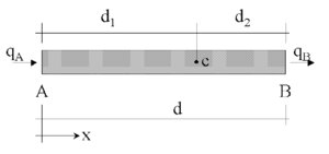
|
| Figure 1: Equilibrium of fluxes in a balance domain of finite size |

|
| Figure 2: Reference surface for the wave height |

|
| Figure 3: Definition of free-surface parameters |
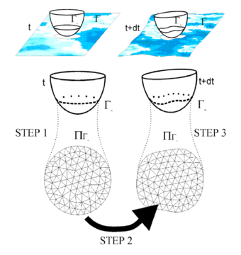
|
| Figure 4: Changes on the fluid interface in a floating body |
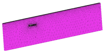
|
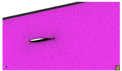
|
| a) | |
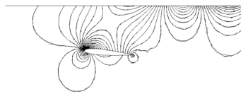
| |
| b) | |
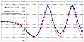
| |
| c) | |
| Figure 5: Submerged NACA0012 profile. a) Detail of the mesh of 70000 linear tetrahedra chosen. b) Pressure contours. c) Stationary wave profile | |
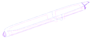
|
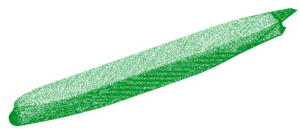
|
| Figure 7: KVLCC2 model. Geometrical definition based on NURBS surfaces and surface mesh used in the analysis |
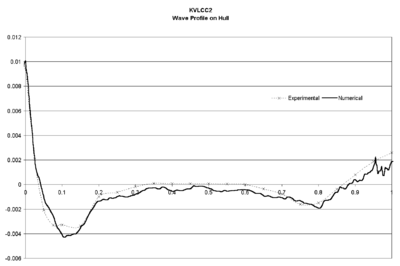
|
| Figure 8: KVLCC2 model. Wave profile on the hull. Thick line shows numerical results |
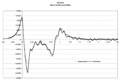
|
| Figure 9: KVLCC2 model. Wave profile on a cut at y/L=0.0964. Thick line shows numerical results |
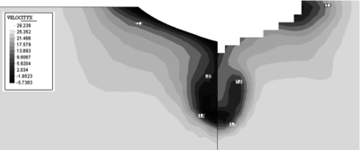
|
| Figure 10: KVLCC2 model. Map of the X component of the velocity on a plane at 2.71 m from the orthogonal aft. Experimental data shown in the right |
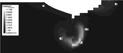
|
| Figure 11: KVLCC2 model. Map of the eddy kinetic energy () on a plane at 2.71 m from the orthogonal aft. Experimental data shown in the right |
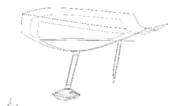
|
| Figure 12: NURBS-based geometry used in the analysis of the Rioja de España America Cup boat |
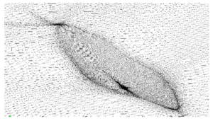
|
| Figure 13: Detail of the final (boundary) mesh used in the E0D0 case. The mesh has been adapted taking into account sinkage, trim and free-surface deformation |
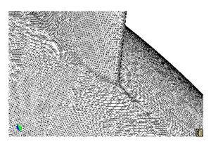
|
| Figure 14: Detail of the mesh used in the analysis of the E0D0 case, around keel-bulb union |
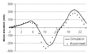
|
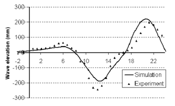
|
| Figure 15: Wave elevation profile for 10kn (left: E0D0, right: E15D2) | |
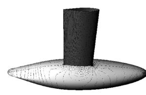
|
| Figure 16: E0D0 8kn. Pressure contours on bulb |
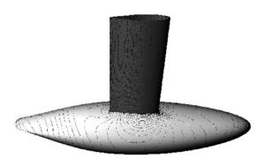
|
| Figure 17: E25D2 8kn. Pressure contours on bulb |
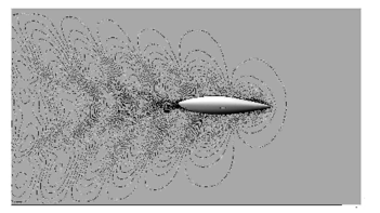
|
| Figure 18: E15D2 9kn Wave map |
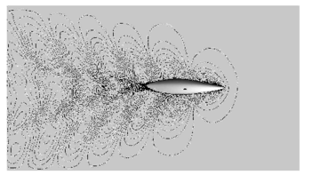
|
| Figure 19: E25D2 9kn Wave map |
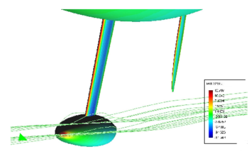
|
| Figure 20: E15D2 7.5 kn. Pressure map on appendages and streamlines. Perspective view |
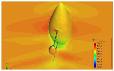
|
| Figure 21:E15D4 7.5 kn. Velocity modulus contours. Perspective view |
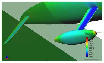
|
| Figure 22:E25D2 7.5 kn. Pressure contours on appendages and cuts. Perspective view |
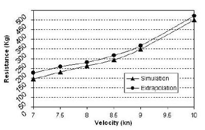
|
| Figure 23:E0D0. Resistance graph. Comparison with results extrapolated from experimental data |
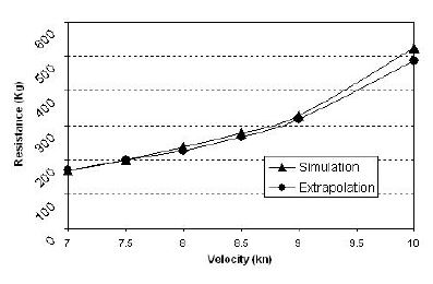
|
| Figure 24:E15D4. Resistance graph. Comparison with results extrapolated from experimental data |
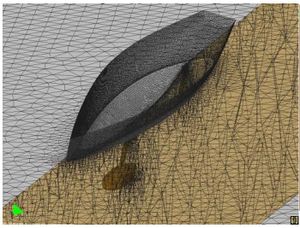
|
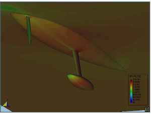
|
| a) | b) |
| Figure 25:American Cup Bravo España racing sail boat. a) Mesh used in the analysis. b) Velocity contours | |
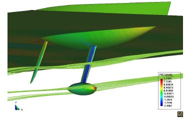
|
| Figure 26:Bravo España. Streamlines |
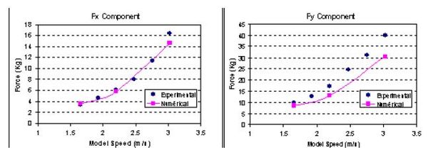
|
| Figure 27:Bravo España. Resistance test. Comparison of numerical results with experimental data |

|

|

|

|

|

|

|

|

|

|

|

|

|

|
| Figure 28: Fixed ship hit by incoming wave | |

|

|

|

|

|

|

|

|

|

|

|

|

|

|
| Figure 29: Moving ship with fixed velocity | |
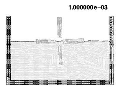
|
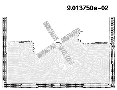
|
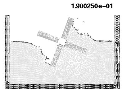
|
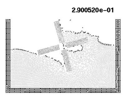
|
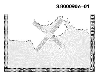
|
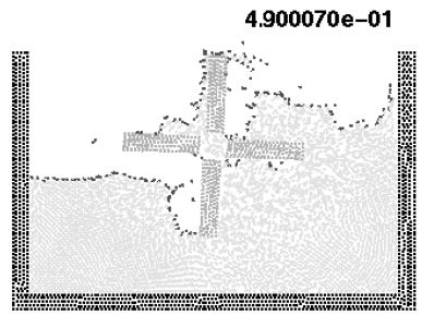
|
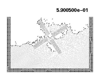
|
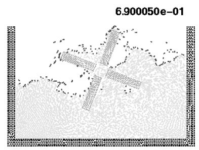
|
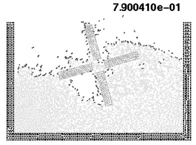
|
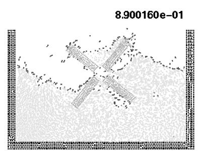
|
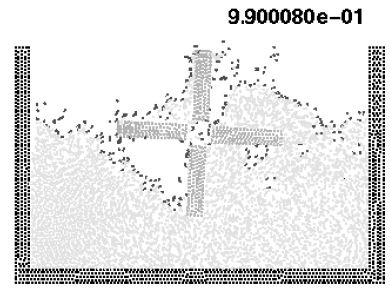
|
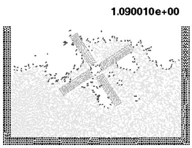
|
| Figure 30:Rotating water mill. | ||
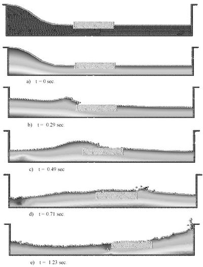
|
| Figure 31:Floating wood piece hit by a wave |
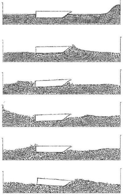
|
| Figure 32:Motion of a rigid ship hit by an incoming wave. The ship is modelled as a rigid solid restrained to move in the vertical direction. |
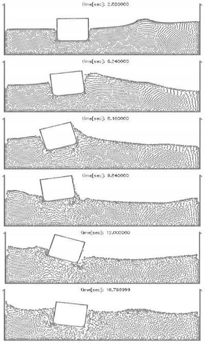
|
| Figure 33:Ship with stabilizers hit by a lateral wave |
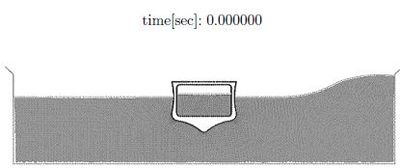
|
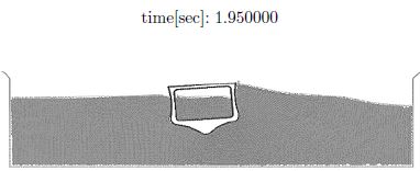
|
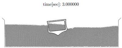
|
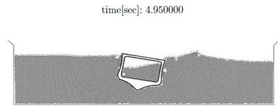
|
| Figure 34:Tanks hip carrying an internal liquid hit by wave. Ship and fluids motion at different time steps |
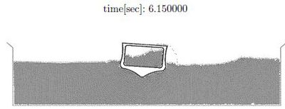
|
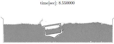
|
| Figure 34:Cont. |
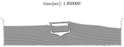
|
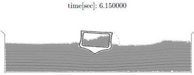
|
| Figure 35:Tanks hip under lateral wave. Pressure distribution at two time steps |
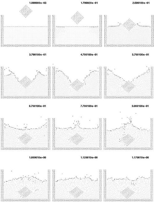
|
| Figure 36:Solid cube falling into a recipient with water. The cube is modelled as a very viscous fluid. |
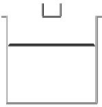
|
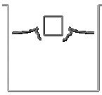
|
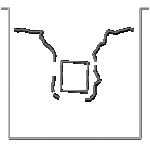
|
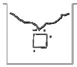
|
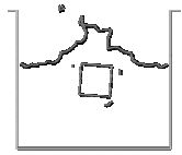
|
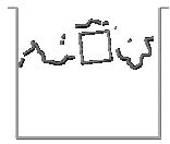
|
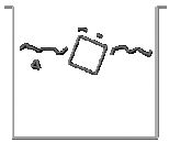
|
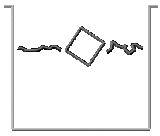
|
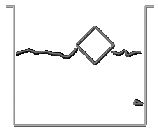
|
| Figure 37:Cube falling into a recipient with water. The cube is modelled as a rigid solid. Motion of the cube and free surface positions at different time steps. | ||
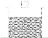
|
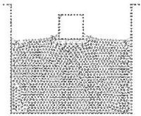
|
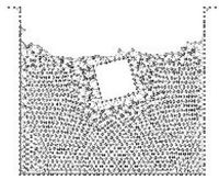
|
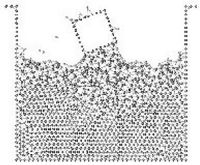
|
| Figure 38:Cube falling in a water recipient. The cube is modeled as a rigid solid. The finite element meshes generated at the selected instants are shown. | |
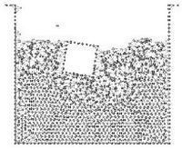
|
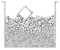
|
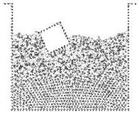
|
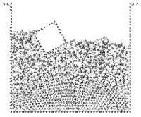
|
| Figure 38:cont | |
