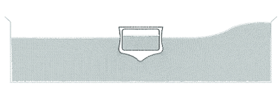
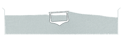
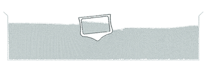
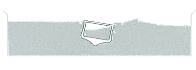
m (Move page script moved page Draft Samper 860628002 to Onate et al 2004g) |
|||
| (87 intermediate revisions by one other user not shown) | |||
| Line 20: | Line 20: | ||
Most of these problems disappear if a ''Lagrangian description'' is used to formulate the governing equations of both the solid and the fluid domain. In the Lagrangian formulation the motion of the individual particles are followed and, consequently, nodes in a finite element mesh can be viewed as moving “particles”. Hence, the motion of the mesh discretizing the total domain (including both the fluid and solid parts) is followed during the transient solution. | Most of these problems disappear if a ''Lagrangian description'' is used to formulate the governing equations of both the solid and the fluid domain. In the Lagrangian formulation the motion of the individual particles are followed and, consequently, nodes in a finite element mesh can be viewed as moving “particles”. Hence, the motion of the mesh discretizing the total domain (including both the fluid and solid parts) is followed during the transient solution. | ||
| − | In this paper we present an overview of a particular class of Lagrangian formulation developed by the authors to solve problems involving the interaction between fluids and solids in a unified manner. The method, called the ''particle finite element method'' (PFEM), treats the mesh nodes in the fluid and solid domains as particles which can freely move and even separate from the main fluid domain representing, for instance, the effect of water drops. A finite element mesh connects the nodes defining the discretized domain where the governing equations are solved in the standard FEM fashion. The PFEM is the natural evolution of recent work of the authors for the solution of FSI problems using Lagrangian finite element and meshless methods [Aubry ''et al.'' (2004) <span id="citeF-1"></span>[[#cite-1|[1]]]; Idelsohn ''et al.'' (2003a; 2003b; 2004) <span id="citeF-20"></span>[[#cite-20|[20]],<span id="citeF-21"></span>[[#cite-21|21]],<span id="citeF-23"></span>[[#cite-23|23]]]; Oñate ''et al.'' (2003; 2004)<span id="citeF-33"></span>[[#cite-33|[33]],<span id="citeF-34"></span>[[#cite-34|34]]]]. | + | In this paper we present an overview of a particular class of Lagrangian formulation developed by the authors to solve problems involving the interaction between fluids and solids in a unified manner. The method, called the ''particle finite element method'' (PFEM), treats the mesh nodes in the fluid and solid domains as particles which can freely move and even separate from the main fluid domain representing, for instance, the effect of water drops. A finite element mesh connects the nodes defining the discretized domain where the governing equations are solved in the standard FEM fashion. The PFEM is the natural evolution of recent work of the authors for the solution of FSI problems using Lagrangian finite element and meshless methods [Aubry ''et al.'' (2004) <span id="citeF-1"></span>[[#cite-1|[1]]]; Idelsohn ''et al.'' (2003a; 2003b; 2004) <span id="citeF-20"></span>[[#cite-20|[20]],<span id="citeF-21"></span>[[#cite-21|21]],<span id="citeF-23"></span>[[#cite-23|23]]]; Oñate ''et al.'' (2003; 2004) <span id="citeF-33"></span>[[#cite-33|[33]],<span id="citeF-34"></span>[[#cite-34|34]]]]. |
| − | An obvious advantage of the Lagrangian formulation is that the convective terms disappear from the fluid equations. The difficulty is however transferred to the problem of adequately (and efficiently) moving the mesh nodes. Indeed for large mesh motions remeshing may be a frequent necessity along the time solution. We use an innovative mesh regeneration procedure blending elements of different shapes using an extended Delaunay tesselation [Idelsohn ''et al.'' (2003a; 2003c)<span id="citeF-20"></span>[[#cite-20|[20]],<span id="citeF-22"></span>[[#cite-22|22]]]. Furthermore, this special polyhedral finite element needs special shape funtions. In this paper, meshless finite element (MFEM) shape functions have been used [Idelsohn ''et al.'' (2003a)<span id="citeF-20"></span>[[#cite-20|[20]]]]. | + | An obvious advantage of the Lagrangian formulation is that the convective terms disappear from the fluid equations. The difficulty is however transferred to the problem of adequately (and efficiently) moving the mesh nodes. Indeed for large mesh motions remeshing may be a frequent necessity along the time solution. We use an innovative mesh regeneration procedure blending elements of different shapes using an extended Delaunay tesselation [Idelsohn ''et al.'' (2003a; 2003c) <span id="citeF-20"></span>[[#cite-20|[20]],<span id="citeF-22"></span>[[#cite-22|22]]]. Furthermore, this special polyhedral finite element needs special shape funtions. In this paper, meshless finite element (MFEM) shape functions have been used [Idelsohn ''et al.'' (2003a) <span id="citeF-20"></span>[[#cite-20|[20]]]]. |
| − | The need to properly treat the incompressibility condition in the fluid still remains in the Lagrangian formulation. The use of standard finite element interpolations may lead to a volumetric locking defect unless some precautions are taken. A number of stabilization finite element procedures aiming to alleviate the locking problem in incompressible fluids have been proposed and some of them are listed in [Chorin (1967)<span id="citeF-2"></span>[[#cite-2|[2]]]; Codina (2002)<span id="citeF-3"></span>[[#cite-3|[3]]]; Codina ''et al.'' (1998)<span id="citeF-4"></span>[[#cite-4|[4]]]; Codina and Blasco (2000)<span id="citeF-5"></span>[[#cite-5|[5]]]; Codina and Zienkiewicz (2002)<span id="citeF-6"></span>[[#cite-6|[6]]]; Cruchaga and Oñate (1997; 1999)<span id="citeF-7"></span>[[#cite-7|[7]],<span id="citeF-8"></span>[[#cite-8|8]]]; Donea and Huerta (2003)<span id="citeF-9"></span>[[#cite-9|[9]]]; Franca and Frey (1992)<span id="citeF-11"></span>[[#cite-11|[11]]]; Hansbo and Szepessy (1990)<span id="citeF- | + | The need to properly treat the incompressibility condition in the fluid still remains in the Lagrangian formulation. The use of standard finite element interpolations may lead to a volumetric locking defect unless some precautions are taken. A number of stabilization finite element procedures aiming to alleviate the locking problem in incompressible fluids have been proposed and some of them are listed in [Chorin (1967) <span id="citeF-2"></span>[[#cite-2|[2]]]; Codina (2002) <span id="citeF-3"></span>[[#cite-3|[3]]]; Codina ''et al.'' (1998) <span id="citeF-4"></span>[[#cite-4|[4]]]; Codina and Blasco (2000) <span id="citeF-5"></span>[[#cite-5|[5]]]; Codina and Zienkiewicz (2002) <span id="citeF-6"></span>[[#cite-6|[6]]]; Cruchaga and Oñate (1997; 1999) <span id="citeF-7"></span>[[#cite-7|[7]],<span id="citeF-8"></span>[[#cite-8|8]]]; Donea and Huerta (2003) <span id="citeF-9"></span>[[#cite-9|[9]]]; Franca and Frey (1992) <span id="citeF-11"></span>[[#cite-11|[11]]]; Hansbo and Szepessy (1990) <span id="citeF-15"></span>[[#cite-15|[15]]]; Hughes ''et al.'' (1986; 1989; 1994) <span id="citeF-16"></span>[[#cite-16|[16]],<span id="citeF-17"></span>[[#cite-17|17]],<span id="citeF-18"></span>[[#cite-18|18]]]; Oñate (1998) <span id="citeF-27"></span>[[#cite-27|[27]]]; Sheng ''et al.'' (1996) <span id="citeF-36"></span>[[#cite-36|[36]]]; Tezduyar ''et al.'' (1992) <span id="citeF-41"></span>[[#cite-41|[41]]]; Zienkiewicz and Taylor (2000) <span id="citeF-43"></span>[[#cite-43|[43]]]; Storti ''et al.'' (2004) <span id="citeF-37"></span>[[#cite-37|[37]]]]. A general aim is to use low order elements with equal order interpolation for the velocity and pressure variables. In our work the stabilization via a finite calculus (FIC) procedure has been chosen [Oñate (2000) <span id="citeF-28"></span>[[#cite-28|[28]]]]. Recent applications of the FIC method for incompressible flow analysis using linear triangles and tetrahedra are reported in [García and Oñate (2003) <span id="citeF-12"></span>[[#cite-12|[12]]]; Oñate (2004) <span id="citeF-29"></span>[[#cite-29|[29]]]; Oñate ''et al.'' (2000; 2004) <span id="citeF-31"></span>[[#cite-31|[31]],<span id="citeF-34"></span>[[#cite-34|34]]]; Oñate and García (2001) <span id="citeF-32"></span>[[#cite-32|[32]]]; Oñate and Idelsohn (1998) <span id="citeF-30"></span>[[#cite-30|[30]]]]. |
| − | The Lagrangian formulation has many advantages for tracking the motion of fluid particles in flows accounting for large displacements of the fluid surface as in the case of breaking waves and splashing of liquids (Figure [[#img-1|1]]). We note that the information in the PFEM is typically nodal-based, i.e. the element mesh is mainly used to obtain the values of the state variables (i.e. velocities, pressure, etc.) at the nodes. A difficulty arises in the identification of the boundary of the domain from a given collection of nodes. Indeed the “boundary” can include the free surface in the fluid and the individual particles moving outside the fluid domain. In our work the Alpha Shape technique [Edelsbrunner and Mucke (1999)<span id="citeF-10"></span>[[#cite-10|[10]]]] is used to identify the boundary nodes. | + | The Lagrangian formulation has many advantages for tracking the motion of fluid particles in flows accounting for large displacements of the fluid surface as in the case of breaking waves and splashing of liquids (Figure [[#img-1|1]]). We note that the information in the PFEM is typically nodal-based, i.e. the element mesh is mainly used to obtain the values of the state variables (i.e. velocities, pressure, etc.) at the nodes. A difficulty arises in the identification of the boundary of the domain from a given collection of nodes. Indeed the “boundary” can include the free surface in the fluid and the individual particles moving outside the fluid domain. In our work the Alpha Shape technique [Edelsbrunner and Mucke (1999) <span id="citeF-10"></span>[[#cite-10|[10]]]] is used to identify the boundary nodes. |
<div id='img-1'></div> | <div id='img-1'></div> | ||
| Line 42: | Line 42: | ||
Let us consider a domain containing both fluid and solid subdomains. The moving fluid particles interact with the solid boundaries thereby inducing the deformation of the solid which in turn affects the flow motion and, therefore, the problem is fully coupled. | Let us consider a domain containing both fluid and solid subdomains. The moving fluid particles interact with the solid boundaries thereby inducing the deformation of the solid which in turn affects the flow motion and, therefore, the problem is fully coupled. | ||
| − | FSI problems traditionally have been solved using an arbitrary Eulerian-Lagrangian description (ALE) for the flow equation whereas the structure is modelled with a full Lagrangian formulation. Many examples of applications of this type of approach are found in the literature. A good review can be found in [Donea and Huerta (2003)<span id="citeF-9"></span>[[#cite-9|[9]]]; Zienkiewicz and Taylor (2000)<span id="citeF-43"></span>[[#cite-43|[43]]]]. | + | FSI problems traditionally have been solved using an arbitrary Eulerian-Lagrangian description (ALE) for the flow equation whereas the structure is modelled with a full Lagrangian formulation. Many examples of applications of this type of approach are found in the literature. A good review can be found in [Donea and Huerta (2003) <span id="citeF-9"></span>[[#cite-9|[9]]]; Zienkiewicz and Taylor (2000) <span id="citeF-43"></span>[[#cite-43|[43]]]]. |
In the PFEM approach presented here, both the fluid and the solid domains are modelled using an ''updated'' ''Lagrangian formulation''. The finite element method (FEM) is used to solve the continuum equations in both domains. Hence a mesh discretizing these domains must be generated in order to solve the governing equations for both the fluid and solid problems in the standard FEM fashion. We note once more that the nodes discretizing the fluid and solid domains can be viewed as material particles which motion is tracked during the transient solution. | In the PFEM approach presented here, both the fluid and the solid domains are modelled using an ''updated'' ''Lagrangian formulation''. The finite element method (FEM) is used to solve the continuum equations in both domains. Hence a mesh discretizing these domains must be generated in order to solve the governing equations for both the fluid and solid problems in the standard FEM fashion. We note once more that the nodes discretizing the fluid and solid domains can be viewed as material particles which motion is tracked during the transient solution. | ||
| Line 54: | Line 54: | ||
<ol> | <ol> | ||
| − | <li>Discretize the fluid and solid domains with a finite element mesh. The mesh generation process can be based on a standard Delaunay discretization [George (1991)<span id="citeF-13"></span>[[#cite-13|[13]]]] of the analysis domain using an initial collection of points which then become the mesh nodes. Alternatively, the nodes can be created during the mesh generation process using a front generation method [Irons (1970)<span id="citeF-24"></span>[[#cite-24|[24]]]; Thompson ''et al.'' (1999)<span id="citeF-42"></span>[[#cite-42|[42]]]]. </li> | + | <li>Discretize the fluid and solid domains with a finite element mesh. The mesh generation process can be based on a standard Delaunay discretization [George (1991) <span id="citeF-13"></span>[[#cite-13|[13]]]] of the analysis domain using an initial collection of points which then become the mesh nodes. Alternatively, the nodes can be created during the mesh generation process using a front generation method [Irons (1970) <span id="citeF-24"></span>[[#cite-24|[24]]]; Thompson ''et al.'' (1999) <span id="citeF-42"></span>[[#cite-42|[42]]]]. </li> |
| − | <li>Identify the external boundaries for both the fluid and solid domains. This is an essential step as some boundaries (such as the free surface in fluids) may be severely distorted during the solution process including separation and re-entering of nodes. The Alpha Shape method [Edelsbrunner and Mucke (2003)<span id="citeF-10"></span>[[#cite-10|[10]]]] is used for the boundary definition (see Section [[#7 Generation of a New Mesh|7]]). </li> | + | <li>Identify the external boundaries for both the fluid and solid domains. This is an essential step as some boundaries (such as the free surface in fluids) may be severely distorted during the solution process including separation and re-entering of nodes. The Alpha Shape method [Edelsbrunner and Mucke (2003) <span id="citeF-10"></span>[[#cite-10|[10]]]] is used for the boundary definition (see Section [[#7 Generation of a New Mesh|7]]). </li> |
<li>Solve the coupled Lagrangian equations of motion for the fluid and the solid domains. Compute the relevant state variables in both domains at each time step: velocities, pressure and viscous stresses in the fluid and displacements, stresses and strains in the solid. </li> | <li>Solve the coupled Lagrangian equations of motion for the fluid and the solid domains. Compute the relevant state variables in both domains at each time step: velocities, pressure and viscous stresses in the fluid and displacements, stresses and strains in the solid. </li> | ||
<li>Move the mesh nodes to a new position in terms of the time increment size. This step is typically a consequence of the solution process of step 3. </li> | <li>Move the mesh nodes to a new position in terms of the time increment size. This step is typically a consequence of the solution process of step 3. </li> | ||
| − | <li>Generate a new mesh if needed. The mesh regeneration process can take place after a prescribed number of time steps or when the actual mesh has suffered severe distorsions due to the Lagrangian motion. In our work we use an innovative mesh generation scheme based on the extended Delaunay tesselation (Section [[#7 Generation of a New Mesh|7]]) [Idelsohn ''et al.'' (2003a; 2003b; 2004)<span id="citeF-20"></span>[[#cite-20|[20]],<span id="citeF-21"></span>[[#cite-21|21]],<span id="citeF-23"></span>[[#cite-23|23]]]]. </li> | + | <li>Generate a new mesh if needed. The mesh regeneration process can take place after a prescribed number of time steps or when the actual mesh has suffered severe distorsions due to the Lagrangian motion. In our work we use an innovative mesh generation scheme based on the extended Delaunay tesselation (Section [[#7 Generation of a New Mesh|7]]) [Idelsohn ''et al.'' (2003a; 2003b; 2004) <span id="citeF-20"></span>[[#cite-20|[20]],<span id="citeF-21"></span>[[#cite-21|21]],<span id="citeF-23"></span>[[#cite-23|23]]]]. </li> |
<li>Go back to step 2 and repeat the solution process for the next time step. </li> | <li>Go back to step 2 and repeat the solution process for the next time step. </li> | ||
| Line 70: | Line 70: | ||
{| class="floating_imageSCP" style="text-align: center; border: 1px solid #BBB; margin: 1em auto; width: 100%;max-width: 100%;" | {| class="floating_imageSCP" style="text-align: center; border: 1px solid #BBB; margin: 1em auto; width: 100%;max-width: 100%;" | ||
|- style="text-align: center; font-size: 75%;" | |- style="text-align: center; font-size: 75%;" | ||
| − | | colspan="1"|(a) | + | | colspan="1" |(a) |
| − | | colspan="1"|(b) | + | | colspan="1" |(b) |
|- | |- | ||
| − | |[[ | + | |[[File:Draft_Samper_860628002_8660_2a.JPG]] |
| + | |[[File:Draft_Samper_860628002_1006_2b.JPG]] | ||
|- | |- | ||
| − | |[[Image:draft_Samper_616988227-Figure2c.png|300px|Breakage of a water column. (a) Discretization of the fluid domain and the solid walls. Boundary nodes are marked with circles. (b) and (c) Mesh in the fluid and solid domains at two different times.]] | + | | colspan="2" |[[Image:draft_Samper_616988227-Figure2c.png|300px|Breakage of a water column. (a) Discretization of the fluid domain and the solid walls. Boundary nodes are marked with circles. (b) and (c) Mesh in the fluid and solid domains at two different times.]] |
|- style="text-align: center; font-size: 75%;" | |- style="text-align: center; font-size: 75%;" | ||
| − | | colspan="2"|(c) | + | | colspan="2" |(c) |
|- style="text-align: center; font-size: 75%;" | |- style="text-align: center; font-size: 75%;" | ||
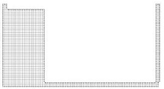
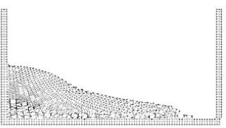
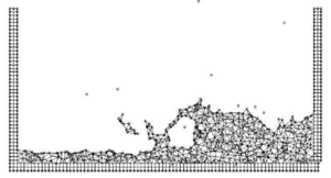
| colspan="2" | '''Figure 2:''' Breakage of a water column. (a) Discretization of the fluid domain and the solid walls. Boundary nodes are marked with circles. (b) and (c) Mesh in the fluid and solid domains at two different times. | | colspan="2" | '''Figure 2:''' Breakage of a water column. (a) Discretization of the fluid domain and the solid walls. Boundary nodes are marked with circles. (b) and (c) Mesh in the fluid and solid domains at two different times. | ||
| Line 84: | Line 85: | ||
==3 Lagrangian Equations for an Incompressible Fluid. FIC Formulation== | ==3 Lagrangian Equations for an Incompressible Fluid. FIC Formulation== | ||
| − | The standard infinitessimal equations for a viscous incompressible fluid can be written in a Lagrangian frame as [Oñate (1998); Zienkiewicz and Taylor (2000) | + | The standard infinitessimal equations for a viscous incompressible fluid can be written in a Lagrangian frame as [Oñate (1998) <span id="citeF-27"></span>[[#cite-27|[27]]]; Zienkiewicz and Taylor (2000) <span id="citeF-43"></span>[[#cite-43|[43]]]] |
| − | + | ||
| − | + | ||
| + | '''Momentum''' | ||
| + | <span id="eq-1"></span> | ||
{| class="formulaSCP" style="width: 100%; text-align: left;" | {| class="formulaSCP" style="width: 100%; text-align: left;" | ||
|- | |- | ||
| Line 98: | Line 99: | ||
|} | |} | ||
| − | + | '''Mass balance''' | |
| − | + | <span id="eq-2"></span> | |
{| class="formulaSCP" style="width: 100%; text-align: left;" | {| class="formulaSCP" style="width: 100%; text-align: left;" | ||
|- | |- | ||
| Line 111: | Line 112: | ||
where | where | ||
| − | + | <span id="eq-3"></span> | |
{| class="formulaSCP" style="width: 100%; text-align: left;" | {| class="formulaSCP" style="width: 100%; text-align: left;" | ||
|- | |- | ||
| Line 118: | Line 119: | ||
|- | |- | ||
| style="text-align: center;" | <math>r_{m_i} = \rho {\partial v_i \over \partial t} + {\partial \sigma _{ij} \over \partial x_j}-b_i\quad ,\quad \sigma _{ji}=\sigma _{ij}</math> | | style="text-align: center;" | <math>r_{m_i} = \rho {\partial v_i \over \partial t} + {\partial \sigma _{ij} \over \partial x_j}-b_i\quad ,\quad \sigma _{ji}=\sigma _{ij}</math> | ||
| + | |} | ||
| style="width: 5px;text-align: right;white-space: nowrap;" | (3) | | style="width: 5px;text-align: right;white-space: nowrap;" | (3) | ||
| + | |} | ||
| + | |||
| + | <span id="eq-4"></span> | ||
| + | {| class="formulaSCP" style="width: 100%; text-align: left;" | ||
| + | |- | ||
| + | | | ||
| + | {| style="text-align: left; margin:auto;width: 100%;" | ||
|- | |- | ||
| style="text-align: center;" | <math> r_d = {\partial v_i \over \partial x_i}\qquad i,j = 1, n_d </math> | | style="text-align: center;" | <math> r_d = {\partial v_i \over \partial x_i}\qquad i,j = 1, n_d </math> | ||
| + | |} | ||
| style="width: 5px;text-align: right;white-space: nowrap;" | (4) | | style="width: 5px;text-align: right;white-space: nowrap;" | (4) | ||
| − | |||
|} | |} | ||
Above <math display="inline">n_d</math> is the number of space dimensions, <math display="inline">v_i</math> is the velocity along the ith global axis (<math display="inline">v_i = {\partial u_i \over \partial t}</math>, where <math display="inline">u_i</math> is the ''i''th displacement), <math display="inline">\rho </math> is the (constant) density of the fluid, <math display="inline">b_i</math> are the body forces, <math display="inline">\sigma _{ij}</math> are the total stresses given by <math display="inline">\sigma _{ij}=s_{ij}-\delta _{ij}p</math>, <math display="inline">p</math> is the absolute pressure (defined positive in compression) and <math display="inline">s_{ij}</math> are the viscous deviatoric stresses related to the viscosity <math display="inline">\mu </math> by the standard expression | Above <math display="inline">n_d</math> is the number of space dimensions, <math display="inline">v_i</math> is the velocity along the ith global axis (<math display="inline">v_i = {\partial u_i \over \partial t}</math>, where <math display="inline">u_i</math> is the ''i''th displacement), <math display="inline">\rho </math> is the (constant) density of the fluid, <math display="inline">b_i</math> are the body forces, <math display="inline">\sigma _{ij}</math> are the total stresses given by <math display="inline">\sigma _{ij}=s_{ij}-\delta _{ij}p</math>, <math display="inline">p</math> is the absolute pressure (defined positive in compression) and <math display="inline">s_{ij}</math> are the viscous deviatoric stresses related to the viscosity <math display="inline">\mu </math> by the standard expression | ||
| − | + | <span id="eq-5"></span> | |
{| class="formulaSCP" style="width: 100%; text-align: left;" | {| class="formulaSCP" style="width: 100%; text-align: left;" | ||
|- | |- | ||
| Line 138: | Line 147: | ||
where <math display="inline">\delta _{ij}</math> is the Kronecker delta and the strain rates <math display="inline">\dot \varepsilon _{ij}</math> are | where <math display="inline">\delta _{ij}</math> is the Kronecker delta and the strain rates <math display="inline">\dot \varepsilon _{ij}</math> are | ||
| − | + | <span id="eq-6"></span> | |
{| class="formulaSCP" style="width: 100%; text-align: left;" | {| class="formulaSCP" style="width: 100%; text-align: left;" | ||
|- | |- | ||
| Line 151: | Line 160: | ||
In the above all variables are defined at the current time <math display="inline">t</math> (current configuration). | In the above all variables are defined at the current time <math display="inline">t</math> (current configuration). | ||
| − | In our work we will solve a ''modified set of governing'' equations derived using a finite calculus (FIC) formulation. The FIC governing equations are [Oñate (1998; 2000; 2004); Oñate ''et al.'' (2001) | + | In our work we will solve a ''modified set of governing'' equations derived using a finite calculus (FIC) formulation. The FIC governing equations are [Oñate (1998; 2000; 2004) <span id="citeF-27"></span>[[#cite-27|[27]],<span id="citeF-28"></span>[[#cite-28|28]],<span id="citeF-29"></span>[[#cite-29|29]]]; Oñate ''et al.'' (2001) <span id="citeF-32"></span>[[#cite-32|[32]]]] |
| − | + | ||
| − | + | ||
| + | '''Momentum''' | ||
| + | <span id="eq-7"></span> | ||
{| class="formulaSCP" style="width: 100%; text-align: left;" | {| class="formulaSCP" style="width: 100%; text-align: left;" | ||
|- | |- | ||
| Line 160: | Line 169: | ||
{| style="text-align: left; margin:auto;width: 100%;" | {| style="text-align: left; margin:auto;width: 100%;" | ||
|- | |- | ||
| − | | style="text-align: center;" | <math>r_{m_i} - \underline{{1\over 2} h_j{\partial r_{m_i} \over \partial x_j} | + | | style="text-align: center;" | <math>r_{m_i} - \underline{{1\over 2} h_j{\partial r_{m_i} \over \partial x_j}}=0 </math> |
|} | |} | ||
| style="width: 5px;text-align: right;white-space: nowrap;" | (7) | | style="width: 5px;text-align: right;white-space: nowrap;" | (7) | ||
|} | |} | ||
| − | + | '''Mass balance''' | |
| − | + | <span id="eq-8"></span> | |
{| class="formulaSCP" style="width: 100%; text-align: left;" | {| class="formulaSCP" style="width: 100%; text-align: left;" | ||
|- | |- | ||
| Line 172: | Line 181: | ||
{| style="text-align: left; margin:auto;width: 100%;" | {| style="text-align: left; margin:auto;width: 100%;" | ||
|- | |- | ||
| − | | style="text-align: center;" | <math>r_d - \underline{{1\over 2} h_j {\partial r_d \over \partial x_j} | + | | style="text-align: center;" | <math>r_d - \underline{{1\over 2} h_j {\partial r_d \over \partial x_j}}=0 </math> |
|} | |} | ||
| style="width: 5px;text-align: right;white-space: nowrap;" | (8) | | style="width: 5px;text-align: right;white-space: nowrap;" | (8) | ||
|} | |} | ||
| − | + | <span id="eq-9"></span> | |
The problem definition is completed with the following boundary conditions | The problem definition is completed with the following boundary conditions | ||
| Line 184: | Line 193: | ||
{| style="text-align: left; margin:auto;width: 100%;" | {| style="text-align: left; margin:auto;width: 100%;" | ||
|- | |- | ||
| − | | style="text-align: center;" | <math>n_j \sigma _{ij} -t_i + \underline{{1\over 2} h_j n_j r_{m_i} | + | | style="text-align: center;" | <math>n_j \sigma _{ij} -t_i + \underline{{1\over 2} h_j n_j r_{m_i}}=0 \quad \hbox{on }\Gamma _t </math> |
|} | |} | ||
| style="width: 5px;text-align: right;white-space: nowrap;" | (9) | | style="width: 5px;text-align: right;white-space: nowrap;" | (9) | ||
|} | |} | ||
| − | + | <span id="eq-10"></span> | |
{| class="formulaSCP" style="width: 100%; text-align: left;" | {| class="formulaSCP" style="width: 100%; text-align: left;" | ||
|- | |- | ||
| Line 201: | Line 210: | ||
and the initial condition is <math display="inline">v_j =v_j^0</math> for <math display="inline">t=t_0</math>. The standard summation convention for repeated indexes is assumed unless otherwise specified. | and the initial condition is <math display="inline">v_j =v_j^0</math> for <math display="inline">t=t_0</math>. The standard summation convention for repeated indexes is assumed unless otherwise specified. | ||
| − | In Eqs.(7) and (8) <math display="inline">t_i</math> and <math display="inline">v_j^p</math> are surface tractions and prescribed velocities on the boundaries <math display="inline">\Gamma _t</math> and <math display="inline">\Gamma _v</math>, respectively, <math display="inline">n_j</math> are the components of the unit normal vector to the boundary. | + | In Eqs.([[#eq-7|7]]) and ([[#eq-8|8]]) <math display="inline">t_i</math> and <math display="inline">v_j^p</math> are surface tractions and prescribed velocities on the boundaries <math display="inline">\Gamma _t</math> and <math display="inline">\Gamma _v</math>, respectively, <math display="inline">n_j</math> are the components of the unit normal vector to the boundary. |
| − | The <math display="inline">h_i's</math> in above equations are ''characteristic lengths'' of the domain where balance of momentum and mass is enforced. In Eq.(9) these lengths define the domain where equilibrium of boundary tractions is established. Details of the derivation of Eqs.(7)–(10) can be found in [Oñate (1998; 2000); Oñate ''et al.'' (2001)]. | + | The <math display="inline">h_i's</math> in above equations are ''characteristic lengths'' of the domain where balance of momentum and mass is enforced. In Eq.([[#eq-9|9]]) these lengths define the domain where equilibrium of boundary tractions is established. Details of the derivation of Eqs.([[#eq-7|7]])–([[#eq-10|10]]) can be found in [Oñate (1998; 2000) <span id="citeF-27"></span>[[#cite-27|[27]],<span id="citeF-28"></span>[[#cite-28|28]]]; Oñate ''et al.'' (2001) <span id="citeF-32"></span>[[#cite-32|[32]]]]. |
| − | Eqs.(7)–(10) are the starting point for deriving stabilized finite element methods to solve the incompressible Navier-Stokes equations in a Lagrangian frame of reference using equal order interpolation for the velocity and pressure variables [Idelsohn ''et al.'' (2002; 2003a; 2003b; 2004); Oñate ''et al.'' (2003); Aubry ''et al.'' (2004)]. Application of the FIC formulation to finite element and meshless analysis of fluid flow problems can be found in [García and Oñate (2003); Oñate (2000; 2004); Oñate ''et al.'' (2000; 2004); Oñate and García (2001); Oñate and Idelsohn ( | + | Eqs.([[#eq-7|7]])–([[#eq-10|10]]) are the starting point for deriving stabilized finite element methods to solve the incompressible Navier-Stokes equations in a Lagrangian frame of reference using equal order interpolation for the velocity and pressure variables [Idelsohn ''et al.'' (2002; 2003a; 2003b; 2004) <span id="citeF-19"></span>[[#cite-19|[19]]-<span id="citeF-21"></span>[[#cite-21|21]],<span id="citeF-23"></span>[[#cite-23|23]]]; Oñate ''et al.'' (2003) <span id="citeF-33"></span>[[#cite-33|[33]]]; Aubry ''et al.'' (2004) <span id="citeF-1"></span>[[#cite-1|[1]]]]. Application of the FIC formulation to finite element and meshless analysis of fluid flow problems can be found in [García and Oñate (2003 <span id="citeF-12"></span>[[#cite-12|[12]]]); Oñate (2000; 2004) <span id="citeF-28"></span>[[#cite-28|[28]],<span id="citeF-29"></span>[[#cite-29|29]]]; Oñate ''et al.'' (2000; 2004) <span id="citeF-31"></span>[[#cite-31|[31]],<span id="citeF-34"></span>[[#cite-34|34]]]; Oñate and García (2001) <span id="citeF-32"></span>[[#cite-32|[32]]]; Oñate and Idelsohn (1998) <span id="citeF-30"></span>[[#cite-30|[30]]]]. |
===3.1 Transformation of the mass balance equation. Integral governing equations=== | ===3.1 Transformation of the mass balance equation. Integral governing equations=== | ||
| − | The underlined term in Eq.(8) can be expressed in terms of the momentum equations. The new expression for the mass balance equation is (see Appendix) | + | The underlined term in Eq.([[#eq-8|8]]) can be expressed in terms of the momentum equations. The new expression for the mass balance equation is (see [[#Appendix|Appendix]]) |
| − | + | <span id="eq-11"></span> | |
{| class="formulaSCP" style="width: 100%; text-align: left;" | {| class="formulaSCP" style="width: 100%; text-align: left;" | ||
|- | |- | ||
| Line 222: | Line 231: | ||
with | with | ||
| − | + | <span id="eq-12"></span> | |
{| class="formulaSCP" style="width: 100%; text-align: left;" | {| class="formulaSCP" style="width: 100%; text-align: left;" | ||
|- | |- | ||
| Line 233: | Line 242: | ||
|} | |} | ||
| − | The <math display="inline">\tau _i</math>'s in Eq.(11), when scaled by the density, are termed ''intrinsic time parameters''. Similar values for <math display="inline">\tau _i</math> (usually <math display="inline">\tau _i =\tau </math> is taken) are used in other works from ad-hoc extensions of the 1D advective-diffusive problem [Codina ''et al.'' (1998); Codina and Blasco (2000); Codina (2002); Codina and Zienkiewicz (2002); Cruchaga and Oñate (1997; 1999); Donea and Huerta (2003); Franca and Frey (1992); Hansbo and Szepessy (1990); Hughes ''et al.'' (1986; 1989; 1994); Oñate (1998; 2000; 2004); Sheng ''et al.'' (1996); Storti ''et al.'' ( | + | The <math display="inline">\tau _i</math>'s in Eq.([[#eq-11|11]]), when scaled by the density, are termed ''intrinsic time parameters''. Similar values for <math display="inline">\tau _i</math> (usually <math display="inline">\tau _i =\tau </math> is taken) are used in other works from ad-hoc extensions of the 1D advective-diffusive problem [Codina ''et al.'' (1998) <span id="citeF-4"></span>[[#cite-4|[4]]]; Codina and Blasco (2000) <span id="citeF-5"></span>[[#cite-5|[5]]]; Codina (2002) <span id="citeF-3"></span>[[#cite-3|[3]]]; Codina and Zienkiewicz (2002) <span id="citeF-6"></span>[[#cite-6|[6]]]; Cruchaga and Oñate (1997; 1999) <span id="citeF-7"></span>[[#cite-7|[7]],<span id="citeF-8"></span>[[#cite-8|8]]]; Donea and Huerta (2003) <span id="citeF-9"></span>[[#cite-9|[9]]]; Franca and Frey (1992) <span id="citeF-11"></span>[[#cite-11|[11]]]; Hansbo and Szepessy (1990) <span id="citeF-15"></span>[[#cite-15|[15]]]; Hughes ''et al.'' (1986; 1989; 1994) <span id="citeF-16"></span>[[#cite-16|[16]]-<span id="citeF-18"></span>[[#cite-18|18]]]; Oñate (1998; 2000; 2004) <span id="citeF-27"></span>[[#cite-27|[27]]-<span id="citeF-29"></span>[[#cite-29|29]]]; Sheng ''et al.'' (1996) <span id="citeF-36"></span>[[#cite-36|[36]]]; Storti ''et al.'' (1995) <span id="citeF-37"></span>[[#cite-37|[37]]]; Tezduyar ''et al.'' (1992) <span id="citeF-41"></span>[[#cite-41|[41]]]; Zienkiewicz and Taylor (2000) <span id="citeF-43"></span>[[#cite-43|[43]]]]. |
| − | At this stage it is no longer necessary to retain the stabilization terms in the momentum equations. These terms are critical in Eulerian formulations to stabilize the numerical solution for high values of the convective terms. In the Lagrangian formulation the convective terms dissapear from the momentum equations and the FIC terms in these equations are just useful to derive the form of the mass balance equation given by Eq.(11) and can be disregarded there onwards. Consistenly, the stabilization terms are also neglected in the Neuman boundary conditions (eqs.(9)). | + | At this stage it is no longer necessary to retain the stabilization terms in the momentum equations. These terms are critical in Eulerian formulations to stabilize the numerical solution for high values of the convective terms. In the Lagrangian formulation the convective terms dissapear from the momentum equations and the FIC terms in these equations are just useful to derive the form of the mass balance equation given by Eq.([[#eq-11|11]]) and can be disregarded there onwards. Consistenly, the stabilization terms are also neglected in the Neuman boundary conditions (eqs.([[#eq-9|9]])). |
The weighted residual expression of the final form of the momentum and mass balance equations can be written as | The weighted residual expression of the final form of the momentum and mass balance equations can be written as | ||
| − | + | <span id="eq-13"></span> | |
{| class="formulaSCP" style="width: 100%; text-align: left;" | {| class="formulaSCP" style="width: 100%; text-align: left;" | ||
|- | |- | ||
| Line 248: | Line 257: | ||
| style="width: 5px;text-align: right;white-space: nowrap;" | (13) | | style="width: 5px;text-align: right;white-space: nowrap;" | (13) | ||
|} | |} | ||
| − | + | <span id="eq-14"></span> | |
{| class="formulaSCP" style="width: 100%; text-align: left;" | {| class="formulaSCP" style="width: 100%; text-align: left;" | ||
|- | |- | ||
| Line 261: | Line 270: | ||
where <math display="inline">\delta v_i</math> and <math display="inline">q</math> are arbitrary weighting functions equivalent to virtual velocity and virtual pressure fields. | where <math display="inline">\delta v_i</math> and <math display="inline">q</math> are arbitrary weighting functions equivalent to virtual velocity and virtual pressure fields. | ||
| − | The <math display="inline">r_{m_i}</math> term in Eq.(14) and the deviatoric stresses and the pressure terms within <math display="inline">r_{m_i}</math> in Eq.(13) are integrated by parts to give | + | The <math display="inline">r_{m_i}</math> term in Eq.([[#eq-14|14]]) and the deviatoric stresses and the pressure terms within <math display="inline">r_{m_i}</math> in Eq.([[#eq-13|13]]) are integrated by parts to give |
| − | + | <span id="eq-15"></span> | |
{| class="formulaSCP" style="width: 100%; text-align: left;" | {| class="formulaSCP" style="width: 100%; text-align: left;" | ||
|- | |- | ||
| Line 272: | Line 281: | ||
| style="width: 5px;text-align: right;white-space: nowrap;" | (15) | | style="width: 5px;text-align: right;white-space: nowrap;" | (15) | ||
|} | |} | ||
| − | + | <span id="eq-16"></span> | |
{| class="formulaSCP" style="width: 100%; text-align: left;" | {| class="formulaSCP" style="width: 100%; text-align: left;" | ||
|- | |- | ||
| Line 283: | Line 292: | ||
|} | |} | ||
| − | In Eq.(15) <math display="inline">\delta \dot \varepsilon _{ij}</math> are virtual strain rates. Note that the boundary term resulting from the integration by parts of <math display="inline">r_{m_i}</math> in Eq.(16) has been neglected as the influence of this term in the numerical solution has been found to be negligible. | + | In Eq.([[#eq-15|15]]) <math display="inline">\delta \dot \varepsilon _{ij}</math> are virtual strain rates. Note that the boundary term resulting from the integration by parts of <math display="inline">r_{m_i}</math> in Eq.([[#eq-16|16]]) has been neglected as the influence of this term in the numerical solution has been found to be negligible. |
===3.2 Pressure gradient projection=== | ===3.2 Pressure gradient projection=== | ||
| − | The computation of the residual terms in Eq.(16) can be simplified if we introduce now the pressure gradient projections <math display="inline">\pi _i</math>, defined as | + | The computation of the residual terms in Eq.([[#eq-16|16]]) can be simplified if we introduce now the pressure gradient projections <math display="inline">\pi _i</math>, defined as |
| − | + | <span id="eq-17"></span> | |
{| class="formulaSCP" style="width: 100%; text-align: left;" | {| class="formulaSCP" style="width: 100%; text-align: left;" | ||
|- | |- | ||
| Line 299: | Line 308: | ||
|} | |} | ||
| − | We express now <math display="inline">r_{m_i}</math> in Eq.(17) in terms of the <math display="inline">\pi _i</math> which then become additional variables. The system of integral equations is therefore augmented in the necessary number of equations by imposing that the residual <math display="inline">r_{m_i}</math> vanishes within the analysis domain (in an average sense). This gives the final system of governing equation as: | + | We express now <math display="inline">r_{m_i}</math> in Eq.([[#eq-17|17]]) in terms of the <math display="inline">\pi _i</math> which then become additional variables. The system of integral equations is therefore augmented in the necessary number of equations by imposing that the residual <math display="inline">r_{m_i}</math> vanishes within the analysis domain (in an average sense). This gives the final system of governing equation as: |
| − | + | <span id="eq-18"></span> | |
{| class="formulaSCP" style="width: 100%; text-align: left;" | {| class="formulaSCP" style="width: 100%; text-align: left;" | ||
|- | |- | ||
| Line 310: | Line 319: | ||
| style="width: 5px;text-align: right;white-space: nowrap;" | (18) | | style="width: 5px;text-align: right;white-space: nowrap;" | (18) | ||
|} | |} | ||
| − | + | <span id="eq-19"></span> | |
{| class="formulaSCP" style="width: 100%; text-align: left;" | {| class="formulaSCP" style="width: 100%; text-align: left;" | ||
|- | |- | ||
| Line 320: | Line 329: | ||
| style="width: 5px;text-align: right;white-space: nowrap;" | (19) | | style="width: 5px;text-align: right;white-space: nowrap;" | (19) | ||
|} | |} | ||
| − | + | <span id="eq-20"></span> | |
{| class="formulaSCP" style="width: 100%; text-align: left;" | {| class="formulaSCP" style="width: 100%; text-align: left;" | ||
|- | |- | ||
| Line 331: | Line 340: | ||
|} | |} | ||
| − | with <math display="inline">i,j,k=1,n_d</math>. | + | with <math display="inline">i,j,k=1,n_d</math>. In Eqs.([[#eq-20|20]]) <math display="inline">\delta \pi _i</math> are appropriate weighting functions and the <math display="inline">\tau _i</math> weights are introduced for symmetry reasons. |
==4 Finite Element Discretization== | ==4 Finite Element Discretization== | ||
| Line 338: | Line 347: | ||
We choose <math display="inline">C^\circ </math> continuous interpolations of the velocities, the pressure and the pressure gradient projections <math display="inline">\pi _i</math> over each element with <math display="inline">n</math> nodes. The interpolations are written as | We choose <math display="inline">C^\circ </math> continuous interpolations of the velocities, the pressure and the pressure gradient projections <math display="inline">\pi _i</math> over each element with <math display="inline">n</math> nodes. The interpolations are written as | ||
| − | + | <span id="eq-21"></span> | |
{| class="formulaSCP" style="width: 100%; text-align: left;" | {| class="formulaSCP" style="width: 100%; text-align: left;" | ||
|- | |- | ||
| Line 349: | Line 358: | ||
|} | |} | ||
| − | where <math display="inline">\bar {(\cdot )}^j</math> denotes nodal variables and <math display="inline">N_j</math> are the shape functions [Zienkiewicz and Taylor (2000)]. More details of the mesh discretization process and the choice of shape functions are given in Section | + | where <math display="inline">\bar {(\cdot )}^j</math> denotes nodal variables and <math display="inline">N_j</math> are the shape functions [Zienkiewicz and Taylor (2000) <span id="citeF-43"></span>[[#cite-43|[43]]]]. More details of the mesh discretization process and the choice of shape functions are given in Section [[#7 Generation of a New Mesh|7]]. |
| − | + | ||
| − | + | ||
| + | Substituting the approximations ([[#eq-21|21]]) into Eqs.([[#eq-19|19]]-[[#eq-20|20]]) and choosing a Galerkin form with <math display="inline">\delta v_i =q=\delta \pi _i =N_i</math> leads to the following system of discretized equations | ||
| + | <span id="eq-22"></span> | ||
| + | <span id="eq-22a"></span> | ||
{| class="formulaSCP" style="width: 100%; text-align: left;" | {| class="formulaSCP" style="width: 100%; text-align: left;" | ||
|- | |- | ||
| Line 362: | Line 372: | ||
| style="width: 5px;text-align: right;white-space: nowrap;" | (22a) | | style="width: 5px;text-align: right;white-space: nowrap;" | (22a) | ||
|} | |} | ||
| − | + | <span id="eq-22b"></span> | |
{| class="formulaSCP" style="width: 100%; text-align: left;" | {| class="formulaSCP" style="width: 100%; text-align: left;" | ||
|- | |- | ||
| Line 372: | Line 382: | ||
| style="width: 5px;text-align: right;white-space: nowrap;" | (22b) | | style="width: 5px;text-align: right;white-space: nowrap;" | (22b) | ||
|} | |} | ||
| − | + | <span id="eq-22c"></span> | |
{| class="formulaSCP" style="width: 100%; text-align: left;" | {| class="formulaSCP" style="width: 100%; text-align: left;" | ||
|- | |- | ||
| Line 384: | Line 394: | ||
where | where | ||
| − | + | <span id="eq-23"></span> | |
{| class="formulaSCP" style="width: 100%; text-align: left;" | {| class="formulaSCP" style="width: 100%; text-align: left;" | ||
|- | |- | ||
| Line 395: | Line 405: | ||
|} | |} | ||
| − | is the internal nodal force vector derived from the momentum equations, <math display="inline">s</math> is the deviatoric stress vector, | + | is the internal nodal force vector derived from the momentum equations, <math display="inline">s</math> is the deviatoric stress vector, <math display="inline">B</math> is the strain rate matrix and <math display="inline">{m} = [1,1,0]^T</math> for 2D problems. |
| − | + | ||
| − | + | ||
| + | This vector and the rest of the matrices and vectors in Eqs.([[#eq-22|22]]) are assembled from the element contributions given by (for 2D problems) | ||
| + | <span id="eq-24"></span> | ||
{| class="formulaSCP" style="width: 100%; text-align: left;" | {| class="formulaSCP" style="width: 100%; text-align: left;" | ||
|- | |- | ||
| Line 411: | Line 421: | ||
with <math display="inline">i,j=1,n</math> and <math display="inline">k,l=1,2</math>. | with <math display="inline">i,j=1,n</math> and <math display="inline">k,l=1,2</math>. | ||
| − | As usual the deviatoric stresses <math display="inline">s_{ij}</math> are related to the strain rates <math display="inline">\dot \varepsilon _{ij}</math> by Eq.(5) | + | As usual the deviatoric stresses <math display="inline">s_{ij}</math> are related to the strain rates <math display="inline">\dot \varepsilon _{ij}</math> by Eq.([[#eq-5|5]]) |
| − | It can be shown that the system of Eqs.(22) leads to a stabilized numerical solution. For details see [Oñate ''et al.'' (2003)]. | + | It can be shown that the system of Eqs.([[#eq-22|22]]) leads to a stabilized numerical solution. For details see [Oñate ''et al.'' (2003) <span id="citeF-33"></span>[[#cite-33|[33]]]]. |
| − | + | '''Remark 1''' | |
| − | + | ||
| − | + | ||
| + | Eq.([[#eq-22a|22a]]) can be written in a more explicit form in terms of the velocity and pressure variables as | ||
| + | <span id="eq-25"></span> | ||
{| class="formulaSCP" style="width: 100%; text-align: left;" | {| class="formulaSCP" style="width: 100%; text-align: left;" | ||
|- | |- | ||
| Line 430: | Line 440: | ||
where | where | ||
| − | + | <span id="eq-26"></span> | |
{| class="formulaSCP" style="width: 100%; text-align: left;" | {| class="formulaSCP" style="width: 100%; text-align: left;" | ||
|- | |- | ||
| Line 441: | Line 451: | ||
|} | |} | ||
| − | where | + | where <math display="inline">D</math> is the constitutive matrix. For 2D problems |
| − | + | <span id="eq-27"></span> | |
{| class="formulaSCP" style="width: 100%; text-align: left;" | {| class="formulaSCP" style="width: 100%; text-align: left;" | ||
|- | |- | ||
| Line 456: | Line 466: | ||
A simple and effective iterative algorithm can be obtained by splitting the pressure from the momentum equations as follows | A simple and effective iterative algorithm can be obtained by splitting the pressure from the momentum equations as follows | ||
| − | + | <span id="eq-28"></span> | |
| + | <span id="eq-28a"></span> | ||
{| class="formulaSCP" style="width: 100%; text-align: left;" | {| class="formulaSCP" style="width: 100%; text-align: left;" | ||
|- | |- | ||
| Line 466: | Line 477: | ||
| style="width: 5px;text-align: right;white-space: nowrap;" | (28a) | | style="width: 5px;text-align: right;white-space: nowrap;" | (28a) | ||
|} | |} | ||
| − | + | <span id="eq-28b"></span> | |
{| class="formulaSCP" style="width: 100%; text-align: left;" | {| class="formulaSCP" style="width: 100%; text-align: left;" | ||
|- | |- | ||
| Line 477: | Line 488: | ||
|} | |} | ||
| − | In Eq.(28a) | + | In Eq.([[#eq-28a|28a]]) |
{| class="formulaSCP" style="width: 100%; text-align: left;" | {| class="formulaSCP" style="width: 100%; text-align: left;" | ||
| Line 488: | Line 499: | ||
|} | |} | ||
| − | and <math display="inline">\alpha </math> is a variable taking values equal to zero or one. For <math display="inline">\alpha =0</math>, <math display="inline">\delta p \equiv p^{n+1,j}</math> and for <math display="inline">\alpha =1</math>, <math display="inline">\delta p =\Delta p</math>. Note that in both cases the sum of Eqs.(28a) and (28b) gives the time discretization of the momentum equations with the pressures computed at <math display="inline">t^{n+1}</math>. | + | and <math display="inline">\alpha </math> is a variable taking values equal to zero or one. For <math display="inline">\alpha =0</math>, <math display="inline">\delta p \equiv p^{n+1,j}</math> and for <math display="inline">\alpha =1</math>, <math display="inline">\delta p =\Delta p</math>. Note that in both cases the sum of Eqs.([[#eq-28|28a]]) and ([[#eq-28b|28b]]) gives the time discretization of the momentum equations with the pressures computed at <math display="inline">t^{n+1}</math>. |
In above equations and in the following superindex <math display="inline">j</math> denotes an iteration number within each time step. | In above equations and in the following superindex <math display="inline">j</math> denotes an iteration number within each time step. | ||
| − | The value of <math display="inline">\bar {v}^{n+1,j}</math> from Eq.(28b) is substituted now into Eq.(22b) to give | + | The value of <math display="inline">\bar {v}^{n+1,j}</math> from Eq.([[#eq-28b|28b]]) is substituted now into Eq.([[#eq-22b|22b]]) to give |
| − | + | <span id="eq-29"></span> | |
| + | <span id="eq-29a"></span> | ||
{| class="formulaSCP" style="width: 100%; text-align: left;" | {| class="formulaSCP" style="width: 100%; text-align: left;" | ||
|- | |- | ||
| Line 505: | Line 517: | ||
The product <math display="inline">{G}^T {M}^{-1}{G}</math> can be approximated by a laplacian matrix, i.e. | The product <math display="inline">{G}^T {M}^{-1}{G}</math> can be approximated by a laplacian matrix, i.e. | ||
| − | + | <span id="eq-29b"></span> | |
{| class="formulaSCP" style="width: 100%; text-align: left;" | {| class="formulaSCP" style="width: 100%; text-align: left;" | ||
|- | |- | ||
| Line 519: | Line 531: | ||
A semi-implicit algorithm can be derived as follows. For each iteration:<br/> | A semi-implicit algorithm can be derived as follows. For each iteration:<br/> | ||
| − | + | <span id="s-1"></span> | |
| − | '''Step 1''' Compute <math display="inline">{v}^*</math> from Eq.(28a) with <math display="inline">{M}={M}_d</math> where subscript <math display="inline">d</math> denotes hereonwards a diagonal matrix. | + | '''Step 1''' |
| + | Compute <math display="inline">{v}^*</math> from Eq.([[#eq-28a|28a]]) with <math display="inline">{M}={M}_d</math> where subscript <math display="inline">d</math> denotes hereonwards a diagonal matrix. | ||
<br/> | <br/> | ||
| − | + | <span id="s-2"></span> | |
| − | '''Step 2''' Compute <math display="inline">\delta \bar {p}</math> and <math display="inline">{p}^{n+1}</math> from Eq.(29a) as | + | '''Step 2''' |
| − | + | Compute <math display="inline">\delta \bar {p}</math> and <math display="inline">{p}^{n+1}</math> from Eq.([[#eq-29a|29a]]) as | |
| + | <span id="eq-30"></span> | ||
| + | <span id="eq-30a"></span> | ||
{| class="formulaSCP" style="width: 100%; text-align: left;" | {| class="formulaSCP" style="width: 100%; text-align: left;" | ||
|- | |- | ||
| Line 537: | Line 552: | ||
The pressure <math display="inline">p^{n+1,j}</math> is computed as follows | The pressure <math display="inline">p^{n+1,j}</math> is computed as follows | ||
| − | + | <span id="eq-30b"></span> | |
{| class="formulaSCP" style="width: 100%; text-align: left;" | {| class="formulaSCP" style="width: 100%; text-align: left;" | ||
|- | |- | ||
| Line 547: | Line 562: | ||
| style="width: 5px;text-align: right;white-space: nowrap;" | (30b) | | style="width: 5px;text-align: right;white-space: nowrap;" | (30b) | ||
|} | |} | ||
| + | <span id="s-3"></span> | ||
| + | '''Step 3''' | ||
| + | Compute <math display="inline"> \bar{v}^{n+1,j}</math> from Eq.([[#eq-28b|28b]]) with <math display="inline">{M}={M}_d</math> | ||
| − | + | <span id="s-4"></span> | |
| − | + | '''Step 4''' | |
| − | '''Step 4''' Compute <math display="inline"> \bar{\boldsymbol \pi }^{n+1,j}</math> from Eq.(22c) as | + | Compute <math display="inline"> \bar{\boldsymbol \pi }^{n+1,j}</math> from Eq.([[#eq-22c|22c]]) as |
| − | + | <span id="eq-31"></span> | |
{| class="formulaSCP" style="width: 100%; text-align: left;" | {| class="formulaSCP" style="width: 100%; text-align: left;" | ||
|- | |- | ||
| Line 561: | Line 579: | ||
| style="width: 5px;text-align: right;white-space: nowrap;" | (31) | | style="width: 5px;text-align: right;white-space: nowrap;" | (31) | ||
|} | |} | ||
| − | + | <span id="s-5"></span> | |
'''Step 5''' Solve for the movement of the structure due to the fluid flow forces.<br/> | '''Step 5''' Solve for the movement of the structure due to the fluid flow forces.<br/> | ||
This implies solving the dynamic equations of motion for the structure written as | This implies solving the dynamic equations of motion for the structure written as | ||
| − | + | <span id="eq-32"></span> | |
{| class="formulaSCP" style="width: 100%; text-align: left;" | {| class="formulaSCP" style="width: 100%; text-align: left;" | ||
|- | |- | ||
| Line 576: | Line 594: | ||
|} | |} | ||
| − | where <math display="inline">{d}</math> and <math display="inline">\ddot {d}</math> are respectively the displacement and acceleration vectors of the nodes discretizing the structure, <math display="inline">{M}_s</math> and <math display="inline">{K}_s</math> are the mass and stiffness matrices of the structure and <math display="inline">{f}_{ext}</math> is the vector of external nodal forces accounting for the fluid flow forces induced by the pressure and the viscous stresses. Clearly the main driving forces for the motion of the structure is the fluid pressure which acts as normal a surface traction on the structure. Indeed Eq.(32) can be augmented with an appropriate damping term. The form of all the relevant matrices and vectors can be found in standard books on FEM for structural analysis [Zienkiewicz and Taylor (2000)]. | + | where <math display="inline">{d}</math> and <math display="inline">\ddot {d}</math> are respectively the displacement and acceleration vectors of the nodes discretizing the structure, <math display="inline">{M}_s</math> and <math display="inline">{K}_s</math> are the mass and stiffness matrices of the structure and <math display="inline">{f}_{ext}</math> is the vector of external nodal forces accounting for the fluid flow forces induced by the pressure and the viscous stresses. Clearly the main driving forces for the motion of the structure is the fluid pressure which acts as normal a surface traction on the structure. Indeed Eq.([[#eq-32|32]]) can be augmented with an appropriate damping term. The form of all the relevant matrices and vectors can be found in standard books on FEM for structural analysis [Zienkiewicz and Taylor (2000) <span id="citeF-43"></span>[[#cite-43|[43]]]]. |
| − | Solution of Eq.(32) in time can be performed using implicit or fully explicit time integration algorithms. In both cases the values of the nodal displacements, velocities and accelerations of the structure at <math display="inline">t^{n+1}</math> are found for the <math display="inline">j</math>th iteration. | + | Solution of Eq.([[#eq-32|32]]) in time can be performed using implicit or fully explicit time integration algorithms. In both cases the values of the nodal displacements, velocities and accelerations of the structure at <math display="inline">t^{n+1}</math> are found for the <math display="inline">j</math>th iteration. |
| + | <span id="s-6"></span> | ||
'''Step 6''' | '''Step 6''' | ||
Update the mesh nodes in a Lagrangian manner. From the definition of the velocity <math display="inline">v_i ={\partial u_i \over \partial t}</math> it is deduced. | Update the mesh nodes in a Lagrangian manner. From the definition of the velocity <math display="inline">v_i ={\partial u_i \over \partial t}</math> it is deduced. | ||
| − | + | <span id="eq-33"></span> | |
{| class="formulaSCP" style="width: 100%; text-align: left;" | {| class="formulaSCP" style="width: 100%; text-align: left;" | ||
|- | |- | ||
| Line 594: | Line 613: | ||
|} | |} | ||
| + | <span id="s-7"></span> | ||
'''Step 7''' | '''Step 7''' | ||
| − | Generate a new mesh. This can be effectively performed using the procedure described in Section 6. | + | Generate a new mesh. This can be effectively performed using the procedure described in Section [[#6 Treatment of Contact Between Fluid and Solid Interfaces|6]]. |
| + | <span id="s-8"></span> | ||
'''Step 8''' | '''Step 8''' | ||
| − | Check the convergence of the velocity and pressure fields in the fluid and the displacements strains and stresses in the structure. If convergence is achieved move to the next time step, otherwise return to step 1 for the next iteration with <math display="inline">j+1 \to j</math>. | + | Check the convergence of the velocity and pressure fields in the fluid and the displacements strains and stresses in the structure. If convergence is achieved move to the next time step, otherwise return to step [[#s-1|1]] for the next iteration with <math display="inline">j+1 \to j</math>. |
Despite the motion of the nodes within the iterative process, in general there is no need to regenerate the mesh at each iteration. A new mesh is typically generated after a prescribed number of converged time steps, or when the nodal displacements induce significant geometrical distorsions in some elements. ''In the examples presented in the paper the mesh in the fluid domain has been regenerated at each time step''. | Despite the motion of the nodes within the iterative process, in general there is no need to regenerate the mesh at each iteration. A new mesh is typically generated after a prescribed number of converged time steps, or when the nodal displacements induce significant geometrical distorsions in some elements. ''In the examples presented in the paper the mesh in the fluid domain has been regenerated at each time step''. | ||
| − | The boundary conditions are applied as follows. No condition is applied in the computation of the fractional velocities <math display="inline">{v}^*</math> in Eq.(28a). The prescribed velocities at the boundary are applied when solving for <math display="inline">\bar{v}^{n+1,j}</math> in step 3. The prescribed pressures at the boundary are imposed by making the pressure increments zero at the relevant boundary nodes and making <math display="inline">\bar{p}^n</math> equal to the prescribed pressure values. | + | The boundary conditions are applied as follows. No condition is applied in the computation of the fractional velocities <math display="inline">{v}^*</math> in Eq.([[#eq-28a|28a]]). The prescribed velocities at the boundary are applied when solving for <math display="inline">\bar{v}^{n+1,j}</math> in step [[#s-3|3]]. The prescribed pressures at the boundary are imposed by making the pressure increments zero at the relevant boundary nodes and making <math display="inline">\bar{p}^n</math> equal to the prescribed pressure values. |
| − | Details of the treatment of the contact conditions at the solid-fluid interface are given in Section 8 [Idelsohn ''et al.'' (2004)]. | + | Details of the treatment of the contact conditions at the solid-fluid interface are given in Section [[#8 Identification of Boundary Surfaces|8]] [Idelsohn ''et al.'' (2004) <span id="citeF-23"></span>[[#cite-23|[23]]]]. |
| − | Note that solution of steps 1, 3 and 4 does not require the solution of a system of equations as a diagonal form is chosen for <math display="inline">M</math> and <math display="inline">\hat {M}</math>. The whole solution process within a time step can be linearized by choosing <math display="inline">\theta _1 = \theta _2 =0</math> and now the iteration loop is no longer necessary. The implicit solution for <math display="inline">\theta _1 = \theta _2 =1</math> is however very effective as larger time steps can be used. This requires some iterations within steps 1 | + | Note that solution of steps [[#s-1|1]], [[#s-3|3]] and [[#s-4|4]] does not require the solution of a system of equations as a diagonal form is chosen for <math display="inline">M</math> and <math display="inline">\hat {M}</math>. The whole solution process within a time step can be linearized by choosing <math display="inline">\theta _1 = \theta _2 =0</math> and now the iteration loop is no longer necessary. The implicit solution for <math display="inline">\theta _1 = \theta _2 =1</math> is however very effective as larger time steps can be used. This requires some iterations within steps [[#s-1|1]]-[[#s-8|8]] until converged values for the fluid and solid variables and the new position of the mesh nodes at time <math display="inline">n+1</math> are found. |
In the examples presented in the paper the time increment size has been chosen as | In the examples presented in the paper the time increment size has been chosen as | ||
| − | + | <span id="eq-34"></span> | |
{| class="formulaSCP" style="width: 100%; text-align: left;" | {| class="formulaSCP" style="width: 100%; text-align: left;" | ||
|- | |- | ||
| Line 624: | Line 645: | ||
where <math display="inline">h_i^{\min }</math> is the distance between node <math display="inline">i</math> and the closest node in the mesh. | where <math display="inline">h_i^{\min }</math> is the distance between node <math display="inline">i</math> and the closest node in the mesh. | ||
| − | + | '''Remark 2''' | |
| − | Although not explicitely mentioned for <math display="inline">\theta _1=1</math> all matrices and vectors in Eqs.(28) | + | Although not explicitely mentioned for <math display="inline">\theta _1=1</math> all matrices and vectors in Eqs.([[#eq-28|28]])-([[#eq-32|32]]) are computed at the final configuration <math display="inline">\Omega ^{n+1,j}</math>. This means that the integration domain changes for each iteration and, hence, all the terms involving space derivatives must be updated at each iteration. This problem dissapears if <math display="inline">\Omega ^n</math> is taken as the reference configuration (<math display="inline">\theta _1=0</math>) as this remains fixed during the iteration. The penalty to pay in this case, however, is the evaluation of the Jacobian matrix at each iterations [Aubry ''et al.'' (2004) <span id="citeF-1"></span>[[#cite-1|[1]]]]. |
==6 Treatment of Contact Between Fluid and Solid Interfaces== | ==6 Treatment of Contact Between Fluid and Solid Interfaces== | ||
| Line 634: | Line 655: | ||
==7 Generation of a New Mesh== | ==7 Generation of a New Mesh== | ||
| − | One of the key points for the success of the Lagrangian flow formulation described here is the fast regeneration of a mesh at every time step on the basis of the position of the nodes in the space domain. In our work the mesh is generated using the so called extended Delaunay tesselation (EDT) presented in [Idelsohn ''et al.'' (2003a; 2003c; 2004)]. The EDT allows one to generate non standard meshes combining elements of arbitrary polyhedrical shapes (triangles, quadrilaterals and other polygons in 2D and tetrahedra, hexahedra and arbitrary polyhedra in 3D) in a computing time of order <math display="inline">n</math>, where <math display="inline">n</math> is the total number of nodes in the mesh (Figure 3). The <math display="inline">C^\circ </math> continuous shape functions of the elements can be simply obtained using the so called meshless finite element interpolation (MFEM). Details of the mesh generation procedure and the derivation of the MFEM shape functions can be found in [Idelsohn ''et al.'' (2003a; 2003c; 2004)]. | + | One of the key points for the success of the Lagrangian flow formulation described here is the fast regeneration of a mesh at every time step on the basis of the position of the nodes in the space domain. In our work the mesh is generated using the so called extended Delaunay tesselation (EDT) presented in [Idelsohn ''et al.'' (2003a; 2003c; 2004) <span id="citeF-20"></span>[[#cite-20|[20]],<span id="citeF-23"></span>[[#cite-23|23]],<span id="citeF-24"></span>[[#cite-24|24]]]]. The EDT allows one to generate non standard meshes combining elements of arbitrary polyhedrical shapes (triangles, quadrilaterals and other polygons in 2D and tetrahedra, hexahedra and arbitrary polyhedra in 3D) in a computing time of order <math display="inline">n</math>, where <math display="inline">n</math> is the total number of nodes in the mesh (Figure [[#img-3|3]]). The <math display="inline">C^\circ </math> continuous shape functions of the elements can be simply obtained using the so called meshless finite element interpolation (MFEM). Details of the mesh generation procedure and the derivation of the MFEM shape functions can be found in [Idelsohn ''et al.'' (2003a; 2003c; 2004) <span id="citeF-20"></span>[[#cite-20|[20]],<span id="citeF-23"></span>[[#cite-23|23]],<span id="citeF-24"></span>[[#cite-24|24]]]]. |
Once the new mesh has been generated the numerical solution is found at each time step using the fractional step algorithm described in the previous section. | Once the new mesh has been generated the numerical solution is found at each time step using the fractional step algorithm described in the previous section. | ||
| Line 643: | Line 664: | ||
{| class="floating_imageSCP" style="text-align: center; border: 1px solid #BBB; margin: 1em auto; width: 100%;max-width: 100%;" | {| class="floating_imageSCP" style="text-align: center; border: 1px solid #BBB; margin: 1em auto; width: 100%;max-width: 100%;" | ||
|- | |- | ||
| − | |[[Image:draft_Samper_616988227-Figure3.png| | + | |[[Image:draft_Samper_616988227-Figure3.png|300px|Generation of non standard meshes combining different polygons (in 2D) and polyhedra (in 3D) using the extended Delaunay technique.]] |
|- style="text-align: center; font-size: 75%;" | |- style="text-align: center; font-size: 75%;" | ||
| colspan="1" | '''Figure 3:''' Generation of non standard meshes combining different polygons (in 2D) and polyhedra (in 3D) using the extended Delaunay technique. | | colspan="1" | '''Figure 3:''' Generation of non standard meshes combining different polygons (in 2D) and polyhedra (in 3D) using the extended Delaunay technique. | ||
| Line 654: | Line 675: | ||
The use of the extended Delaunay partition makes it easier to recognize boundary nodes. | The use of the extended Delaunay partition makes it easier to recognize boundary nodes. | ||
| − | Considering that the nodes follow a variable <math display="inline">h(x)</math> distribution, where <math display="inline">h(x)</math> is the minimum distance between two nodes, the following criterion has been used. ''All nodes on an empty sphere with a radius greater than <math>\alpha h</math>, are considered as boundary nodes''. In practice, <math display="inline">\alpha </math> is a parameter close to, but greater than one. Note that this criterion is coincident with the Alpha Shape concept [Edelsbrunner and Mucke (1999)]. | + | Considering that the nodes follow a variable <math display="inline">h(x)</math> distribution, where <math display="inline">h(x)</math> is the minimum distance between two nodes, the following criterion has been used. ''All nodes on an empty sphere with a radius greater than <math>\alpha h</math>, are considered as boundary nodes''. In practice, <math display="inline">\alpha </math> is a parameter close to, but greater than one. Note that this criterion is coincident with the Alpha Shape concept [Edelsbrunner and Mucke (1999) <span id="citeF-10"></span>[[#cite-10|[10]]]]. |
Once a decision has been made concerning which nodes are on the boundaries, the boundary surface must be defined. It is well known that in 3-D problems the surface fitting for a number of nodes is not unique. For instance, four boundary nodes on the same sphere may define two different boundary surfaces, a concave one and a convex one. | Once a decision has been made concerning which nodes are on the boundaries, the boundary surface must be defined. It is well known that in 3-D problems the surface fitting for a number of nodes is not unique. For instance, four boundary nodes on the same sphere may define two different boundary surfaces, a concave one and a convex one. | ||
| Line 660: | Line 681: | ||
In this work, the boundary surface is defined by all the polyhedral surfaces (or polygons in 2D) having all their nodes on the boundary and belonging to just one polyhedron. | In this work, the boundary surface is defined by all the polyhedral surfaces (or polygons in 2D) having all their nodes on the boundary and belonging to just one polyhedron. | ||
| − | Figure 4 shows example of the boundary recognition using the Alpha Shape technique. | + | Figure [[#img-4|4]] shows example of the boundary recognition using the Alpha Shape technique. |
<div id='img-4'></div> | <div id='img-4'></div> | ||
{| class="floating_imageSCP" style="text-align: center; border: 1px solid #BBB; margin: 1em auto; width: 100%;max-width: 100%;" | {| class="floating_imageSCP" style="text-align: center; border: 1px solid #BBB; margin: 1em auto; width: 100%;max-width: 100%;" | ||
|- | |- | ||
| − | |[[Image:draft_Samper_616988227-Figure4a.png| | + | |[[Image:draft_Samper_616988227-Figure4a.png|175px|]] |
| − | |[[Image:Draft_Samper_616988227_1121_monograph-Fig2.png| | + | |[[Image:Draft_Samper_616988227_1121_monograph-Fig2.png|175px|Examples of boundary recognition with the Alpha Shape method. Empty circles with radius greater than αh(x) define the boundary particles.]] |
|- style="text-align: center; font-size: 75%;" | |- style="text-align: center; font-size: 75%;" | ||
| colspan="2" | '''Figure 4:''' Examples of boundary recognition with the Alpha Shape method. Empty circles with radius greater than <math>\alpha h(x)</math> define the boundary particles. | | colspan="2" | '''Figure 4:''' Examples of boundary recognition with the Alpha Shape method. Empty circles with radius greater than <math>\alpha h(x)</math> define the boundary particles. | ||
| Line 675: | Line 696: | ||
The method described also allows one to identify isolated fluid particles outside the main fluid domain. These particles are treated as part of the external boundary where the pressure is fixed to the atmospheric value. | The method described also allows one to identify isolated fluid particles outside the main fluid domain. These particles are treated as part of the external boundary where the pressure is fixed to the atmospheric value. | ||
| − | Figure 5 shows a schematic example of the process to identify individual particles (or a group of particles) starting from a given collection of nodes. A practical application of the method for identifying free surface particles is shown in Figure 6. The example corresponds to the analysis of the motion of a fluid within an oscilating ellipsoidal container. Note that the method captures the individual water drops departuring from the free surface during the fluid motion. | + | Figure [[#img-5|5]] shows a schematic example of the process to identify individual particles (or a group of particles) starting from a given collection of nodes. A practical application of the method for identifying free surface particles is shown in Figure [[#img-6|6]]. The example corresponds to the analysis of the motion of a fluid within an oscilating ellipsoidal container. Note that the method captures the individual water drops departuring from the free surface during the fluid motion. |
<div id='img-5'></div> | <div id='img-5'></div> | ||
{| class="floating_imageSCP" style="text-align: center; border: 1px solid #BBB; margin: 1em auto; width: 100%;max-width: 100%;" | {| class="floating_imageSCP" style="text-align: center; border: 1px solid #BBB; margin: 1em auto; width: 100%;max-width: 100%;" | ||
|- | |- | ||
| − | |[[Image:draft_Samper_616988227-Figure5.png| | + | |[[Image:draft_Samper_616988227-Figure5.png|350px|Identification of individual particles (or a group of particles) starting from a given collection of nodes.]] |
|- style="text-align: center; font-size: 75%;" | |- style="text-align: center; font-size: 75%;" | ||
| colspan="1" | '''Figure 5:''' Identification of individual particles (or a group of particles) starting from a given collection of nodes. | | colspan="1" | '''Figure 5:''' Identification of individual particles (or a group of particles) starting from a given collection of nodes. | ||
| Line 690: | Line 711: | ||
| style="text-align: center; font-size: 75%;"| (a) | | style="text-align: center; font-size: 75%;"| (a) | ||
|- | |- | ||
| − | |[[Image:draft_Samper_616988227-Figure6a.png| | + | |[[Image:draft_Samper_616988227-Figure6a.png|200px|]] |
|- | |- | ||
|style="text-align: center; font-size: 75%;"| (b) | |style="text-align: center; font-size: 75%;"| (b) | ||
|- | |- | ||
| − | |[[Image:draft_Samper_616988227-Figure6b.png| | + | |[[Image:draft_Samper_616988227-Figure6b.png|400px|]] |
|- style="text-align: center; font-size: 75%;" | |- style="text-align: center; font-size: 75%;" | ||
| colspan="1" | '''Figure 6:''' Motion of a liquid within an oscillating container. (a) Original distribution of particles (nodes) prior to the oscillation. (b) Position of the liquid particles at two different times. The boundary particles representing the free surface, the fluid drops and the container wall are plotted with a lighter colour. Arrows indicate velocity vectors for each particle. | | colspan="1" | '''Figure 6:''' Motion of a liquid within an oscillating container. (a) Original distribution of particles (nodes) prior to the oscillation. (b) Position of the liquid particles at two different times. The boundary particles representing the free surface, the fluid drops and the container wall are plotted with a lighter colour. Arrows indicate velocity vectors for each particle. | ||
| Line 701: | Line 722: | ||
==9 Modelling a “Rigid” Structure as a Viscous Fluid== | ==9 Modelling a “Rigid” Structure as a Viscous Fluid== | ||
| − | A simple and yet effective way to analyze the rigid motion of solid bodies in fluids with the Lagrangian flow description is to model the solid as a fluid with a viscosity much higher than that of the surrounding fluid. The fractional step scheme of Section 5 can be readily applied skipping now step 5 and solving now for the simultaneous motion of both fluid domains (the actual fluid and the fictitious fluid modelling the quasi-rigid body). | + | A simple and yet effective way to analyze the rigid motion of solid bodies in fluids with the Lagrangian flow description is to model the solid as a fluid with a viscosity much higher than that of the surrounding fluid. The fractional step scheme of Section [[#5 Fractional Step Method for Fluid-Structure Interaction Analysis|5]] can be readily applied skipping now step [[#s-5|5]] and solving now for the simultaneous motion of both fluid domains (the actual fluid and the fictitious fluid modelling the quasi-rigid body). Examples of this type are presented in Sections [[#10.3 Wave breaking on a beach|10.3]] and [[#10.4 Fixed ship hit by wave|10.4.]] |
| − | Indeed this approach can be further extended to account for the elastic deformation of the solid treated now as a visco-elastic fluid. This will however introduce some complexity in the formulation and the full coupled FSI scheme described in Section 5 is preferable. | + | Indeed this approach can be further extended to account for the elastic deformation of the solid treated now as a visco-elastic fluid. This will however introduce some complexity in the formulation and the full coupled FSI scheme described in Section [[#5 Fractional Step Method for Fluid-Structure Interaction Analysis|5]] is preferable. |
==10 Examples== | ==10 Examples== | ||
| − | The examples chosen show the applicability of the PFEM to solve problems involving large fluid motions and FSI situations. The fractional step algorithm of Section 5 with <math display="inline">\theta _2 =1</math> and <math display="inline">\alpha =1</math> has been used in all cases. | + | The examples chosen show the applicability of the PFEM to solve problems involving large fluid motions and FSI situations. The fractional step algorithm of Section [[#5 Fractional Step Method for Fluid-Structure Interaction Analysis|5]] with <math display="inline">\theta _2 =1</math> and <math display="inline">\alpha =1</math> has been used in all cases. |
| − | In examples 10.1 | + | In examples [[#10.1 Collapse of a water column|10.1]]-[[#10.10 Rigid cube falling into a water container|10.10]] a value of <math display="inline">\theta _1=1</math> has been chosen. This basically means that the final configuration <math display="inline">\Omega ^{n+1,j}</math> has been taken as the reference configuration at each iteration. In example [[#10.11 The Rayleigh-Bénard Instability|10.11]] <math display="inline">\theta _1=0</math> has been selected and, hence, the initial configuration <math display="inline">\Omega ^n</math> has been taken as a fixed reference configuration for all the iterations within a time step. |
<div id='img-7'></div> | <div id='img-7'></div> | ||
{| class="floating_imageSCP" style="text-align: center; border: 1px solid #BBB; margin: 1em auto; width: 100%;max-width: 100%;" | {| class="floating_imageSCP" style="text-align: center; border: 1px solid #BBB; margin: 1em auto; width: 100%;max-width: 100%;" | ||
|- | |- | ||
| − | |[[ | + | |[[File:Draft_Samper_860628002_2785_7a.JPG|200px]] |
| − | |- | + | |[[File:Draft_Samper_860628002_9636_7b.JPG|200px]] |
| − | | | + | |- |
| − | | | + | |[[File:Draft_Samper_860628002_8641_7c.JPG|200px]] |
| − | + | |[[File:Draft_Samper_860628002_5207_7d.JPG|200px]] | |
| − | + | |- | |
| − | + | |[[File:Draft_Samper_860628002_9807_7e.JPG|200px]] | |
| + | |[[File:Draft_Samper_860628002_2296_7f.JPG|200px]] | ||
| + | |- | ||
| + | |[[File:Draft_Samper_860628002_2769_7g.JPG|200px]] | ||
| + | |[[File:Draft_Samper_860628002_6063_7h.JPG|200px]] | ||
| + | |- | ||
| + | |[[File:Draft_Samper_860628002_1215_cont_7a.JPG|200px]] | ||
| + | |[[File:Draft_Samper_860628002_4613_cont_7b.JPG|200px]] | ||
| + | |- | ||
| + | |[[File:Draft_Samper_860628002_1181_cont_7c.JPG|200px]] | ||
| + | |[[File:Draft_Samper_860628002_5457_cont_7d.JPG|200px]] | ||
| + | |- | ||
| + | |[[File:Draft_Samper_860628002_9313_cont_7e.JPG|200px]] | ||
| + | |[[File:Draft_Samper_860628002_8834_cont_7f.JPG|200px]] | ||
| + | |- | ||
| + | |[[File:Draft_Samper_860628002_9069_cont_7g.JPG|200px]] | ||
| + | |[[File:Draft_Samper_860628002_8305_cont_7h.JPG|200px]] | ||
|- | |- | ||
| − | |||
|- style="text-align: center; font-size: 75%;" | |- style="text-align: center; font-size: 75%;" | ||
| − | | colspan=" | + | | colspan="2" | '''Figure 7:''' Water column collapse at different time steps. |
|} | |} | ||
| + | |||
===10.1 Collapse of a water column=== | ===10.1 Collapse of a water column=== | ||
| − | The first problem solved to show the potential of the PFEM is the study of the collapse of a water column. This problem was solved by Koshizu and Oka (1996) both experimentally and numerically. It has became a classical example to validate the Lagrangian formulation for fluid flows. The water is initially kept within a rectangular container including a removable vertical board. A double layer of nodes in the solid walls is used in order to prevent water nodes from exiting the analysis domain. The boundary conditions impose zero velocity at the wall nodes and zero (atmospheric) pressure at the free surface. Figures 7b and 7c show the mesh discretizing the water domain and the solid walls at two different times of the analysis. Note that the method allows one to follow the large motion of the water particles including separation of some water drops. The collapse starts at time t = 0, when the board is removed. Viscosity and surface tension are neglected in the analysis. Figure | + | The first problem solved to show the potential of the PFEM is the study of the collapse of a water column. This problem was solved by Koshizu and Oka (1996) <span id="citeF-25"></span>[[#cite-25|[25]]] both experimentally and numerically. It has became a classical example to validate the Lagrangian formulation for fluid flows. The water is initially kept within a rectangular container including a removable vertical board. A double layer of nodes in the solid walls is used in order to prevent water nodes from exiting the analysis domain. The boundary conditions impose zero velocity at the wall nodes and zero (atmospheric) pressure at the free surface. Figures [[#img-7|7b]] and [[#img-7|7c]] show the mesh discretizing the water domain and the solid walls at two different times of the analysis. Note that the method allows one to follow the large motion of the water particles including separation of some water drops. The collapse starts at time <math display="inline">t = 0</math>, when the board is removed. Viscosity and surface tension are neglected in the analysis. Figure [[#img-7|7]] shows the point positions at different time steps. The dark points represent the free-surface detected with the algorithm described in Section [[#8 Identification of Boundary Surfaces|8]]. The internal points are shown in a gray colour and the fixed points in black. The meshes generated at different times during the fluid motion are shown in Figure [[#img-2|2]]. |
| − | The water is running on the bottom wall until, at 0.3 sec it impinges on the right vertical wall. Breaking waves appear at 0.6 sec. At about 1 sec. the wave again reaches the left wall. Agreement with the experimental results of [Koshizuka and Oka (1996)] both in the shape of the free surface as well as in its time evolution are excellent. | + | The water is running on the bottom wall until, at <math display="inline">0.3 sec</math> it impinges on the right vertical wall. Breaking waves appear at <math display="inline">0.6 sec</math>. At about <math display="inline">1 sec</math>. the wave again reaches the left wall. Agreement with the experimental results of [Koshizuka and Oka (1996) <span id="citeF-25"></span>[[#cite-25|[25]]]] both in the shape of the free surface as well as in its time evolution are excellent. |
| − | The 3D solution of the same problem is shown in Figure 8. More information on the PFEM solution of this problem can be found in Idelsohn ''et al.'' (2004). | + | The 3D solution of the same problem is shown in Figure [[#img-8|8]]. More information on the PFEM solution of this problem can be found in Idelsohn ''et al.'' (2004) <span id="citeF-23"></span>[[#cite-23|[23]]]. |
| − | <div id='img- | + | <div id='img-8'></div> |
{| class="floating_imageSCP" style="text-align: center; border: 1px solid #BBB; margin: 1em auto; width: 100%;max-width: 100%;" | {| class="floating_imageSCP" style="text-align: center; border: 1px solid #BBB; margin: 1em auto; width: 100%;max-width: 100%;" | ||
|- | |- | ||
| − | |[[ | + | |[[File:Draft_Samper_860628002_5087_8a.JPG|200px|]] |
| + | |[[File:Draft_Samper_860628002_7977_8b.JPG|200px|]] | ||
| + | |- style="text-align: center; font-size: 75%;" | ||
| + | | colspan="1" | a) <math display="inline">t= 0 sec.</math> | ||
| + | | colspan="1" | b) <math display="inline">t= 0.2 sec.</math> | ||
|- | |- | ||
| − | |[[ | + | |[[File:Draft_Samper_860628002_1793_8c.JPG|200px|]] |
| + | |[[File:Draft_Samper_860628002_2687_8d.JPG|200px|]] | ||
| + | |- style="text-align: center; font-size: 75%;" | ||
| + | | colspan="1" | c) <math display="inline">t= 0.4 sec.</math> | ||
| + | | colspan="1" | d) <math display="inline">t= 0.6 sec.</math> | ||
|- | |- | ||
| − | |[[ | + | |[[File:Draft_Samper_860628002_1101_8e.JPG|200px|Water column collapse in a 3D domain.]] |
| + | |[[File:Draft_Samper_860628002_7537_8f.JPG|200px]] | ||
| + | |- style="text-align: center; font-size: 75%;" | ||
| + | | colspan="1" | e) <math display="inline">t= 0.8 sec.</math> | ||
| + | | colspan="1" | f) <math display="inline">t= 1.1 sec.</math> | ||
|- style="text-align: center; font-size: 75%;" | |- style="text-align: center; font-size: 75%;" | ||
| colspan="2" | '''Figure 8:''' Water column collapse in a 3D domain. | | colspan="2" | '''Figure 8:''' Water column collapse in a 3D domain. | ||
| Line 749: | Line 798: | ||
===10.2 Sloshing problems=== | ===10.2 Sloshing problems=== | ||
| − | The simple problem of the free oscillation of an incompressible liquid in a container is considered next. Numerical solutions for this problem can be found in several references [Radovitzki and Ortiz (1998)]. This problem is interesting because there is an analytical solution for small amplitudes. Figure 9 shows a schematic view of the problem and the point distribution in the initial position. The dark points represent the fixed points on the walls where the velocity is fixed to zero. | + | The simple problem of the free oscillation of an incompressible liquid in a container is considered next. Numerical solutions for this problem can be found in several references [Radovitzki and Ortiz (1998) <span id="citeF-35"></span>[[#cite-35|[35]]]]. This problem is interesting because there is an analytical solution for small amplitudes. Figure [[#img-9|9]] shows a schematic view of the problem and the point distribution in the initial position. The dark points represent the fixed points on the walls where the velocity is fixed to zero. |
| − | <div id='img- | + | <div id='img-9'></div> |
{| class="floating_imageSCP" style="text-align: center; border: 1px solid #BBB; margin: 1em auto; width: 100%;max-width: 100%;" | {| class="floating_imageSCP" style="text-align: center; border: 1px solid #BBB; margin: 1em auto; width: 100%;max-width: 100%;" | ||
|- | |- | ||
| Line 759: | Line 808: | ||
|} | |} | ||
| − | <div id='img- | + | <div id='img-10'></div> |
{| class="floating_imageSCP" style="text-align: center; border: 1px solid #BBB; margin: 1em auto; width: 100%;max-width: 100%;" | {| class="floating_imageSCP" style="text-align: center; border: 1px solid #BBB; margin: 1em auto; width: 100%;max-width: 100%;" | ||
|- | |- | ||
| Line 767: | Line 816: | ||
|} | |} | ||
| − | Figure 10 shows the time evolution of the amplitude compared with the analytical results for the near inviscid case. Little numerical viscosity is observed on the phase wave and amplitude in spite of the relative poor point distribution. | + | Figure [[#img-10|10]] shows the time evolution of the amplitude compared with the analytical results for the near inviscid case. Little numerical viscosity is observed on the phase wave and amplitude in spite of the relative poor point distribution. |
| − | <div id='img- | + | <div id='img-11'></div> |
{| class="floating_imageSCP" style="text-align: center; border: 1px solid #BBB; margin: 1em auto; width: 100%;max-width: 100%;" | {| class="floating_imageSCP" style="text-align: center; border: 1px solid #BBB; margin: 1em auto; width: 100%;max-width: 100%;" | ||
|- | |- | ||
| − | |[[Image:Draft_Samper_616988227_8726_monograph-Fig5-c.png| | + | |[[Image:Draft_Samper_616988227_8726_monograph-Fig5-c.png|450px|PFEM results for a large amplitude sloshing problems.]] |
|- style="text-align: center; font-size: 75%;" | |- style="text-align: center; font-size: 75%;" | ||
| colspan="1" | '''Figure 11:''' PFEM results for a large amplitude sloshing problems. | | colspan="1" | '''Figure 11:''' PFEM results for a large amplitude sloshing problems. | ||
|} | |} | ||
| − | <div id='img- | + | <div id='img-12'></div> |
{| class="floating_imageSCP" style="text-align: center; border: 1px solid #BBB; margin: 1em auto; width: 100%;max-width: 100%;" | {| class="floating_imageSCP" style="text-align: center; border: 1px solid #BBB; margin: 1em auto; width: 100%;max-width: 100%;" | ||
|- | |- | ||
| − | |[[Image:Draft_Samper_616988227_6009_monograph-Fig6-c.png| | + | |[[Image:Draft_Samper_616988227_6009_monograph-Fig6-c.png|450px|3D sloshing problem.]] |
|- style="text-align: center; font-size: 75%;" | |- style="text-align: center; font-size: 75%;" | ||
| colspan="1" | '''Figure 12:''' 3D sloshing problem. | | colspan="1" | '''Figure 12:''' 3D sloshing problem. | ||
|} | |} | ||
| − | The analytical solution is only acceptable for small wave amplitudes. For larger amplitudes, additional waves are overlapping and, finally, the wave breaks and also some particles separate from the fluid domain due to their large velocity. Figure 11 shows the numerical results obtained with the PFEM for larger sloshing amplitudes. Breaking waves as well as separation effects can be seen on the free-surface. This particular and very complicated effect is well represented by the PFEM. | + | The analytical solution is only acceptable for small wave amplitudes. For larger amplitudes, additional waves are overlapping and, finally, the wave breaks and also some particles separate from the fluid domain due to their large velocity. Figure [[#img-11|11]] shows the numerical results obtained with the PFEM for larger sloshing amplitudes. Breaking waves as well as separation effects can be seen on the free-surface. This particular and very complicated effect is well represented by the PFEM. |
| − | In order to test the potential of the PFEM in a 3D domain, the same sloshing problem was solved in 3D. Figure 12 show the different point positions at two time steps. Each point position was represented by a sphere and only a half of the fixed recipient is represented on the figure. This sphere representation is only used in order to improve the visualization of the numerical results. | + | In order to test the potential of the PFEM in a 3D domain, the same sloshing problem was solved in 3D. Figure [[#img-12|12]] show the different point positions at two time steps. Each point position was represented by a sphere and only a half of the fixed recipient is represented on the figure. This sphere representation is only used in order to improve the visualization of the numerical results. |
===10.3 Wave breaking on a beach=== | ===10.3 Wave breaking on a beach=== | ||
| − | A simulation of the propagation of a water wave and its breaking due to shoaling over a plane slope is presented next. This example was numerically studied in [Radovitzki and Ortiz (1998)] with a Lagrangian formulation using directly the standard Finite Element Method with remeshing. There is also an analytical solution for a simplified approximation that is used for comparisons [Laitone (1960)] where the geometry of the problem as well as a discussion of the analytical solution may be found. Figure 13 shows the initial point distribution and Figure 11 a comparison with the analytical free-surface at different time steps. | + | A simulation of the propagation of a water wave and its breaking due to shoaling over a plane slope is presented next. This example was numerically studied in [Radovitzki and Ortiz (1998) <span id="citeF-35"></span>[[#cite-35|[35]]]] with a Lagrangian formulation using directly the standard Finite Element Method with remeshing. There is also an analytical solution for a simplified approximation that is used for comparisons [Laitone (1960) <span id="citeF-26"></span>[[#cite-26|[26]]]] where the geometry of the problem as well as a discussion of the analytical solution may be found. Figure [[#img-13|13]] shows the initial point distribution and Figure [[#img-11|11]] a comparison with the analytical free-surface at different time steps. |
| − | <div id='img- | + | <div id='img-13'></div> |
{| class="floating_imageSCP" style="text-align: center; border: 1px solid #BBB; margin: 1em auto; width: 100%;max-width: 100%;" | {| class="floating_imageSCP" style="text-align: center; border: 1px solid #BBB; margin: 1em auto; width: 100%;max-width: 100%;" | ||
|- | |- | ||
| − | |[[Image:Draft_Samper_616988227_7282_monograph-Fig8-c.png| | + | |[[Image:Draft_Samper_616988227_7282_monograph-Fig8-c.png|451px|Wave breaking on a beach. Initial geometry and point positions.]] |
|- style="text-align: center; font-size: 75%;" | |- style="text-align: center; font-size: 75%;" | ||
| colspan="1" | '''Figure 13:''' Wave breaking on a beach. Initial geometry and point positions. | | colspan="1" | '''Figure 13:''' Wave breaking on a beach. Initial geometry and point positions. | ||
|} | |} | ||
| − | Initially (Figures 14a. and 14b.) the wave travels over a constant depth bottom towards the slope with no ostensible change of shape. Strongly non-linear effects appear when the wave hits the slope (Fig. 14c.). The crest of the wave accelerates until it reaches the shore (Fig. 14d.). At this time the comparisons with the analytical solution are in agreement only in the wave position. The shape of the wave obtained with the numerical solution is totally different. The reason is that before the breaking process the analytical solution gives symmetrical shape waves, which are not physical. Subsequently, a water jet is formed at the crest plunge making the breaking wave (Figs. 14e. and 14f.) and coming in contact with the nearly still surface of the water ahead. In Ref. [Radovitzki and Ortiz (1998)] the computation is stopped before this contact point. Using the methodology proposed in this paper, the analysis may be continued until the end. In Figs. 14g. and 14h. the wave finally hits a lateral wall (introduced in the model to stop the lateral effects) producing drop separations, and then coming back toward to the left as a new wave. | + | Initially (Figures [[#img-14|14a.]] and [[#img-14|14b.]]) the wave travels over a constant depth bottom towards the slope with no ostensible change of shape. Strongly non-linear effects appear when the wave hits the slope (Fig. [[#img-14|14c.]]). The crest of the wave accelerates until it reaches the shore (Fig. [[#img-14|14d.]]). At this time the comparisons with the analytical solution are in agreement only in the wave position. The shape of the wave obtained with the numerical solution is totally different. The reason is that before the breaking process the analytical solution gives symmetrical shape waves, which are not physical. Subsequently, a water jet is formed at the crest plunge making the breaking wave (Figs. [[#img-14|14e.]] and [[#img-14|14f.]]) and coming in contact with the nearly still surface of the water ahead. In Ref. [Radovitzki and Ortiz (1998) <span id="citeF-35"></span>[[#cite-35|[35]]]] the computation is stopped before this contact point. Using the methodology proposed in this paper, the analysis may be continued until the end. In Figs. [[#img-14|14g.]] and [[#img-14|14h.]] the wave finally hits a lateral wall (introduced in the model to stop the lateral effects) producing drop separations, and then coming back toward to the left as a new wave. |
| − | <div id='img- | + | <div id='img-14'></div> |
{| class="floating_imageSCP" style="text-align: center; border: 1px solid #BBB; margin: 1em auto; width: 100%;max-width: 100%;" | {| class="floating_imageSCP" style="text-align: center; border: 1px solid #BBB; margin: 1em auto; width: 100%;max-width: 100%;" | ||
|- | |- | ||
| Line 813: | Line 862: | ||
The ability of the PFEM to accurately simulate the various stages of the wave breaking is noteworthy. | The ability of the PFEM to accurately simulate the various stages of the wave breaking is noteworthy. | ||
| − | In order to show the power of the PFEM, the same problem was solved in a 3D domain. Now, the initial position of the wave was given an oblique angle with the beach line. In this way, 3D effects show more clearly. When the wave hits the slope, the crest of the wave accelerates differently accordingly with the depth, inducing the wave to correct its oblique position and break parallel to the beach. The results may be seen in Figure 15 for different time steps. | + | In order to show the power of the PFEM, the same problem was solved in a 3D domain. Now, the initial position of the wave was given an oblique angle with the beach line. In this way, 3D effects show more clearly. When the wave hits the slope, the crest of the wave accelerates differently accordingly with the depth, inducing the wave to correct its oblique position and break parallel to the beach. The results may be seen in Figure [[#img-15|15]] for different time steps. |
| − | <div id='img- | + | <div id='img-15'></div> |
{| class="floating_imageSCP" style="text-align: center; border: 1px solid #BBB; margin: 1em auto; width: 100%;max-width: 100%;" | {| class="floating_imageSCP" style="text-align: center; border: 1px solid #BBB; margin: 1em auto; width: 100%;max-width: 100%;" | ||
|- | |- | ||
| − | |[[Image:draft_Samper_616988227-Fig10.png| | + | |[[Image:draft_Samper_616988227-Fig10.png|300px|Breaking wave on a beach. Oblique wave on a 3D domain.]] |
|- style="text-align: center; font-size: 75%;" | |- style="text-align: center; font-size: 75%;" | ||
| colspan="1" | '''Figure 15:''' Breaking wave on a beach. Oblique wave on a 3D domain. | | colspan="1" | '''Figure 15:''' Breaking wave on a beach. Oblique wave on a 3D domain. | ||
| Line 827: | Line 876: | ||
This example is a very schematic representation of a ship when is hit by a big wave. The ship can not move and initially the free-surface near the ship is horizontal. Fixed nodes represent the ship as well as the domain walls. The example tests the suitability of the PFEM to solve water-wall contact situations even in the presence of curved walls. Note the breaking and splashing of the waves under the ship prow and the rebound of the incoming wave. It is also interesting to see the different water-wall contact situations at the internal and external ship surfaces and the moving free-surface at the back of the ship. | This example is a very schematic representation of a ship when is hit by a big wave. The ship can not move and initially the free-surface near the ship is horizontal. Fixed nodes represent the ship as well as the domain walls. The example tests the suitability of the PFEM to solve water-wall contact situations even in the presence of curved walls. Note the breaking and splashing of the waves under the ship prow and the rebound of the incoming wave. It is also interesting to see the different water-wall contact situations at the internal and external ship surfaces and the moving free-surface at the back of the ship. | ||
| − | <div id='img- | + | <div id='img-16'></div> |
{| class="floating_imageSCP" style="text-align: center; border: 1px solid #BBB; margin: 1em auto; width: 100%;max-width: 100%;" | {| class="floating_imageSCP" style="text-align: center; border: 1px solid #BBB; margin: 1em auto; width: 100%;max-width: 100%;" | ||
|- | |- | ||
| − | |[[ | + | |[[File:Draft_Samper_860628002_3369_28a.JPG|300px]] |
| + | |[[File:Draft_Samper_860628002_6743_28b.JPG|300px]] | ||
| + | |- | ||
| + | |[[File:Draft_Samper_860628002_5886_28c.JPG|300px]] | ||
| + | |[[File:Draft_Samper_860628002_1799_28d.JPG|300px]] | ||
| + | |- | ||
| + | |[[File:Draft_Samper_860628002_7736_28e.JPG|300px]] | ||
| + | |[[File:Draft_Samper_860628002_2741_28f.JPG|300px]] | ||
| + | |- | ||
| + | |[[File:Draft_Samper_860628002_1795_28g.JPG|300px]] | ||
| + | |[[File:Draft_Samper_860628002_3844_28h.JPG|300px]] | ||
| + | |- | ||
| + | |[[File:Draft_Samper_860628002_3129_28i.JPG|300px]] | ||
| + | |[[File:Draft_Samper_860628002_1556_28j.JPG|300px]] | ||
| + | |- | ||
| + | |[[File:Draft_Samper_860628002_9138_28k.JPG|300px]] | ||
| + | |[[File:Draft_Samper_860628002_9435_28l.JPG|300px]] | ||
| + | |- | ||
| + | |[[File:Draft_Samper_860628002_5408_28m.JPG|300px]] | ||
| + | |[[File:Draft_Samper_860628002_7127_28n.JPG|300px]] | ||
| + | |- | ||
|- style="text-align: center; font-size: 75%;" | |- style="text-align: center; font-size: 75%;" | ||
| − | | colspan=" | + | | colspan="2" | '''Figure 16:''' Fixed ship hit by incoming wave |
|} | |} | ||
===10.5 Horizontal motion of a rigid ship in a reservoir=== | ===10.5 Horizontal motion of a rigid ship in a reservoir=== | ||
| − | In the next example (Figure 17) the same ship of the previous example moves now horizontally at a fixed velocity in a water reservoir. | + | In the next example (Figure [[#img-17|17]]) the same ship of the previous example moves now horizontally at a fixed velocity in a water reservoir. The free-surface, which was initially horizontal, takes the correct position at the ship prow and stern. Again, the complex water-wall contact problem is naturally solved in the curved prow region. |
| − | <div id='img- | + | <div id='img-17'></div> |
{| class="floating_imageSCP" style="text-align: center; border: 1px solid #BBB; margin: 1em auto; width: 100%;max-width: 100%;" | {| class="floating_imageSCP" style="text-align: center; border: 1px solid #BBB; margin: 1em auto; width: 100%;max-width: 100%;" | ||
|- | |- | ||
| − | |[[ | + | |[[File:Draft_Samper_860628002_8557_29a.JPG|300px]] |
| + | |[[File:Draft_Samper_860628002_8475_29b.JPG|300px]] | ||
| + | |- | ||
| + | |[[File:Draft_Samper_860628002_4846_29c.JPG|300px]] | ||
| + | |[[File:Draft_Samper_860628002_8962_29d.JPG|300px]] | ||
| + | |- | ||
| + | |[[File:Draft_Samper_860628002_8749_29e.JPG|300px]] | ||
| + | |[[File:Draft_Samper_860628002_4869_29f.JPG|300px]] | ||
| + | |- | ||
| + | |[[File:Draft_Samper_860628002_7789_29g.JPG|300px]] | ||
| + | |[[File:Draft_Samper_860628002_8985_29h.JPG|300px]] | ||
| + | |- | ||
| + | |[[File:Draft_Samper_860628002_2564_29i.JPG|300px]] | ||
| + | |[[File:Draft_Samper_860628002_1806_29j.JPG|300px]] | ||
| + | |- | ||
| + | |[[File:Draft_Samper_860628002_2269_29k.JPG|300px]] | ||
| + | |[[File:Draft_Samper_860628002_2597_29L.JPG|300px]] | ||
| + | |- | ||
| + | |[[File:Draft_Samper_860628002_5964_29m.JPG|300px]] | ||
| + | |[[File:Draft_Samper_860628002_2746_29n.JPG|300px]] | ||
|- style="text-align: center; font-size: 75%;" | |- style="text-align: center; font-size: 75%;" | ||
| − | | colspan=" | + | | colspan="2" | '''Figure 17:''' Moving ship with fixed velocity |
|} | |} | ||
===10.6 Semi-submerged rotating water mill=== | ===10.6 Semi-submerged rotating water mill=== | ||
| − | The example shown in Figure 18 is the analysis of a rotating water mill semi-submerged in water. The blades of the mill are treated as a rigid body with an imposed rotating velocity, while the water is initially in a stationary flat position. Fluid structure interactions with free-surfaces and water fragmentation are well reproduced in this example. | + | The example shown in Figure [[#img-18|18]] is the analysis of a rotating water mill semi-submerged in water. The blades of the mill are treated as a rigid body with an imposed rotating velocity, while the water is initially in a stationary flat position. Fluid structure interactions with free-surfaces and water fragmentation are well reproduced in this example. |
| − | <div id='img- | + | <div id='img-18'></div> |
{| class="floating_imageSCP" style="text-align: center; border: 1px solid #BBB; margin: 1em auto; width: 100%;max-width: 100%;" | {| class="floating_imageSCP" style="text-align: center; border: 1px solid #BBB; margin: 1em auto; width: 100%;max-width: 100%;" | ||
|- | |- | ||
| − | |[[ | + | |[[File:Draft_Samper_860628002_2189_30a.JPG|175px]] |
| + | |[[File:Draft_Samper_860628002_3186_30b.JPG|175px]] | ||
| + | |[[File:Draft_Samper_860628002_5246_30c.JPG|175px]] | ||
| + | |- | ||
| + | |[[File:Draft_Samper_860628002_9921_30d.JPG|175px]] | ||
| + | |[[File:Draft_Samper_860628002_3957_30e.JPG|175px]] | ||
| + | |[[File:Draft_Samper_860628002_9143_30f.JPG|175px]] | ||
| + | |- | ||
| + | |[[File:Draft_Samper_860628002_5723_30g.JPG|175px]] | ||
| + | |[[File:Draft_Samper_860628002_1702_30h.JPG|175px]] | ||
| + | |[[File:Draft_Samper_860628002_1507_30i.JPG|175px]] | ||
| + | |- | ||
| + | |[[File:Draft_Samper_860628002_9596_30j.JPG|175px]] | ||
| + | |[[File:Draft_Samper_860628002_1057_30k.JPG|175px]] | ||
| + | |[[File:Draft_Samper_860628002_8542_30l.JPG|175px]] | ||
|- style="text-align: center; font-size: 75%;" | |- style="text-align: center; font-size: 75%;" | ||
| − | | colspan=" | + | | colspan="3" | '''Figure 18:''' Rotating water mill. |
|} | |} | ||
===10.7 Floating wood piece=== | ===10.7 Floating wood piece=== | ||
| − | The next example shows an initially stationary recipient with a floating piece of wood where a wave is produced on the left side. The wood has been simulated by a liquid of higher viscosity as described in Section 9. The wave intercepts the wood piece producing a breaking wave and displacing the floating wood as shown in Figure 19. | + | The next example shows an initially stationary recipient with a floating piece of wood where a wave is produced on the left side. The wood has been simulated by a liquid of higher viscosity as described in Section [[#9 Modelling a “Rigid” Structure as a Viscous Fluid|9]]. The wave intercepts the wood piece producing a breaking wave and displacing the floating wood as shown in Figure [[#img-19|19]]. |
| − | <div id='img- | + | <div id='img-19'></div> |
{| class="floating_imageSCP" style="text-align: center; border: 1px solid #BBB; margin: 1em auto; width: 100%;max-width: 100%;" | {| class="floating_imageSCP" style="text-align: center; border: 1px solid #BBB; margin: 1em auto; width: 100%;max-width: 100%;" | ||
|- | |- | ||
| − | |[[Image:Draft_Samper_616988227_3737_monograph-Fig11.png| | + | |[[Image:Draft_Samper_616988227_3737_monograph-Fig11.png|400px|]] |
|- | |- | ||
| − | |[[Image:Draft_Samper_616988227_3385_monograph-Fig12.png| | + | |[[Image:Draft_Samper_616988227_3385_monograph-Fig12.png|400px|Floating wood piece hit by a wave]] |
|- style="text-align: center; font-size: 75%;" | |- style="text-align: center; font-size: 75%;" | ||
| colspan="1" | '''Figure 19:''' Floating wood piece hit by a wave | | colspan="1" | '''Figure 19:''' Floating wood piece hit by a wave | ||
| Line 875: | Line 977: | ||
===10.8 Ships hit by an incoming wave=== | ===10.8 Ships hit by an incoming wave=== | ||
| − | In the example of Figure 20 the motion of a fictitious rigid ship hit by an incoming wave is analyzed. The dynamic motion of the ship is induced by the resultant of the pressure and the viscous forces acting on the ship boundaries. The horizontal displacement of the gravity center of the ship was fixed to zero. In this way, the ship moves only vertically although it can freely rotate. The position of the ship boundary at each time step defines a moving boundary condition for the free surface particles in the fluid. Figure 20 shows instants of the motion of the ship and the surrounding fluid. It is interesting to see the breaking of a wave on the ship prow as well as on the stern when the wave goes back. Note that some water drops slip over the ship deck. | + | In the example of Figure [[#img-20|20]] the motion of a fictitious rigid ship hit by an incoming wave is analyzed. The dynamic motion of the ship is induced by the resultant of the pressure and the viscous forces acting on the ship boundaries. The horizontal displacement of the gravity center of the ship was fixed to zero. In this way, the ship moves only vertically although it can freely rotate. The position of the ship boundary at each time step defines a moving boundary condition for the free surface particles in the fluid. Figure [[#img-20|20]] shows instants of the motion of the ship and the surrounding fluid. It is interesting to see the breaking of a wave on the ship prow as well as on the stern when the wave goes back. Note that some water drops slip over the ship deck. |
| − | Figure 21 shows the analysis of a similar problem using precisely the same approach. The section of the ship analyzed corresponds now to that of a real container ship. Different to the previous case the rigid ship is free to move laterally due to the sea wave forces. The objective of the study was to assess the influence of the stabilizers in the ship roll. The figures show clearly how the PFEM predicts the ship and wave motions in a realistic manner. | + | Figure [[#img-21|21]] shows the analysis of a similar problem using precisely the same approach. The section of the ship analyzed corresponds now to that of a real container ship. Different to the previous case the rigid ship is free to move laterally due to the sea wave forces. The objective of the study was to assess the influence of the stabilizers in the ship roll. The figures show clearly how the PFEM predicts the ship and wave motions in a realistic manner. |
| − | <div id='img- | + | <div id='img-20'></div> |
{| class="floating_imageSCP" style="text-align: center; border: 1px solid #BBB; margin: 1em auto; width: 100%;max-width: 100%;" | {| class="floating_imageSCP" style="text-align: center; border: 1px solid #BBB; margin: 1em auto; width: 100%;max-width: 100%;" | ||
|- | |- | ||
| − | |[[Image:draft_Samper_616988227-Figure7_con231.png| | + | |[[Image:draft_Samper_616988227-Figure7_con231.png|300px|Motion of a rigid ship hit by an incoming wave. The ship is modelled as a rigid solid restrained to move in the vertical direction.]] |
|- style="text-align: center; font-size: 75%;" | |- style="text-align: center; font-size: 75%;" | ||
| colspan="1" | '''Figure 20:''' Motion of a rigid ship hit by an incoming wave. The ship is modelled as a rigid solid restrained to move in the vertical direction. | | colspan="1" | '''Figure 20:''' Motion of a rigid ship hit by an incoming wave. The ship is modelled as a rigid solid restrained to move in the vertical direction. | ||
|} | |} | ||
| − | <div id='img- | + | <div id='img-21'></div> |
{| class="floating_imageSCP" style="text-align: center; border: 1px solid #BBB; margin: 1em auto; width: 100%;max-width: 100%;" | {| class="floating_imageSCP" style="text-align: center; border: 1px solid #BBB; margin: 1em auto; width: 100%;max-width: 100%;" | ||
|- | |- | ||
| − | |[[Image:draft_Samper_616988227-Figure33.png| | + | |[[Image:draft_Samper_616988227-Figure33.png|400px|Ship with stabilizers hit by a lateral wave ]] |
|- style="text-align: center; font-size: 75%;" | |- style="text-align: center; font-size: 75%;" | ||
| colspan="1" | '''Figure 21:''' Ship with stabilizers hit by a lateral wave | | colspan="1" | '''Figure 21:''' Ship with stabilizers hit by a lateral wave | ||
| Line 897: | Line 999: | ||
===10.9 Tank-ship hit by a lateral wave=== | ===10.9 Tank-ship hit by a lateral wave=== | ||
| − | Figure 22 represents a transversal section of a tank-ship and a wave approaching it. The tank-ship is modelled as a rigid body and it carries a liquid inside which can move freely within the ship domain. | + | Figure [[#img-22|22]] represents a transversal section of a tank-ship and a wave approaching it. The tank-ship is modelled as a rigid body and it carries a liquid inside which can move freely within the ship domain. |
<div id='img-22'></div> | <div id='img-22'></div> | ||
| Line 904: | Line 1,006: | ||
| style="text-align: center; font-size: 85%;"| time[sec]: 0.000000 | | style="text-align: center; font-size: 85%;"| time[sec]: 0.000000 | ||
|- | |- | ||
| − | |[[Image:draft_Samper_616988227-TankShip1a.png| | + | |[[Image:draft_Samper_616988227-TankShip1a.png|400px|]] |
|- | |- | ||
|style="text-align: center; font-size: 85%;"| time[sec]: 1.950000 | |style="text-align: center; font-size: 85%;"| time[sec]: 1.950000 | ||
|- | |- | ||
| − | |[[Image:draft_Samper_616988227-TankShip1b.png| | + | |[[Image:draft_Samper_616988227-TankShip1b.png|400px|]] |
|- | |- | ||
|style="text-align: center; font-size: 85%;"| time[sec]: 3.000000 | |style="text-align: center; font-size: 85%;"| time[sec]: 3.000000 | ||
|- | |- | ||
| − | |[[Image:draft_Samper_616988227-TankShip1c.png| | + | |[[Image:draft_Samper_616988227-TankShip1c.png|400px|]] |
|- | |- | ||
|style="text-align: center; font-size: 85%;"| time[sec]: 4.950000 | |style="text-align: center; font-size: 85%;"| time[sec]: 4.950000 | ||
|- | |- | ||
| − | |[[Image:draft_Samper_616988227-TankShip1d.png| | + | |[[Image:draft_Samper_616988227-TankShip1d.png|400px]] |
|- | |- | ||
| style="text-align: center; font-size: 85%;"| time[sec]: 6.150000 | | style="text-align: center; font-size: 85%;"| time[sec]: 6.150000 | ||
|- | |- | ||
| − | | [[Image:Draft_Samper_616988227_7396_test-TankShip1e.png| | + | | [[Image:Draft_Samper_616988227_7396_test-TankShip1e.png|400px|]] |
|- | |- | ||
| style="text-align: center; font-size: 85%;"| time[sec]: 8.550000 | | style="text-align: center; font-size: 85%;"| time[sec]: 8.550000 | ||
|- | |- | ||
| − | |[[Image:Draft_Samper_616988227_7396_test-TankShip1e.png| | + | |[[Image:Draft_Samper_616988227_7396_test-TankShip1e.png|400px|]] |
|- style="text-align: center; font-size: 75%;" | |- style="text-align: center; font-size: 75%;" | ||
| colspan="1" | '''Figure 22:''' Tank-ship carrying an internal liquid hit by wave. Ship and fluids motion at different time steps | | colspan="1" | '''Figure 22:''' Tank-ship carrying an internal liquid hit by wave. Ship and fluids motion at different time steps | ||
|} | |} | ||
| − | Initially (<math display="inline">t = 0.0</math>) the ship is released from a fixed position and the equilibrium configuration found is consistent with Archimedes principle. During the following time steps the external wave hits the ship and both the internal and the external fluids interact with the ship boundaries. At times <math display="inline">t=6.15</math> and 8.55 breaking waves and some water drops slipping along the ship deck can be observed. Figure 23 shows the pressure pattern at two time steps. | + | Initially (<math display="inline">t = 0.0</math>) the ship is released from a fixed position and the equilibrium configuration found is consistent with Archimedes principle. During the following time steps the external wave hits the ship and both the internal and the external fluids interact with the ship boundaries. At times <math display="inline">t=6.15</math> and 8.55 breaking waves and some water drops slipping along the ship deck can be observed. Figure [[#img-23|23]] shows the pressure pattern at two time steps. |
| − | + | ||
| + | <div id='img-23'></div> | ||
{| class="floating_imageSCP" style="text-align: center; border: 1px solid #BBB; margin: 1em auto; width: 100%;max-width: 100%;" | {| class="floating_imageSCP" style="text-align: center; border: 1px solid #BBB; margin: 1em auto; width: 100%;max-width: 100%;" | ||
|- | |- | ||
|style="text-align: center; font-size: 85%;"| time[sec]: 1.950000 | |style="text-align: center; font-size: 85%;"| time[sec]: 1.950000 | ||
|- | |- | ||
| − | |[[Image:Draft_Samper_616988227_4963_test-TankShip2a.png| | + | |[[Image:Draft_Samper_616988227_4963_test-TankShip2a.png|400px|]] |
|- | |- | ||
|style="text-align: center; font-size: 85%;"|time[sec]: 6.150000 | |style="text-align: center; font-size: 85%;"|time[sec]: 6.150000 | ||
|- | |- | ||
| − | |[[Image:Draft_Samper_616988227_4963_test-TankShip2a.png| | + | |[[Image:Draft_Samper_616988227_4963_test-TankShip2a.png|400px|]] |
|- style="text-align: center; font-size: 75%;" | |- style="text-align: center; font-size: 75%;" | ||
| colspan="1" | '''Figure 23:''' Tank ship under lateral wave. Pressure distribution at two time steps | | colspan="1" | '''Figure 23:''' Tank ship under lateral wave. Pressure distribution at two time steps | ||
| Line 947: | Line 1,049: | ||
===10.10 Rigid cube falling into a water container=== | ===10.10 Rigid cube falling into a water container=== | ||
| − | In the next example a solid cube is initially free and falls into a container of water recipient. In this example, the rigid solid is modeled first as a fictitious fluid with a higher viscosity, similarly as for the floating solid of Section 10.7. The results of this analysis are shown in Figure 24. Note that the method reproduces very well the interaction of the cube with the free surface as well as the overall sinking process. A small deformation of the cube is produced. This can be reduced by increasing further the fictitious viscosity of the cube particles. | + | In the next example a solid cube is initially free and falls into a container of water recipient. In this example, the rigid solid is modeled first as a fictitious fluid with a higher viscosity, similarly as for the floating solid of Section [[#10.7 Floating wood piece|10.7.]] The results of this analysis are shown in Figure [[#img-24|24]]. Note that the method reproduces very well the interaction of the cube with the free surface as well as the overall sinking process. A small deformation of the cube is produced. This can be reduced by increasing further the fictitious viscosity of the cube particles. |
| − | + | ||
| + | <div id='img-24'></div> | ||
{| class="floating_imageSCP" style="text-align: center; border: 1px solid #BBB; margin: 1em auto; width: 100%;max-width: 100%;" | {| class="floating_imageSCP" style="text-align: center; border: 1px solid #BBB; margin: 1em auto; width: 100%;max-width: 100%;" | ||
|- | |- | ||
| − | |[[ | + | |[[File:Draft_Samper_860628002_9302_36.JPG|450px]] |
|- style="text-align: center; font-size: 75%;" | |- style="text-align: center; font-size: 75%;" | ||
| colspan="1" | '''Figure 24:''' Solid cube falling into a recipient with water. The cube is modelled as a very viscous fluid | | colspan="1" | '''Figure 24:''' Solid cube falling into a recipient with water. The cube is modelled as a very viscous fluid | ||
| Line 958: | Line 1,060: | ||
| − | The same problem is analyzed again considering now the cube as a rigid solid subjected to pressure and viscous forces acting in its boundaries. The resultant of the fluid forces and the weight of the cube are applied to the center of the cube. These forces govern the displacement of the cube which is computed by solving the dynamic equations of motion as described in the fractional step algorithm of Section 5, similarly as for the rigid ships of the three previous examples. Here again the moving cube contours define a boundary condition for the fluid particles at each time step. | + | The same problem is analyzed again considering now the cube as a rigid solid subjected to pressure and viscous forces acting in its boundaries. The resultant of the fluid forces and the weight of the cube are applied to the center of the cube. These forces govern the displacement of the cube which is computed by solving the dynamic equations of motion as described in the fractional step algorithm of Section [[#5 Fractional Step Method for Fluid-Structure Interaction Analysis|5]], similarly as for the rigid ships of the three previous examples. Here again the moving cube contours define a boundary condition for the fluid particles at each time step. |
| − | Initially the solid falls freely due to the gravity forces (Figure 25). Once in contact with the water surface, the Alpha-Shape method recognizes the different boundary contours which are shown with a thick line in the figure. The pressure and viscous forces are evaluated in all the domain and in particular on the cube contours. The fluid forces introduce a negative acceleration in the vertical motion until, once the cube is completely inside the water, the vertical velocity becomes zero. Then, buoyancy forces bring the cube up to the free-surface. It is interesting to observe that there is a rotation of the cube. The reason is that the center of the floating forces is higher in the rotated position than in the initial ones. | + | Initially the solid falls freely due to the gravity forces (Figure [[#img-25|25]]). Once in contact with the water surface, the Alpha-Shape method recognizes the different boundary contours which are shown with a thick line in the figure. The pressure and viscous forces are evaluated in all the domain and in particular on the cube contours. The fluid forces introduce a negative acceleration in the vertical motion until, once the cube is completely inside the water, the vertical velocity becomes zero. Then, buoyancy forces bring the cube up to the free-surface. It is interesting to observe that there is a rotation of the cube. The reason is that the center of the floating forces is higher in the rotated position than in the initial ones. |
| − | <div id='img- | + | <div id='img-25'></div> |
{| class="floating_imageSCP" style="text-align: center; border: 1px solid #BBB; margin: 1em auto; width: 100%;max-width: 100%;" | {| class="floating_imageSCP" style="text-align: center; border: 1px solid #BBB; margin: 1em auto; width: 100%;max-width: 100%;" | ||
|- | |- | ||
| − | |[[ | + | |[[File:Draft_Samper_860628002_7221_37a.JPG|175px]] |
| + | |[[File:Draft_Samper_860628002_8386_37b.JPG|175px]] | ||
| + | |[[File:Draft_Samper_860628002_5260_37c.JPG|175px]] | ||
| + | |- | ||
| + | |[[File:Draft_Samper_860628002_6949_37d.JPG|175px]] | ||
| + | |[[File:Draft_Samper_860628002_1421_37e.JPG|175px]] | ||
| + | |[[File:Draft_Samper_860628002_7386_37f.JPG|175px]] | ||
| + | |- | ||
| + | |[[File:Draft_Samper_860628002_5686_37g.JPG|175px]] | ||
| + | |[[File:Draft_Samper_860628002_7724_37h.JPG|175px]] | ||
| + | |[[File:Draft_Samper_860628002_5526_37i.JPG|175px]] | ||
|- style="text-align: center; font-size: 75%;" | |- style="text-align: center; font-size: 75%;" | ||
| − | | colspan=" | + | | colspan="3" | '''Figure 25:''' Cube falling into a recipient with water. The cube is modelled as a rigid solid. Motion of the cube and free surface positions at different time steps. |
|} | |} | ||
| + | Figure [[#img-26|26]] shows a repetition of the same problem showing now all the finite elements in the mesh discretizing the fluid. We recall that in all the problems here described the mesh in the fluid domain ''is regenerated at each time step'' combining linear triangles and quadrilateral elements as described in Section [[#7 Generation of a New Mesh|7]]. Note that some fluid particles separate from the fluid domain. These particles are treated as free boundary points with zero pressure and hence fall due to gravity. | ||
| − | + | <div id='img-26'></div> | |
| − | + | ||
| − | <div id='img- | + | |
{| class="floating_imageSCP" style="text-align: center; border: 1px solid #BBB; margin: 1em auto; width: 100%;max-width: 100%;" | {| class="floating_imageSCP" style="text-align: center; border: 1px solid #BBB; margin: 1em auto; width: 100%;max-width: 100%;" | ||
|- | |- | ||
| − | |[[ | + | |[[File:Draft_Samper_860628002_6597_38a.JPG|200px|]] |
| + | |[[File:Draft_Samper_860628002_2414_38b.JPG|200px|]] | ||
| + | |- | ||
| + | |[[File:Draft_Samper_860628002_4328_38c.JPG|200px|]] | ||
| + | |[[File:Draft_Samper_860628002_4570_38d.JPG|200px|]] | ||
|- | |- | ||
| − | |[[ | + | |[[File:Draft_Samper_860628002_7781_cont_a.JPG|200px|]] |
| + | |[[File:Draft_Samper_860628002_9658_cont_b.JPG|200px|]] | ||
| + | |- | ||
| + | |[[File:Draft_Samper_860628002_4443_cont_c.JPG|200px|]] | ||
| + | |[[File:Draft_Samper_860628002_8217_cont_d.JPG|200px|]] | ||
|- style="text-align: center; font-size: 75%;" | |- style="text-align: center; font-size: 75%;" | ||
| − | | colspan=" | + | | colspan="2" | '''Figure 26:''' Cube falling in a water recipient. The cube is modeled as a rigid solid. The finite element meshes generated at the selected instants are shown. |
|} | |} | ||
| − | + | It is interesting to see that the final position of the cube is different from that of Figure [[#img-25|25]]. This is due to the unstable character of the cube motion. A small difference in the numerical computations (for instance in the mesh generation process) shifts the movement of the cube towards the right or the left. Note that a final rotated equilibrium position is found in both cases. | |
| − | It is interesting to see that the final position of the cube is different from that of Figure 25. This is due to the unstable character of the cube motion. A small difference in the numerical computations (for instance in the mesh generation process) shifts the movement of the cube towards the right or the left. Note that a final rotated equilibrium position is found in both cases. | + | |
===10.11 The Rayleigh-Bénard Instability=== | ===10.11 The Rayleigh-Bénard Instability=== | ||
| − | This example shows that the PFEM can also be successfully used to solve fluid flow problems traditionally analyzed with Eulerian formulations. The problem solved is that of a heated thin cavity containing a fluid. The flow pattern yields the so called Rayleigh-Bénard hydrodynamical instability giving a roll pattern along the cavity. In this case the Lagrangian fluid flow equations are solved together with the heat transfer equation also written in a Lagrangian manner. As mentioned at the introduction of Section 10 a value of <math display="inline">\theta _1=0</math> has been taken in this example. Details of the solution scheme using a Boussinesq approximatlions for the coupling between the heat transfer equation and the flow equations are given in Aubry ''et al.'' (2004). | + | This example shows that the PFEM can also be successfully used to solve fluid flow problems traditionally analyzed with Eulerian formulations. The problem solved is that of a heated thin cavity containing a fluid. The flow pattern yields the so called Rayleigh-Bénard hydrodynamical instability giving a roll pattern along the cavity. In this case the Lagrangian fluid flow equations are solved together with the heat transfer equation also written in a Lagrangian manner. As mentioned at the introduction of Section [[#10 Examples|10]] a value of <math display="inline">\theta _1=0</math> has been taken in this example. Details of the solution scheme using a Boussinesq approximatlions for the coupling between the heat transfer equation and the flow equations are given in Aubry ''et al.'' (2004) <span id="citeF-1"></span>[[#cite-1|[1]]]. |
| − | The bottom and upper part are isothermal with a temperature of | + | The bottom and upper part are isothermal with a temperature of <math display="inline">21^\circ C</math> for the bottom and <math display="inline">19^\circ C</math> for the top. The initial and reference temperature in the fluid is <math display="inline">20^\circ C</math> and the side parts are adiabatic. The Rayleigh number is <math display="inline">10^5</math> and the Prandtl number is <math display="inline">10^{-1}</math>. The mesh has 35500 nodes and 69700 elements at the beginning of the analysis. The numerical computations start with the fluid at rest as the initial conditions. For rigid-rigid boundary conditions, the critical value of the Rayleigh number is 1708 so that the flow is here supercritical. However, a quasi-steady state is reached, with periodic oscillations of the temperature and the cells. Figure [[#img-27|27]] shows results of the temperature and velocity field showing the development of rolls. Numerical results have been plotted using the GiD pre/postprocessing system developed at CIMNE [Gid (2004) <span id="citeF-14"></span>[[#cite-14|[14]]]]. More details on the application of the PFEM to this problem can be found in Aubry ''et al.'' (2004) <span id="citeF-1"></span>[[#cite-1|[1]]]. |
| − | <div id='img- | + | <div id='img-27'></div> |
{| class="floating_imageSCP" style="text-align: center; border: 1px solid #BBB; margin: 1em auto; width: 100%;max-width: 100%;" | {| class="floating_imageSCP" style="text-align: center; border: 1px solid #BBB; margin: 1em auto; width: 100%;max-width: 100%;" | ||
|- | |- | ||
| Line 1,029: | Line 1,147: | ||
==Appendix== | ==Appendix== | ||
| − | From Eqs.(7) and (3) it can be obtained (taking into account the definition of the stresses <math display="inline">\sigma _{ij}</math> and Eqs.(5)) | + | From Eqs.([[#eq-7|7]]) and ([[#eq-3|3]]) it can be obtained (taking into account the definition of the stresses <math display="inline">\sigma _{ij}</math> and Eqs.([[#eq-5|5]])) |
| − | + | <span id="eq-A.1"></span> | |
{| class="formulaSCP" style="width: 100%; text-align: left;" | {| class="formulaSCP" style="width: 100%; text-align: left;" | ||
|- | |- | ||
| Line 1,042: | Line 1,160: | ||
where | where | ||
| − | + | <span id="eq-A.2a"></span> | |
{| class="formulaSCP" style="width: 100%; text-align: left;" | {| class="formulaSCP" style="width: 100%; text-align: left;" | ||
|- | |- | ||
| Line 1,054: | Line 1,172: | ||
and | and | ||
| − | + | <span id="eq-A.2b"></span> | |
{| class="formulaSCP" style="width: 100%; text-align: left;" | {| class="formulaSCP" style="width: 100%; text-align: left;" | ||
|- | |- | ||
| Line 1,065: | Line 1,183: | ||
|} | |} | ||
| − | Substituting Eq.(A.1) into Eq.(8) and retaining the terms involving the derivatives of <math display="inline">r_{m_i}</math> with respect to <math display="inline">x_i</math> only, leads to the following expression for the stabilized mass balance equation | + | Substituting Eq.([[#eq-A.1|A.1]]) into Eq.([[#eq-8|8]]) and retaining the terms involving the derivatives of <math display="inline">r_{m_i}</math> with respect to <math display="inline">x_i</math> only, leads to the following expression for the stabilized mass balance equation |
| − | + | <span id="eq-A.3"></span> | |
{| class="formulaSCP" style="width: 100%; text-align: left;" | {| class="formulaSCP" style="width: 100%; text-align: left;" | ||
|- | |- | ||
| Line 1,078: | Line 1,196: | ||
with | with | ||
| − | + | <span id="eq-A.4"></span> | |
{| class="formulaSCP" style="width: 100%; text-align: left;" | {| class="formulaSCP" style="width: 100%; text-align: left;" | ||
|- | |- | ||
Latest revision as of 09:56, 10 July 2019
Published in International Journal of Computational Methods, Vol. 1 (2), pp. 267-307, 2004
DOI: 10.1142/S0219876204000204
Abstract
We present a general formulation for analysis of fluid-structure interaction problems using the particle finite element method (PFEM). The key feature of the PFEM is the use of a Lagrangian description to model the motion of nodes (particles) in both the fluid and the structure domains. Nodes are thus viewed as particles which can freely move and even separate from the main analysis domain representing, for instance, the effect of water drops. A mesh connects the nodes defining the discretized domain where the governing equations, expressed in an integral from, are solved as in the standard FEM. The necessary stabilization for dealing with the incompressibility condition in the fluid is introduced via the finite calculus (FIC) method. A fractional step scheme for the transient coupled fluid-structure solution is described. Examples of application of the PFEM method to solve a number of fluid-structure interaction problems involving large motions of the free surface and splashing of waves are presented.
Keywords: Particle finite element method; finite element method; fluid-structure interaction; finite calculus.
1 Introduction
There is an increasing interest in the development of robust and efficient numerical methods for analysis of engineering problems involving the interaction of fluids and structures accounting for large motions of the fluid free surface and the existance of fully or partially submerged bodies. Examples of this kind are common in ship hydrodynamics, off-shore structures, spillways in dams, free surface channel flows, liquid containers, stirring reactors, mould filling processes, etc.
The movement of solids in fluids is usually analyzed with the finite element method (FEM) [Zienkiewicz and Taylor (2000) [43]] using the so called arbitrary Lagrangian-Eulerian (ALE) formulation [Donea and Huerta (2003) [9]]. In the ALE approach the movement of the fluid particles is decoupled from that of the mesh nodes. Hence the relative velocity between mesh nodes and particles is used as the convective velocity in the momentum equations.
The ALE formulation has being used in conjunction with stabilized finite element method to derive a number of numerical procedures for fluid-structure interaction (FSI) analysis. For instance the deforming-spatial-domain/stabilized space-time (DSD/SST) [Tezduyar et al. (1992a,b) [38,39]] formulation has been used for computation of fluid-structure interaction and free-surface flow problems. The Mixed Interface-Tracaking/Interface-Capturing Technique (MITICT) [Tezduyar (2001) [40]] was proposed for computation of problems that involve both fluid-structure interactions and free surfaces. The MITICT can in general be used for classes of problems that involve both interfaces that can be tracked with a moving-mesh method and interfaces that are too complex or unsteady to be tracked and therefore require an interface-capturing technique.
Typical difficulties of FSI analysis using the FEM with both the Eulerian and ALE formulation include the treatment of the convective terms and the incompressibility constraint in the fluid equations, the modelling and tracking of the free surface in the fluid, the transfer of information between the fluid and solid domains via the contact interfaces, the modelling of wave splashing, the possibility to deal with large rigid body motions of the structure within the fluid domain, the efficient updating of the finite element meshes for both the structure and the fluid, etc.
Most of these problems disappear if a Lagrangian description is used to formulate the governing equations of both the solid and the fluid domain. In the Lagrangian formulation the motion of the individual particles are followed and, consequently, nodes in a finite element mesh can be viewed as moving “particles”. Hence, the motion of the mesh discretizing the total domain (including both the fluid and solid parts) is followed during the transient solution.
In this paper we present an overview of a particular class of Lagrangian formulation developed by the authors to solve problems involving the interaction between fluids and solids in a unified manner. The method, called the particle finite element method (PFEM), treats the mesh nodes in the fluid and solid domains as particles which can freely move and even separate from the main fluid domain representing, for instance, the effect of water drops. A finite element mesh connects the nodes defining the discretized domain where the governing equations are solved in the standard FEM fashion. The PFEM is the natural evolution of recent work of the authors for the solution of FSI problems using Lagrangian finite element and meshless methods [Aubry et al. (2004) [1]; Idelsohn et al. (2003a; 2003b; 2004) [20,21,23]; Oñate et al. (2003; 2004) [33,34]].
An obvious advantage of the Lagrangian formulation is that the convective terms disappear from the fluid equations. The difficulty is however transferred to the problem of adequately (and efficiently) moving the mesh nodes. Indeed for large mesh motions remeshing may be a frequent necessity along the time solution. We use an innovative mesh regeneration procedure blending elements of different shapes using an extended Delaunay tesselation [Idelsohn et al. (2003a; 2003c) [20,22]. Furthermore, this special polyhedral finite element needs special shape funtions. In this paper, meshless finite element (MFEM) shape functions have been used [Idelsohn et al. (2003a) [20]].
The need to properly treat the incompressibility condition in the fluid still remains in the Lagrangian formulation. The use of standard finite element interpolations may lead to a volumetric locking defect unless some precautions are taken. A number of stabilization finite element procedures aiming to alleviate the locking problem in incompressible fluids have been proposed and some of them are listed in [Chorin (1967) [2]; Codina (2002) [3]; Codina et al. (1998) [4]; Codina and Blasco (2000) [5]; Codina and Zienkiewicz (2002) [6]; Cruchaga and Oñate (1997; 1999) [7,8]; Donea and Huerta (2003) [9]; Franca and Frey (1992) [11]; Hansbo and Szepessy (1990) [15]; Hughes et al. (1986; 1989; 1994) [16,17,18]; Oñate (1998) [27]; Sheng et al. (1996) [36]; Tezduyar et al. (1992) [41]; Zienkiewicz and Taylor (2000) [43]; Storti et al. (2004) [37]]. A general aim is to use low order elements with equal order interpolation for the velocity and pressure variables. In our work the stabilization via a finite calculus (FIC) procedure has been chosen [Oñate (2000) [28]]. Recent applications of the FIC method for incompressible flow analysis using linear triangles and tetrahedra are reported in [García and Oñate (2003) [12]; Oñate (2004) [29]; Oñate et al. (2000; 2004) [31,34]; Oñate and García (2001) [32]; Oñate and Idelsohn (1998) [30]].
The Lagrangian formulation has many advantages for tracking the motion of fluid particles in flows accounting for large displacements of the fluid surface as in the case of breaking waves and splashing of liquids (Figure 1). We note that the information in the PFEM is typically nodal-based, i.e. the element mesh is mainly used to obtain the values of the state variables (i.e. velocities, pressure, etc.) at the nodes. A difficulty arises in the identification of the boundary of the domain from a given collection of nodes. Indeed the “boundary” can include the free surface in the fluid and the individual particles moving outside the fluid domain. In our work the Alpha Shape technique [Edelsbrunner and Mucke (1999) [10]] is used to identify the boundary nodes.
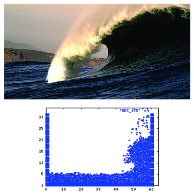
|
| Figure 1: (a) Large breaking wave. (b) PFEM results for a large wave hitting a verticall wall in 2D. |
The layout of the paper is the following. In the next section the basic ideas of the PFEM are outlined. Next the basic equation for an incompressible flow using a Lagrangian description and the FIC formulation are presented. Then a fractional step scheme for the transient solution via standard finite element procedures is described. Details of the treatment of the coupled FSI problem are given. The procedures for mesh generation and for identification of the free surface nodes are briefly outlined. Finally, the efficiency of the particle finite element method (PFEM) is shown in its application to a number of FSI problems involving large flow motions, surface waves, moving bodies. etc.
2 Rationale of the Particle Finite Element Method
Let us consider a domain containing both fluid and solid subdomains. The moving fluid particles interact with the solid boundaries thereby inducing the deformation of the solid which in turn affects the flow motion and, therefore, the problem is fully coupled.
FSI problems traditionally have been solved using an arbitrary Eulerian-Lagrangian description (ALE) for the flow equation whereas the structure is modelled with a full Lagrangian formulation. Many examples of applications of this type of approach are found in the literature. A good review can be found in [Donea and Huerta (2003) [9]; Zienkiewicz and Taylor (2000) [43]].
In the PFEM approach presented here, both the fluid and the solid domains are modelled using an updated Lagrangian formulation. The finite element method (FEM) is used to solve the continuum equations in both domains. Hence a mesh discretizing these domains must be generated in order to solve the governing equations for both the fluid and solid problems in the standard FEM fashion. We note once more that the nodes discretizing the fluid and solid domains can be viewed as material particles which motion is tracked during the transient solution.
The quality of the numerical solution will obviously depend on the discretization chosen as in the standard FEM. Adaptive mesh refinement techniques can be used to improve the solution in zones where large motions of the fluid or the structure occur.
The Lagrangian formulation allows us to track the motion of each single fluid particle (a node). This is useful to model the separation of water particles from the main fluid domain and to follow their subsequent motion as individual particles with an initial velocity and subject to gravity forces.
In summary, a typical solution with the PFEM involves the following steps.
- Discretize the fluid and solid domains with a finite element mesh. The mesh generation process can be based on a standard Delaunay discretization [George (1991) [13]] of the analysis domain using an initial collection of points which then become the mesh nodes. Alternatively, the nodes can be created during the mesh generation process using a front generation method [Irons (1970) [24]; Thompson et al. (1999) [42]].
- Identify the external boundaries for both the fluid and solid domains. This is an essential step as some boundaries (such as the free surface in fluids) may be severely distorted during the solution process including separation and re-entering of nodes. The Alpha Shape method [Edelsbrunner and Mucke (2003) [10]] is used for the boundary definition (see Section 7).
- Solve the coupled Lagrangian equations of motion for the fluid and the solid domains. Compute the relevant state variables in both domains at each time step: velocities, pressure and viscous stresses in the fluid and displacements, stresses and strains in the solid.
- Move the mesh nodes to a new position in terms of the time increment size. This step is typically a consequence of the solution process of step 3.
- Generate a new mesh if needed. The mesh regeneration process can take place after a prescribed number of time steps or when the actual mesh has suffered severe distorsions due to the Lagrangian motion. In our work we use an innovative mesh generation scheme based on the extended Delaunay tesselation (Section 7) [Idelsohn et al. (2003a; 2003b; 2004) [20,21,23]].
- Go back to step 2 and repeat the solution process for the next time step.
Details of the stabilized Lagrangian FEM for the solution of the fluid equations using a FIC formulation are presented in the next section. The fractional step scheme chosen for the transient coupled FSI solution using the FEM and details of the boundary recognition method and the mesh regeneration process are given in subsequent sections. Finally some examples of application of the PFEM are given.
In order to complete this introduction, Figure 2 shows a typical example of a PFEM solution in 2D. The pictures correspond to the analysis of the problem of breakage of a water column described in Section 10.1. Figure 2a shows the initial grid of four node rectangles discretizing the fluid domain and the solid walls. Boundary nodes identified with the Alpha-Shape method have been marked with a circle. Figures 2b and 2c show the mesh for the solution at two later times.
3 Lagrangian Equations for an Incompressible Fluid. FIC Formulation
The standard infinitessimal equations for a viscous incompressible fluid can be written in a Lagrangian frame as [Oñate (1998) [27]; Zienkiewicz and Taylor (2000) [43]]
Momentum
|
|
(1) |
Mass balance
|
|
(2) |
where
|
|
(3) |
|
|
(4) |
Above is the number of space dimensions, is the velocity along the ith global axis (, where is the ith displacement), is the (constant) density of the fluid, are the body forces, are the total stresses given by , is the absolute pressure (defined positive in compression) and are the viscous deviatoric stresses related to the viscosity by the standard expression
|
|
(5) |
where is the Kronecker delta and the strain rates are
|
|
(6) |
In the above all variables are defined at the current time (current configuration).
In our work we will solve a modified set of governing equations derived using a finite calculus (FIC) formulation. The FIC governing equations are [Oñate (1998; 2000; 2004) [27,28,29]; Oñate et al. (2001) [32]]
Momentum
|
|
(7) |
Mass balance
|
|
(8) |
The problem definition is completed with the following boundary conditions
|
|
(9) |
|
|
(10) |
and the initial condition is for . The standard summation convention for repeated indexes is assumed unless otherwise specified.
In Eqs.(7) and (8) and are surface tractions and prescribed velocities on the boundaries and , respectively, are the components of the unit normal vector to the boundary.
The in above equations are characteristic lengths of the domain where balance of momentum and mass is enforced. In Eq.(9) these lengths define the domain where equilibrium of boundary tractions is established. Details of the derivation of Eqs.(7)–(10) can be found in [Oñate (1998; 2000) [27,28]; Oñate et al. (2001) [32]].
Eqs.(7)–(10) are the starting point for deriving stabilized finite element methods to solve the incompressible Navier-Stokes equations in a Lagrangian frame of reference using equal order interpolation for the velocity and pressure variables [Idelsohn et al. (2002; 2003a; 2003b; 2004) [19-21,23]; Oñate et al. (2003) [33]; Aubry et al. (2004) [1]]. Application of the FIC formulation to finite element and meshless analysis of fluid flow problems can be found in [García and Oñate (2003 [12]); Oñate (2000; 2004) [28,29]; Oñate et al. (2000; 2004) [31,34]; Oñate and García (2001) [32]; Oñate and Idelsohn (1998) [30]].
3.1 Transformation of the mass balance equation. Integral governing equations
The underlined term in Eq.(8) can be expressed in terms of the momentum equations. The new expression for the mass balance equation is (see Appendix)
|
|
(11) |
with
|
|
(12) |
The 's in Eq.(11), when scaled by the density, are termed intrinsic time parameters. Similar values for (usually is taken) are used in other works from ad-hoc extensions of the 1D advective-diffusive problem [Codina et al. (1998) [4]; Codina and Blasco (2000) [5]; Codina (2002) [3]; Codina and Zienkiewicz (2002) [6]; Cruchaga and Oñate (1997; 1999) [7,8]; Donea and Huerta (2003) [9]; Franca and Frey (1992) [11]; Hansbo and Szepessy (1990) [15]; Hughes et al. (1986; 1989; 1994) [16-18]; Oñate (1998; 2000; 2004) [27-29]; Sheng et al. (1996) [36]; Storti et al. (1995) [37]; Tezduyar et al. (1992) [41]; Zienkiewicz and Taylor (2000) [43]].
At this stage it is no longer necessary to retain the stabilization terms in the momentum equations. These terms are critical in Eulerian formulations to stabilize the numerical solution for high values of the convective terms. In the Lagrangian formulation the convective terms dissapear from the momentum equations and the FIC terms in these equations are just useful to derive the form of the mass balance equation given by Eq.(11) and can be disregarded there onwards. Consistenly, the stabilization terms are also neglected in the Neuman boundary conditions (eqs.(9)).
The weighted residual expression of the final form of the momentum and mass balance equations can be written as
|
|
(13) |
|
|
(14) |
where and are arbitrary weighting functions equivalent to virtual velocity and virtual pressure fields.
The term in Eq.(14) and the deviatoric stresses and the pressure terms within in Eq.(13) are integrated by parts to give
|
|
(15) |
|
|
(16) |
In Eq.(15) are virtual strain rates. Note that the boundary term resulting from the integration by parts of in Eq.(16) has been neglected as the influence of this term in the numerical solution has been found to be negligible.
3.2 Pressure gradient projection
The computation of the residual terms in Eq.(16) can be simplified if we introduce now the pressure gradient projections , defined as
|
|
(17) |
We express now in Eq.(17) in terms of the which then become additional variables. The system of integral equations is therefore augmented in the necessary number of equations by imposing that the residual vanishes within the analysis domain (in an average sense). This gives the final system of governing equation as:
|
|
(18) |
|
|
(19) |
|
|
(20) |
with . In Eqs.(20) are appropriate weighting functions and the weights are introduced for symmetry reasons.
4 Finite Element Discretization
4.1 Derivation of the discretized equations
We choose continuous interpolations of the velocities, the pressure and the pressure gradient projections over each element with nodes. The interpolations are written as
|
|
(21) |
where denotes nodal variables and are the shape functions [Zienkiewicz and Taylor (2000) [43]]. More details of the mesh discretization process and the choice of shape functions are given in Section 7.
Substituting the approximations (21) into Eqs.(19-20) and choosing a Galerkin form with leads to the following system of discretized equations
|
|
(22a) |
|
|
(22b) |
|
|
(22c) |
where
|
|
(23) |
is the internal nodal force vector derived from the momentum equations, is the deviatoric stress vector, is the strain rate matrix and for 2D problems.
This vector and the rest of the matrices and vectors in Eqs.(22) are assembled from the element contributions given by (for 2D problems)
|
|
(24) |
with and .
As usual the deviatoric stresses are related to the strain rates by Eq.(5)
It can be shown that the system of Eqs.(22) leads to a stabilized numerical solution. For details see [Oñate et al. (2003) [33]].
Remark 1
Eq.(22a) can be written in a more explicit form in terms of the velocity and pressure variables as
|
|
(25) |
where
|
|
(26) |
where is the constitutive matrix. For 2D problems
|
|
(27) |
5 Fractional Step Method for Fluid-Structure Interaction Analysis
A simple and effective iterative algorithm can be obtained by splitting the pressure from the momentum equations as follows
|
|
(28a) |
|
|
(28b) |
In Eq.(28a)
|
|
and is a variable taking values equal to zero or one. For , and for , . Note that in both cases the sum of Eqs.(28a) and (28b) gives the time discretization of the momentum equations with the pressures computed at .
In above equations and in the following superindex denotes an iteration number within each time step.
The value of from Eq.(28b) is substituted now into Eq.(22b) to give
|
|
(29a) |
The product can be approximated by a laplacian matrix, i.e.
|
|
(29b) |
In the above equations and are algorithmic parameters ranging between zero and one. A discussion of the choice of and is given below.
A semi-implicit algorithm can be derived as follows. For each iteration:
Step 1
Compute from Eq.(28a) with where subscript denotes hereonwards a diagonal matrix.
Step 2
Compute and from Eq.(29a) as
|
|
(30a) |
The pressure is computed as follows
|
|
(30b) |
Step 3 Compute from Eq.(28b) with
Step 4 Compute from Eq.(22c) as
|
|
(31) |
Step 5 Solve for the movement of the structure due to the fluid flow forces.
This implies solving the dynamic equations of motion for the structure written as
|
|
(32) |
where and are respectively the displacement and acceleration vectors of the nodes discretizing the structure, and are the mass and stiffness matrices of the structure and is the vector of external nodal forces accounting for the fluid flow forces induced by the pressure and the viscous stresses. Clearly the main driving forces for the motion of the structure is the fluid pressure which acts as normal a surface traction on the structure. Indeed Eq.(32) can be augmented with an appropriate damping term. The form of all the relevant matrices and vectors can be found in standard books on FEM for structural analysis [Zienkiewicz and Taylor (2000) [43]].
Solution of Eq.(32) in time can be performed using implicit or fully explicit time integration algorithms. In both cases the values of the nodal displacements, velocities and accelerations of the structure at are found for the th iteration.
Step 6
Update the mesh nodes in a Lagrangian manner. From the definition of the velocity it is deduced.
|
|
(33) |
Step 7
Generate a new mesh. This can be effectively performed using the procedure described in Section 6.
Step 8
Check the convergence of the velocity and pressure fields in the fluid and the displacements strains and stresses in the structure. If convergence is achieved move to the next time step, otherwise return to step 1 for the next iteration with .
Despite the motion of the nodes within the iterative process, in general there is no need to regenerate the mesh at each iteration. A new mesh is typically generated after a prescribed number of converged time steps, or when the nodal displacements induce significant geometrical distorsions in some elements. In the examples presented in the paper the mesh in the fluid domain has been regenerated at each time step.
The boundary conditions are applied as follows. No condition is applied in the computation of the fractional velocities in Eq.(28a). The prescribed velocities at the boundary are applied when solving for in step 3. The prescribed pressures at the boundary are imposed by making the pressure increments zero at the relevant boundary nodes and making equal to the prescribed pressure values.
Details of the treatment of the contact conditions at the solid-fluid interface are given in Section 8 [Idelsohn et al. (2004) [23]].
Note that solution of steps 1, 3 and 4 does not require the solution of a system of equations as a diagonal form is chosen for and . The whole solution process within a time step can be linearized by choosing and now the iteration loop is no longer necessary. The implicit solution for is however very effective as larger time steps can be used. This requires some iterations within steps 1-8 until converged values for the fluid and solid variables and the new position of the mesh nodes at time are found.
In the examples presented in the paper the time increment size has been chosen as
|
|
(34) |
where is the distance between node and the closest node in the mesh.
Remark 2
Although not explicitely mentioned for all matrices and vectors in Eqs.(28)-(32) are computed at the final configuration . This means that the integration domain changes for each iteration and, hence, all the terms involving space derivatives must be updated at each iteration. This problem dissapears if is taken as the reference configuration () as this remains fixed during the iteration. The penalty to pay in this case, however, is the evaluation of the Jacobian matrix at each iterations [Aubry et al. (2004) [1]].
6 Treatment of Contact Between Fluid and Solid Interfaces
The condition of prescribed velocities or pressures at the solid boundaries in the PFEM are applied in strong form to the boundary nodes. These nodes might belong to fixed external boundaries or to moving boundaries linked to the interacting solids. In some problems it is useful to define a layer of nodes adjacent to the external boundary in the fluid where the condition of prescribed velocity is imposed. These nodes typically remain fixed during the solution process. Contact between water particles and the solid boundaries is accounted for by the incompressibility condition which naturally prevents the penetration of the water nodes into the solid boundaries. This simple way to treat the water-wall contact is another attractive feature of the PFEM formulation.
7 Generation of a New Mesh
One of the key points for the success of the Lagrangian flow formulation described here is the fast regeneration of a mesh at every time step on the basis of the position of the nodes in the space domain. In our work the mesh is generated using the so called extended Delaunay tesselation (EDT) presented in [Idelsohn et al. (2003a; 2003c; 2004) [20,23,24]]. The EDT allows one to generate non standard meshes combining elements of arbitrary polyhedrical shapes (triangles, quadrilaterals and other polygons in 2D and tetrahedra, hexahedra and arbitrary polyhedra in 3D) in a computing time of order , where is the total number of nodes in the mesh (Figure 3). The continuous shape functions of the elements can be simply obtained using the so called meshless finite element interpolation (MFEM). Details of the mesh generation procedure and the derivation of the MFEM shape functions can be found in [Idelsohn et al. (2003a; 2003c; 2004) [20,23,24]].
Once the new mesh has been generated the numerical solution is found at each time step using the fractional step algorithm described in the previous section.
The combination of elements with different geometrical shapes in the same mesh is one of the innovative aspects of the Lagrangian formulation presented here.
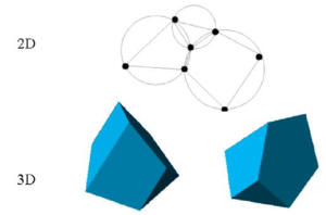
|
| Figure 3: Generation of non standard meshes combining different polygons (in 2D) and polyhedra (in 3D) using the extended Delaunay technique. |
8 Identification of Boundary Surfaces
One of the main tasks in the PFEM is the correct definition of the boundary domain. Sometimes, boundary nodes are explicitly identified differently from internal nodes. In other cases, the total set of nodes is the only information available and the algorithm must recognize the boundary nodes.
The use of the extended Delaunay partition makes it easier to recognize boundary nodes.
Considering that the nodes follow a variable distribution, where is the minimum distance between two nodes, the following criterion has been used. All nodes on an empty sphere with a radius greater than , are considered as boundary nodes. In practice, is a parameter close to, but greater than one. Note that this criterion is coincident with the Alpha Shape concept [Edelsbrunner and Mucke (1999) [10]].
Once a decision has been made concerning which nodes are on the boundaries, the boundary surface must be defined. It is well known that in 3-D problems the surface fitting for a number of nodes is not unique. For instance, four boundary nodes on the same sphere may define two different boundary surfaces, a concave one and a convex one.
In this work, the boundary surface is defined by all the polyhedral surfaces (or polygons in 2D) having all their nodes on the boundary and belonging to just one polyhedron.
Figure 4 shows example of the boundary recognition using the Alpha Shape technique.
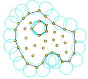
|
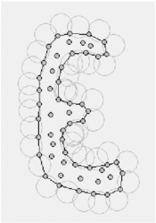
|
| Figure 4: Examples of boundary recognition with the Alpha Shape method. Empty circles with radius greater than define the boundary particles. | |
The correct boundary surface is important to define the normal external to the surface. Furthermore, in weak forms (Galerkin) such as those used here a correct evaluation of the volume domain is also important. In the criterion proposed above, the error in the boundary surface definition is proportional to which is an acceptable error. The only way to obtain a more accurate boundary surface definition is by reducing the distance between the nodes.
The method described also allows one to identify isolated fluid particles outside the main fluid domain. These particles are treated as part of the external boundary where the pressure is fixed to the atmospheric value.
Figure 5 shows a schematic example of the process to identify individual particles (or a group of particles) starting from a given collection of nodes. A practical application of the method for identifying free surface particles is shown in Figure 6. The example corresponds to the analysis of the motion of a fluid within an oscilating ellipsoidal container. Note that the method captures the individual water drops departuring from the free surface during the fluid motion.
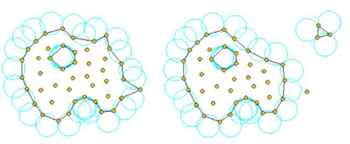
|
| Figure 5: Identification of individual particles (or a group of particles) starting from a given collection of nodes. |
9 Modelling a “Rigid” Structure as a Viscous Fluid
A simple and yet effective way to analyze the rigid motion of solid bodies in fluids with the Lagrangian flow description is to model the solid as a fluid with a viscosity much higher than that of the surrounding fluid. The fractional step scheme of Section 5 can be readily applied skipping now step 5 and solving now for the simultaneous motion of both fluid domains (the actual fluid and the fictitious fluid modelling the quasi-rigid body). Examples of this type are presented in Sections 10.3 and 10.4.
Indeed this approach can be further extended to account for the elastic deformation of the solid treated now as a visco-elastic fluid. This will however introduce some complexity in the formulation and the full coupled FSI scheme described in Section 5 is preferable.
10 Examples
The examples chosen show the applicability of the PFEM to solve problems involving large fluid motions and FSI situations. The fractional step algorithm of Section 5 with and has been used in all cases.
In examples 10.1-10.10 a value of has been chosen. This basically means that the final configuration has been taken as the reference configuration at each iteration. In example 10.11 has been selected and, hence, the initial configuration has been taken as a fixed reference configuration for all the iterations within a time step.
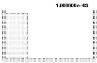
|
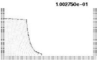
|
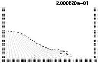
|
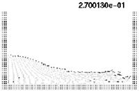
|
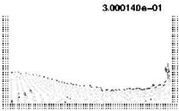
|
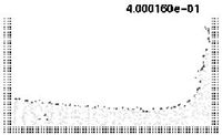
|
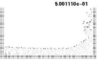
|
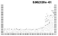
|
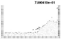
|
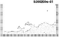
|
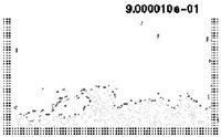
|
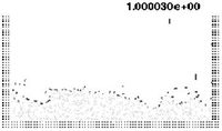
|
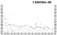
|
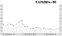
|
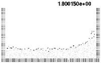
|
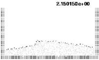
|
| Figure 7: Water column collapse at different time steps. | |
10.1 Collapse of a water column
The first problem solved to show the potential of the PFEM is the study of the collapse of a water column. This problem was solved by Koshizu and Oka (1996) [25] both experimentally and numerically. It has became a classical example to validate the Lagrangian formulation for fluid flows. The water is initially kept within a rectangular container including a removable vertical board. A double layer of nodes in the solid walls is used in order to prevent water nodes from exiting the analysis domain. The boundary conditions impose zero velocity at the wall nodes and zero (atmospheric) pressure at the free surface. Figures 7b and 7c show the mesh discretizing the water domain and the solid walls at two different times of the analysis. Note that the method allows one to follow the large motion of the water particles including separation of some water drops. The collapse starts at time , when the board is removed. Viscosity and surface tension are neglected in the analysis. Figure 7 shows the point positions at different time steps. The dark points represent the free-surface detected with the algorithm described in Section 8. The internal points are shown in a gray colour and the fixed points in black. The meshes generated at different times during the fluid motion are shown in Figure 2.
The water is running on the bottom wall until, at it impinges on the right vertical wall. Breaking waves appear at . At about . the wave again reaches the left wall. Agreement with the experimental results of [Koshizuka and Oka (1996) [25]] both in the shape of the free surface as well as in its time evolution are excellent.
The 3D solution of the same problem is shown in Figure 8. More information on the PFEM solution of this problem can be found in Idelsohn et al. (2004) [23].
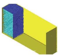
|
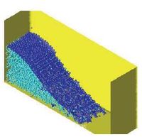
|
| a) | b) |
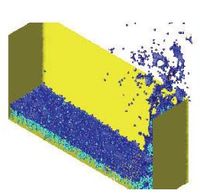
|
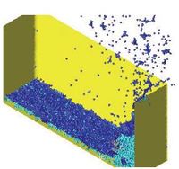
|
| c) | d) |
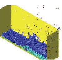
|
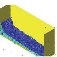
|
| e) | f) |
| Figure 8: Water column collapse in a 3D domain. | |
10.2 Sloshing problems
The simple problem of the free oscillation of an incompressible liquid in a container is considered next. Numerical solutions for this problem can be found in several references [Radovitzki and Ortiz (1998) [35]]. This problem is interesting because there is an analytical solution for small amplitudes. Figure 9 shows a schematic view of the problem and the point distribution in the initial position. The dark points represent the fixed points on the walls where the velocity is fixed to zero.
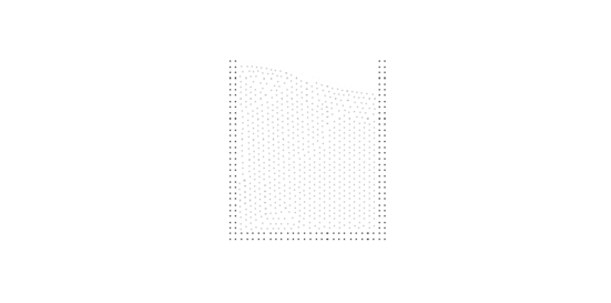
|
| Figure 9: Sloshing. Initial point distribution. |
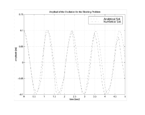
|
| Figure 10: Sloshing: Comparison of the numerical and analytical solutions. |
Figure 10 shows the time evolution of the amplitude compared with the analytical results for the near inviscid case. Little numerical viscosity is observed on the phase wave and amplitude in spite of the relative poor point distribution.
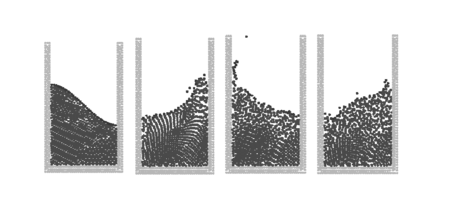
|
| Figure 11: PFEM results for a large amplitude sloshing problems. |
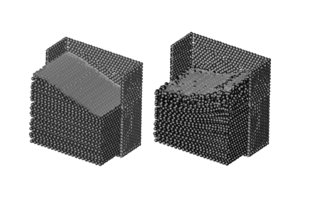
|
| Figure 12: 3D sloshing problem. |
The analytical solution is only acceptable for small wave amplitudes. For larger amplitudes, additional waves are overlapping and, finally, the wave breaks and also some particles separate from the fluid domain due to their large velocity. Figure 11 shows the numerical results obtained with the PFEM for larger sloshing amplitudes. Breaking waves as well as separation effects can be seen on the free-surface. This particular and very complicated effect is well represented by the PFEM.
In order to test the potential of the PFEM in a 3D domain, the same sloshing problem was solved in 3D. Figure 12 show the different point positions at two time steps. Each point position was represented by a sphere and only a half of the fixed recipient is represented on the figure. This sphere representation is only used in order to improve the visualization of the numerical results.
10.3 Wave breaking on a beach
A simulation of the propagation of a water wave and its breaking due to shoaling over a plane slope is presented next. This example was numerically studied in [Radovitzki and Ortiz (1998) [35]] with a Lagrangian formulation using directly the standard Finite Element Method with remeshing. There is also an analytical solution for a simplified approximation that is used for comparisons [Laitone (1960) [26]] where the geometry of the problem as well as a discussion of the analytical solution may be found. Figure 13 shows the initial point distribution and Figure 11 a comparison with the analytical free-surface at different time steps.
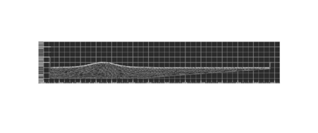
|
| Figure 13: Wave breaking on a beach. Initial geometry and point positions. |
Initially (Figures 14a. and 14b.) the wave travels over a constant depth bottom towards the slope with no ostensible change of shape. Strongly non-linear effects appear when the wave hits the slope (Fig. 14c.). The crest of the wave accelerates until it reaches the shore (Fig. 14d.). At this time the comparisons with the analytical solution are in agreement only in the wave position. The shape of the wave obtained with the numerical solution is totally different. The reason is that before the breaking process the analytical solution gives symmetrical shape waves, which are not physical. Subsequently, a water jet is formed at the crest plunge making the breaking wave (Figs. 14e. and 14f.) and coming in contact with the nearly still surface of the water ahead. In Ref. [Radovitzki and Ortiz (1998) [35]] the computation is stopped before this contact point. Using the methodology proposed in this paper, the analysis may be continued until the end. In Figs. 14g. and 14h. the wave finally hits a lateral wall (introduced in the model to stop the lateral effects) producing drop separations, and then coming back toward to the left as a new wave.
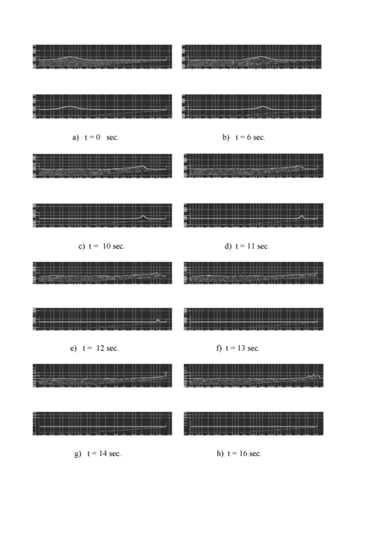
|
| Figure 14: Wave breaking on a beach. Comparison with analytical results at different time steps. Top: PFEM solution. Bottom: Analytical solution. |
The ability of the PFEM to accurately simulate the various stages of the wave breaking is noteworthy.
In order to show the power of the PFEM, the same problem was solved in a 3D domain. Now, the initial position of the wave was given an oblique angle with the beach line. In this way, 3D effects show more clearly. When the wave hits the slope, the crest of the wave accelerates differently accordingly with the depth, inducing the wave to correct its oblique position and break parallel to the beach. The results may be seen in Figure 15 for different time steps.
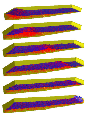
|
| Figure 15: Breaking wave on a beach. Oblique wave on a 3D domain. |
10.4 Fixed ship hit by wave
This example is a very schematic representation of a ship when is hit by a big wave. The ship can not move and initially the free-surface near the ship is horizontal. Fixed nodes represent the ship as well as the domain walls. The example tests the suitability of the PFEM to solve water-wall contact situations even in the presence of curved walls. Note the breaking and splashing of the waves under the ship prow and the rebound of the incoming wave. It is also interesting to see the different water-wall contact situations at the internal and external ship surfaces and the moving free-surface at the back of the ship.

|

|

|

|

|

|

|

|

|

|

|

|

|

|
| Figure 16: Fixed ship hit by incoming wave | |
10.5 Horizontal motion of a rigid ship in a reservoir
In the next example (Figure 17) the same ship of the previous example moves now horizontally at a fixed velocity in a water reservoir. The free-surface, which was initially horizontal, takes the correct position at the ship prow and stern. Again, the complex water-wall contact problem is naturally solved in the curved prow region.

|

|

|

|

|

|

|

|

|

|

|

|

|

|
| Figure 17: Moving ship with fixed velocity | |
10.6 Semi-submerged rotating water mill
The example shown in Figure 18 is the analysis of a rotating water mill semi-submerged in water. The blades of the mill are treated as a rigid body with an imposed rotating velocity, while the water is initially in a stationary flat position. Fluid structure interactions with free-surfaces and water fragmentation are well reproduced in this example.
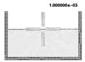
|
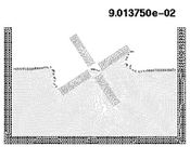
|
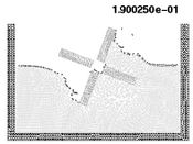
|
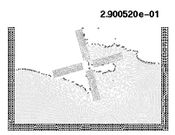
|
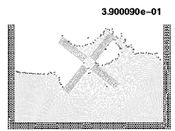
|
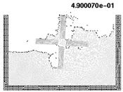
|
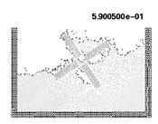
|
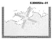
|
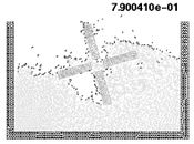
|
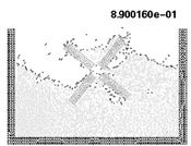
|
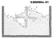
|
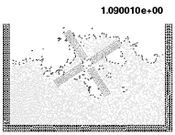
|
| Figure 18: Rotating water mill. | ||
10.7 Floating wood piece
The next example shows an initially stationary recipient with a floating piece of wood where a wave is produced on the left side. The wood has been simulated by a liquid of higher viscosity as described in Section 9. The wave intercepts the wood piece producing a breaking wave and displacing the floating wood as shown in Figure 19.

|
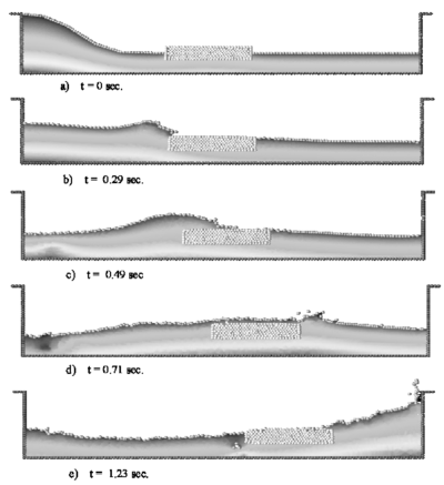
|
| Figure 19: Floating wood piece hit by a wave |
10.8 Ships hit by an incoming wave
In the example of Figure 20 the motion of a fictitious rigid ship hit by an incoming wave is analyzed. The dynamic motion of the ship is induced by the resultant of the pressure and the viscous forces acting on the ship boundaries. The horizontal displacement of the gravity center of the ship was fixed to zero. In this way, the ship moves only vertically although it can freely rotate. The position of the ship boundary at each time step defines a moving boundary condition for the free surface particles in the fluid. Figure 20 shows instants of the motion of the ship and the surrounding fluid. It is interesting to see the breaking of a wave on the ship prow as well as on the stern when the wave goes back. Note that some water drops slip over the ship deck.
Figure 21 shows the analysis of a similar problem using precisely the same approach. The section of the ship analyzed corresponds now to that of a real container ship. Different to the previous case the rigid ship is free to move laterally due to the sea wave forces. The objective of the study was to assess the influence of the stabilizers in the ship roll. The figures show clearly how the PFEM predicts the ship and wave motions in a realistic manner.
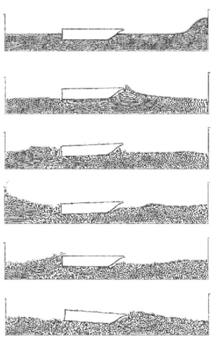
|
| Figure 20: Motion of a rigid ship hit by an incoming wave. The ship is modelled as a rigid solid restrained to move in the vertical direction. |
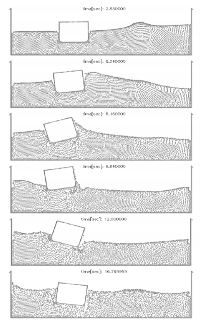
|
| Figure 21: Ship with stabilizers hit by a lateral wave |
10.9 Tank-ship hit by a lateral wave
Figure 22 represents a transversal section of a tank-ship and a wave approaching it. The tank-ship is modelled as a rigid body and it carries a liquid inside which can move freely within the ship domain.
Initially () the ship is released from a fixed position and the equilibrium configuration found is consistent with Archimedes principle. During the following time steps the external wave hits the ship and both the internal and the external fluids interact with the ship boundaries. At times and 8.55 breaking waves and some water drops slipping along the ship deck can be observed. Figure 23 shows the pressure pattern at two time steps.
| time[sec]: 1.950000 |
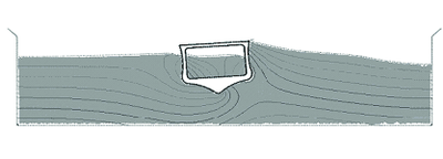
|
| time[sec]: 6.150000 |

|
| Figure 23: Tank ship under lateral wave. Pressure distribution at two time steps |
10.10 Rigid cube falling into a water container
In the next example a solid cube is initially free and falls into a container of water recipient. In this example, the rigid solid is modeled first as a fictitious fluid with a higher viscosity, similarly as for the floating solid of Section 10.7. The results of this analysis are shown in Figure 24. Note that the method reproduces very well the interaction of the cube with the free surface as well as the overall sinking process. A small deformation of the cube is produced. This can be reduced by increasing further the fictitious viscosity of the cube particles.
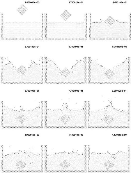
|
| Figure 24: Solid cube falling into a recipient with water. The cube is modelled as a very viscous fluid |
The same problem is analyzed again considering now the cube as a rigid solid subjected to pressure and viscous forces acting in its boundaries. The resultant of the fluid forces and the weight of the cube are applied to the center of the cube. These forces govern the displacement of the cube which is computed by solving the dynamic equations of motion as described in the fractional step algorithm of Section 5, similarly as for the rigid ships of the three previous examples. Here again the moving cube contours define a boundary condition for the fluid particles at each time step.
Initially the solid falls freely due to the gravity forces (Figure 25). Once in contact with the water surface, the Alpha-Shape method recognizes the different boundary contours which are shown with a thick line in the figure. The pressure and viscous forces are evaluated in all the domain and in particular on the cube contours. The fluid forces introduce a negative acceleration in the vertical motion until, once the cube is completely inside the water, the vertical velocity becomes zero. Then, buoyancy forces bring the cube up to the free-surface. It is interesting to observe that there is a rotation of the cube. The reason is that the center of the floating forces is higher in the rotated position than in the initial ones.
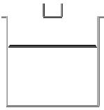
|
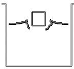
|
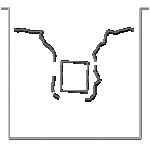
|
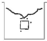
|
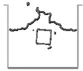
|
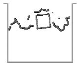
|
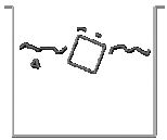
|
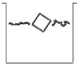
|
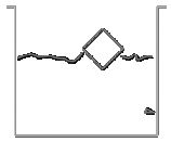
|
| Figure 25: Cube falling into a recipient with water. The cube is modelled as a rigid solid. Motion of the cube and free surface positions at different time steps. | ||
Figure 26 shows a repetition of the same problem showing now all the finite elements in the mesh discretizing the fluid. We recall that in all the problems here described the mesh in the fluid domain is regenerated at each time step combining linear triangles and quadrilateral elements as described in Section 7. Note that some fluid particles separate from the fluid domain. These particles are treated as free boundary points with zero pressure and hence fall due to gravity.
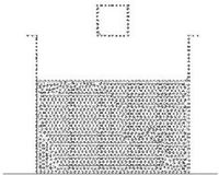
|
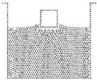
|
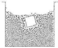
|
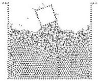
|
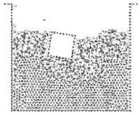
|
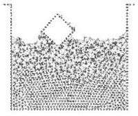
|
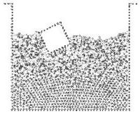
|
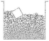
|
| Figure 26: Cube falling in a water recipient. The cube is modeled as a rigid solid. The finite element meshes generated at the selected instants are shown. | |
It is interesting to see that the final position of the cube is different from that of Figure 25. This is due to the unstable character of the cube motion. A small difference in the numerical computations (for instance in the mesh generation process) shifts the movement of the cube towards the right or the left. Note that a final rotated equilibrium position is found in both cases.
10.11 The Rayleigh-Bénard Instability
This example shows that the PFEM can also be successfully used to solve fluid flow problems traditionally analyzed with Eulerian formulations. The problem solved is that of a heated thin cavity containing a fluid. The flow pattern yields the so called Rayleigh-Bénard hydrodynamical instability giving a roll pattern along the cavity. In this case the Lagrangian fluid flow equations are solved together with the heat transfer equation also written in a Lagrangian manner. As mentioned at the introduction of Section 10 a value of has been taken in this example. Details of the solution scheme using a Boussinesq approximatlions for the coupling between the heat transfer equation and the flow equations are given in Aubry et al. (2004) [1].
The bottom and upper part are isothermal with a temperature of for the bottom and for the top. The initial and reference temperature in the fluid is and the side parts are adiabatic. The Rayleigh number is and the Prandtl number is . The mesh has 35500 nodes and 69700 elements at the beginning of the analysis. The numerical computations start with the fluid at rest as the initial conditions. For rigid-rigid boundary conditions, the critical value of the Rayleigh number is 1708 so that the flow is here supercritical. However, a quasi-steady state is reached, with periodic oscillations of the temperature and the cells. Figure 27 shows results of the temperature and velocity field showing the development of rolls. Numerical results have been plotted using the GiD pre/postprocessing system developed at CIMNE [Gid (2004) [14]]. More details on the application of the PFEM to this problem can be found in Aubry et al. (2004) [1].
11 CONCLUSIONS
The particle finite element method (PFEM) seems ideal to treat problems involving fluids with free surface and submerged or floating structures within a unified Lagrangian finite element framework. Problems such as the analysis of fluid-structure interactions, large motion of fluid or solid particles, surface waves, water splashing, separation of water drops, etc. can be easily solved with the PFEM. The success of the method lies in the accurate and efficient solution of the equations of an incompressible fluid and of solid dynamics using a stabilized finite element method via a fractional step scheme allowing the use of low order elements with equal order interpolation for all the variables. Other essential solution ingredients are the efficient regeneration of the finite element mesh using an extended Delaunay tesselation, the meshless finite element interpolation (MFEM) and the identification of the boundary nodes using an Alpha Shape type technique. The examples presented have shown the potential of the PFEM for solving a wide class of practical FSI problems.
Acknowledgements
Thanks are given to Prof. R.L Taylor for many useful suggestions and to Mr. Nestor Calvo for this help in the development of the mesh generation process using the extended Delaunay technique.
Appendix
From Eqs.(7) and (3) it can be obtained (taking into account the definition of the stresses and Eqs.(5))
|
|
(A.1) |
where
|
|
(A.2a) |
and
|
|
(A.2b) |
Substituting Eq.(A.1) into Eq.(8) and retaining the terms involving the derivatives of with respect to only, leads to the following expression for the stabilized mass balance equation
|
|
(A.3) |
with
|
|
(A.4) |
References
[1] Aubry, R., Idelsohn, S.R. and Oñate, E. (2004). Particle finite element method in fluid mechanics including thermal convection-diffusion. Computer & Structures, submitted.
[2] Chorin, A.J. (1967). A numerical solution for solving incompressible viscous flow problems. J. Comp. Phys., 2: 12–26.
[3] Codina, R. (2002). Stabilized finite element approximation of transient incompressible flows using orthogonal subscales. Comput. Methods Appl. Mech. Engrg., 191: 4295–4321..
[4] Codina, R., Vazquez, M. and Zienkiewicz, O.C. (1998). A general algorithm for compressible and incompressible flow - Part III. The semi-implicit form. Int. J. Num. Meth. in Fluids, 27: 13–32.
[5] Codina, R. and Blasco, J. (2000). Stabilized finite element method for the transient Navier-Stokes equations based on a pressure gradient operator. Comput. Methods in Appl. Mech. Engrg., 182: 277–301.
[6] Codina, R. and Zienkiewicz, O.C. (2002). CBS versus GLS stabilization of the incompressible Navier-Stokes equations and the role of the time step as stabilization parameter. Communications in Numerical Methods in Engineering, 18 (2): 99–112.
[7] Cruchaga, M.A. and Oñate, E. (1997). A finite element formulation for incompressible flow problems using a generalized streamline operator. Comput. Methods in Appl. Mech. Engrg., 143: 49–67..
[8] Cruchaga, M.A. and Oñate, E. (1999). A generalized streamline finite element approach for the analysis of incompressible flow problems including moving surfaces. Comput. Methods in Appl. Mech. Engrg., 173: 241–255..
[9] J. Donea and A. Huerta, Finite Element Methods for Flow Problems. Wiley, 2003.
[10] Edelsbrunner, H. and Mucke, E.P. (1999). Three dimensional alpha shapes. ACM Trans. Graphics, 13: 43–72.
[11] Franca, L.P. and Frey, S.L. (1992). Stabilized finite element methods: II. The incompressible Navier-Stokes equations. Comput. Method Appl. Mech. Engrg., 99: 209–233.
[12] García, J. and Oñate, E. (2003). An unstructured finite element solver for ship hydrodynamic problems. in J. Appl. Mech., 70: 18–26, January.
[13] George. (1991). Automatic mesh generation. Application to the finite element method, J. Wiley.
[14] GiD. (2004). The personal pre/postprocessor. CIMNE, Barcelona, www.gidhome.com.
[15] Hansbo, P. and Szepessy, A. (1990). A velocity-pressure streamline diffusion finite element method for the incompressible Navier-Stokes equations. Comput. Methods Appl. Mech. Engrg., 84: 175–192.
[16] Hughes, T.J.R., Franca, L.P. and Balestra, M. (1986). A new finite element formulation for computational fluid dynamics. V Circumventing the Babuska-Brezzi condition: A stable Petrov-Galerkin formulation of the Stokes problem accomodating equal order interpolations. Comput. Methods Appl. Mech. Engrg., 59: 85–89.
[17] Hughes, T.J.R., Franca, L.P. and Hulbert, G.M. (1989). A new finite element formulation for computational fluid dynamics: VIII. The Galerkin/least-squares method for advective-diffusive equations. Comput. Methods Appl. Mech. Engrg., 73: 173–189.
[18] Hughes, T.J.R., Hauke, G. and Jansen, K. (1994). Stabilized finite element methods in fluids: Inspirations, origins, status and recent developments. in: Recent Developments in Finite Element Analysis. A Book Dedicated to Robert L. Taylor, T.J.R. Hughes, E. Oñate and O.C. Zienkiewicz (Eds.), CIMNE, Barcelona, Spain, pp. 272–292.
[19] Idelsohn, S.R., Oñate, E., Del Pin F. and Calvo, N. (2002). Lagrangian formulation: the only way to solve some free-surface fluid mechanics problems. Fith World Congress on Computational Mechanics, Mang HA, Rammerstorfer FG and Eberhardsteiner J. (eds), July 7–12, Viena, Austria.
[20] Idelsohn, S.R., Oñate, E., Calvo, N. and del Pin, F. (2003a). The meshless finite element method. Int. J. Num. Meth. Engng., 58,6: 893–912.
[21] Idelsohn, S.R., Oñate, E. and Del Pin, F. (2003b). A lagrangian meshless finite element method applied to fluid-structure interaction problems. in Computer and Structures, 81: 655–671.
[22] Idelsohn, S.R., Calvo, N. and Oñate, E. (2003c). Polyhedrization of an arbitrary point set. Comput. Method Appl. Mech. Engng., 192 (22-24): 2649–2668.
[23] Idelsohn, S.R., Oñate, E. and Del Pin, F. (2004). The particle finite element method a powerful tool to solve incompressible flows with free-surfaces and breaking waves. Int. J. Num. Meth. Engng., submitted.
[24] Irons, B.M. (1970). A frontal solution program. Int. J. Num. Meth. Engng., 2: 5–32.
[25] Koshizuka, S. and Oka, Y. (1996). Moving particle semi-implicit method for fragmentation of incompressible fluid. Nuclear Engng. Science, 123: 421–434.
[26] Laitone, E.V. (1960). The second approximation to cnoidal waves. J. Fluids Mech., 9: 430.
[27] Oñate, E. (1998). Derivation of stabilized equations for advective-diffusive transport and fluid flow problems. Comput. Meth. Appl. Mech. Engng., 151: 233–267.
[28] Oñate, E. (2000). A stabilized finite element method for incompressible viscous flows using a finite increment calculus formulation. Comp. Meth. Appl. Mech. Engng., 182 (1–2): 355–370.
[29] Oñate, E. (2004). Possibilities of finite calculus in computational mechanics. Int. J. Num. Meth. Engng., 60 (1): 255–281.
[30] Oñate, E. and Idelsohn, S.R. (1998). A mesh free finite point method for advective-diffusive transport and fluid flow problems. Computational Mechanics, 21: 283–292.
[31] Oñate, E., Sacco, C. and Idelsohn, S.R. (2000). A finite point method for incompressible flow problems. Comput. and Visual. in Science, 2: 67–75.
[32] Oñate, E. and García, J. (2001). A finite element method for fluid-structure interaction with surface waves using a finite calculus formulation. Comput. Meth. Appl. Mech. Engrg., 191: 635–660.
[33] Oñate, E., Idelsohn, S.R. and Del Pin, F. (2003). Lagrangian formulation for incompressible fluids using finite calculus and the finite element method. in Numerical Methods for Scientific Computing Variational Problems and Applications, Y. Kuznetsov, P. Neittanmaki and O. Pironneau (Eds.), CIMNE, Barcelona.
[34] Oñate, E., García, J. and Idelsohn, S.R. (2004). Ship hydrodynamics. In Encyclopedia of Computational Mechanics, E. Stein, R. de Borst and T.J.R. Hughes (Eds), J. Wiley.
[35] Radovitzki, R. and Ortiz, M. (1998). Lagrangian finite element analysis of a Newtonian flows. Int. J. Num. Meth. Engng., 43: 607–619.
[36] Sheng, C., Taylor, L.K. and Whitfield, D.L. (1996). Implicit lower-upper/approximate-factorization schemes for incompressible flows Journal of Computational Physics, 128 (1), 32–42, 1996
[37] Storti, M., Nigro, N. and Idelsohn, S.R. (1995). Steady state incompressible flows using explicit schemes with an optimal local preconditioning. Computer Methods in Applied Mechanics and Engineering, 124: 231–252.
[38] Tezduyar, T.E., Behr, M. and Liou, J. (1992a). A New Strategy for Finite Element Computations Involving Moving Boundaries and Interfaces - The Deforming-Spatial-Domain/Space-Time Procedure: I. The Concept and the Preliminary Numerical Tests. Computer Methods in Applied Mechanics and Engineering, 94, 339–351.
[39] Tezduyar, T.E., Behr, M., Mittal, S. and J. Liou (1992b). A New Strategy for Finite Element Computations Involving Moving Boundaries and Interfaces - The Deforming-Spatial-Domain/Space-Time Procedure: II. Computation of Free-surface Flows, Two-liquid Flows, and Flows with Drifting Cylinders. Computer Methods in Applied Mechanics and Engineering, 94, 353–371..
[40] Tezduyar, T. (2001). Finite Element Interface-Tracking and Interface-Capturing Techniques for Flows with Moving Boundaries and Interfaces ASME Paper IMECE2001/HTD-24206, Proceedings of the ASME Symposium on Fluid-Physics and Heat Transfer for Macro- and Micro-Scale Gas-Liquid and Phase-Change Flows, ASME, New York, New York, CD-ROM.
[41] Tezduyar, T.E., Mittal, S., Ray, S.E. and Shih, R. (1992). Incompressible flow computations with stabilized bilinear and linear equal order interpolation velocity–pressure elements. Comput. Methods Appl. Mech. Engrg., 95: 221–242.
[42] Thompson, J.F., Soni, B.K. and Weatherill, N.P. (Eds.) (1999). Handbook of Grid Generation, CRC Press.
[43] Zienkiewicz, O.C. and Taylor, R.L. (2000). The finite element method. 5th Edition, 3 Volumes, Butterworth–Heinemann.
Document information
Published on 01/01/2004
DOI: 10.1142/S0219876204000204
Licence: CC BY-NC-SA license
Share this document
claim authorship
Are you one of the authors of this document?
