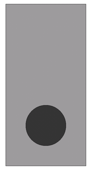
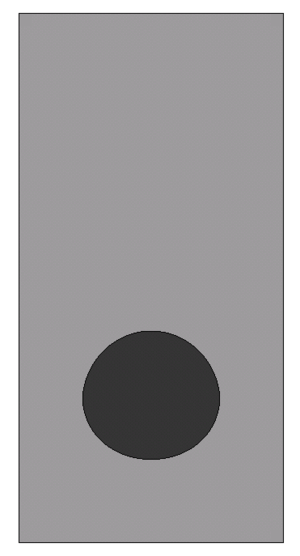
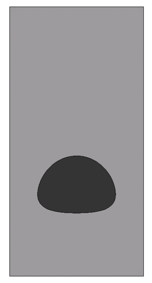
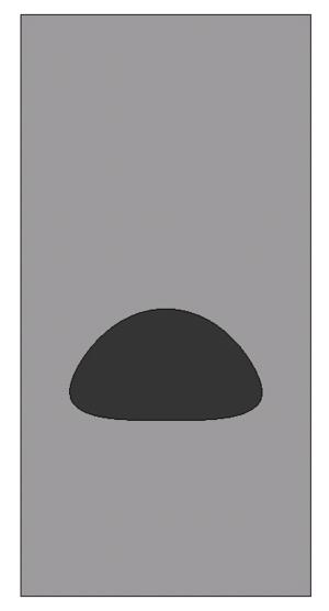
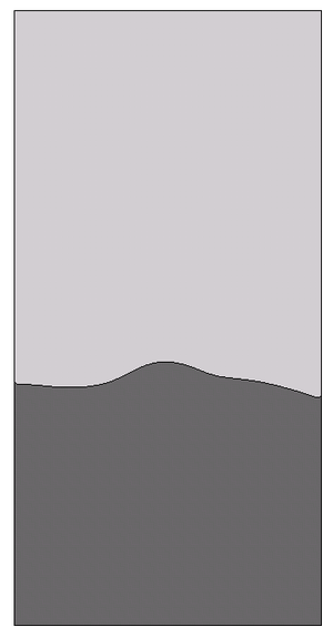
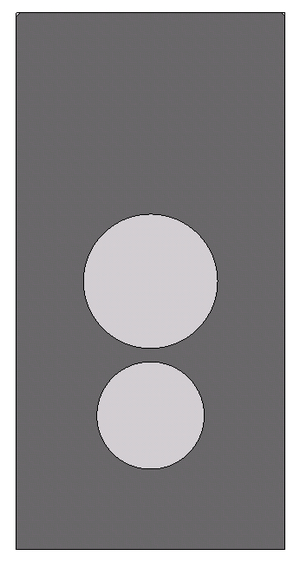
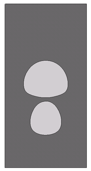
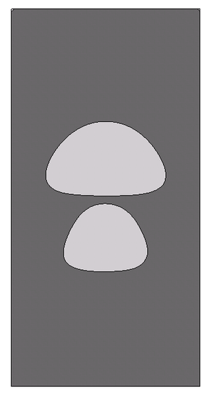
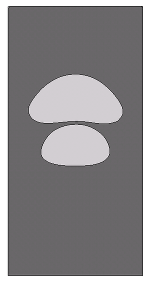
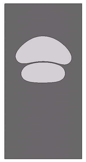
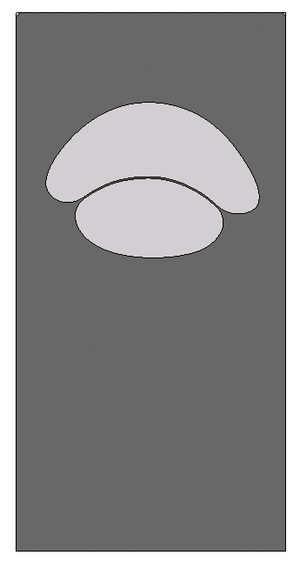
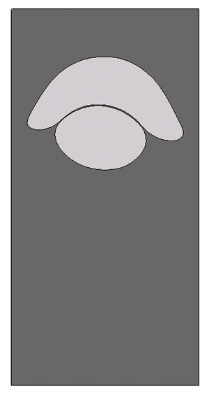
(Created page with "==1 Title, abstract and keywords<!-- Your document should start with a concise and informative title. Titles are often used in information-retrieval systems. Avoid abbreviatio...") |
m (Cinmemj moved page Draft Samper 976567426 to Mier-Torrecilla et al 2010b) |
||
| (One intermediate revision by the same user not shown) | |||
| Line 1: | Line 1: | ||
| − | == | + | ==Abstract== |
| − | + | In this work we extend the Particle Finite Element Method (PFEM) to multi-fluid flow problems with the aim of exploiting the fact that Lagrangian methods are specially well suited for tracking interfaces. We develop a numerical scheme able to deal with large jumps in the physical properties, included surface tension, and able to accurately represent all types of discontinuities in the flow variables. The scheme is based on decoupling the velocity and pressure variables through a pressure segregation method which takes into account the interface conditions. The interface is defined to be aligned with the moving mesh, so that it remains sharp along time, and pressure degrees of freedom are duplicated at the interface nodes to represent the discontinuity of this variable due to surface tension and variable viscosity. Furthermore, the mesh is refined in the vicinity of the interface to improve the accuracy and the efficiency of the computations. | |
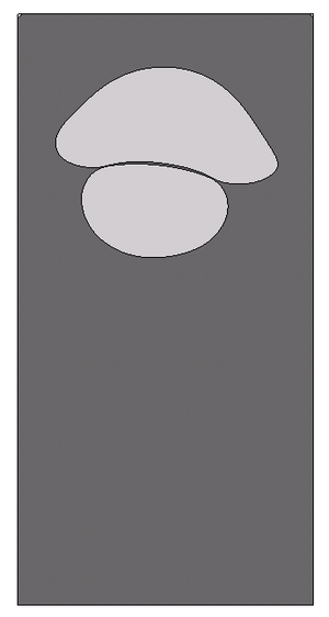
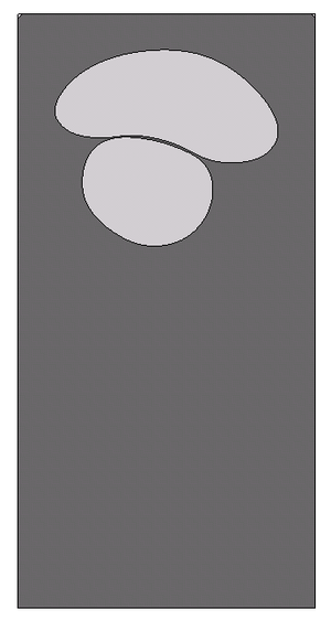
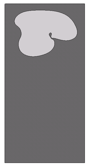
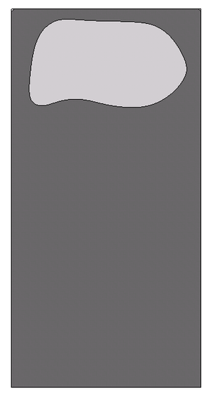
| − | + | We apply the resulting scheme to the benchmark problem of a two-dimensional bubble rising in a liquid column presented in <span id='citeF-1'></span>[[#cite-1|[1]]], and propose two breakup and coalescence problems to assess the ability of a multi-fluid code to model topology changes. | |
| + | Keywords: Particle Finite Element Method (PFEM); Lagrangian simulation; multi-fluid flows; pressure segregation; surface tension; bubble dynamics. | ||
| + | ==1 INTRODUCTION== | ||
| + | The simultaneous presence of multiple fluids with different properties in external or internal flows is found in daily life, environmental problems, and numerous industrial processes. Examples are fluid-fuel interaction in enhanced oil recovery, blending of polymers, emulsions in food manufacturing, rain droplet formation in clouds, fuel injection in engines, and bubble column reactors, to name only a few. Although multi-fluid flows occur frequently in nature and engineering practice, they still pose a major research challenge from both theoretical and computational points of view. | ||
| − | + | In the case of immiscible fluids, the dynamics of the interface between fluids plays a dominant role. The success of the simulation of such flows depends on the ability of the numerical method to model accurately the interface and the phenomena taking place on it, such as the surface tension. The origin of the surface tension force lies in the different intermolecular attractive forces that act in the two fluids, and the result is an interfacial energy per area that acts to resist the creation of new interface, so that the interface behaves like a stretched membrane trying to minimize its area. | |
| − | + | The main difference between a single-fluid flow (homogeneous) and a multi-fluid (heterogeneous) one is the presence of internal interfaces. In addition to the well-known difficulties in the simulation of homogeneous flows, namely the coupling of pressure and velocity through the incompressibility constraint, the need of the discretization spaces to satisfy the inf-sup condition, and the non-linearity of the governing equations, numerical methods for heterogeneous flows face the following challenges: | |
| + | <ol> | ||
| − | + | <li>Accurate definition of the interface position. | |
| − | + | The interface separating the fluids needs to be tracked accurately without introducing excessive numerical smoothing. </li> | |
| + | <li>Modeling the jumps in the fluid properties across the interface. | ||
| + | Large jumps of fluid density and viscosity across the interface need to be properly taken into account in order to satisfy the momentum balance at the vicinity of the interface. </li> | ||
| + | <li>Modeling the discontinuities of the flow variables across the interface. | ||
| − | + | Velocity and pressure may be discontinuous across the interface under certain conditions. </li> | |
| + | <li>Modeling the surface tension. | ||
| − | + | Since surface tension plays a very important role in the immiscible interface dynamics, this force needs to be accurately evaluated and incorporated into the model. </li> | |
| − | + | </ol> | |
| − | + | This paper extends the work of the authors in the study of multi-fluid flows with the Particle Finite Element Method <span id='citeF-2'></span>[[#cite-2|[2]]]. The new contributions include the scheme for describing the interface, the computation of surface tension and the enhanced pressure segregation approach. We have found that these developments are essential for accurately modeling of bubble dynamics. The paper is organized as follows: In Section [[#2 GOVERNING EQUATIONS|2]] we present the governing equations together with the interface conditions and the possible discontinuities of the flow variables. In Section [[#3 INTERFACE DESCRIPTION|3]] we briefly review the interface descriptions most used in the literature, to focus later in the Particle Finite Element Method (Section [[#4 PARTICLE FINITE ELEMENT METHOD|4]]) and the numerical scheme we have developed (Sections [[#5 PRESSURE SEGREGATION FOR THE MULTI-FLUID EQUATIONS|5]] and [[#6 SURFACE TENSION|6]]). Finally, in Section [[#7 NUMERICAL EXAMPLE: RISING BUBBLE|7]] we apply the PFEM to the solution of the two-dimensional bubble rise, breakup and coalescence problems. | |
| − | + | ==2 GOVERNING EQUATIONS== | |
| − | + | <div id='img-1'></div> | |
| + | {| class="floating_imageSCP" style="text-align: center; border: 1px solid #BBB; margin: 1em auto; width: 100%;max-width: 100%;" | ||
| + | |- | ||
| + | |[[Image:draft_Samper_466629376-NSdomain.png|180px|Two-fluid flow configuration.]] | ||
| + | |- style="text-align: center; font-size: 75%;" | ||
| + | | colspan="1" | '''Figure 1:''' Two-fluid flow configuration. | ||
| + | |} | ||
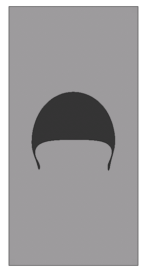
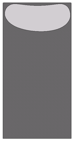
| + | Let <math display="inline">\Omega \subset \boldsymbol{R}^d</math>, <math display="inline">d\in \{ 2,3\} </math>, be a bounded domain containing two different fluids (see Figure [[#img-1|1]]). We denote time by <math display="inline">t</math>, the Cartesian spatial coordinates by <math display="inline">\boldsymbol{x}=\{ x_i\} _{i=1}^d</math>, and the vectorial operator of spatial derivatives by <math display="inline">\boldsymbol{\nabla }=\{ \partial _{x_i}\} _{i=1}^d</math>. The evolution of the velocity <math display="inline">u=u(\boldsymbol{x},t)</math> and the pressure <math display="inline">p=p(\boldsymbol{x},t)</math> is governed by the Navier-Stokes equations: | ||
| − | + | <span id="eq-1.a"></span> | |
| + | <span id="eq-1.b"></span> | ||
| + | <span id="eq-1.c"></span> | ||
| + | {| class="formulaSCP" style="width: 100%; text-align: left;" | ||
| + | |- | ||
| + | | | ||
| + | {| style="text-align: left; margin:auto;width: 100%;" | ||
| + | |- | ||
| + | | style="text-align: center;" | <math>\rho \displaystyle \frac{{d} u}{{d} t}=\boldsymbol{\nabla }\cdot{\boldsymbol{\sigma }}+\rho \boldsymbol{g}\quad \mbox{ in} \;\Omega \times (0,T) </math> | ||
| + | | style="width: 5px;text-align: right;white-space: nowrap;" | (1.a) | ||
| + | |- | ||
| + | | style="text-align: center;" | <math> \displaystyle \frac{{d} \rho }{{d} t}+\rho \boldsymbol{\nabla }\cdot{u}=0 \quad \mbox{ in} \;\Omega \times (0,T) </math> | ||
| + | | style="width: 5px;text-align: right;white-space: nowrap;" | (1.b) | ||
| + | |} | ||
| + | |} | ||
| − | + | where <math display="inline">\rho </math> is the density, <math display="inline">\boldsymbol{\sigma }</math> the Cauchy stress tensor, <math display="inline">\boldsymbol{g}</math> the vector of gravity acceleration, and <math display="inline">\displaystyle \frac{{d} \phi }{{d} t}</math> represents the total or material derivative of a function <math display="inline">\phi </math>. The constitutive equation for a Newtonian and isotropic fluid takes the form | |
| − | + | <span id="eq-2"></span> | |
| + | {| class="formulaSCP" style="width: 100%; text-align: left;" | ||
| + | |- | ||
| + | | | ||
| + | {| style="text-align: left; margin:auto;width: 100%;" | ||
| + | |- | ||
| + | | style="text-align: center;" | <math>\boldsymbol{\sigma }=-p\boldsymbol{I}+2\mu (\boldsymbol{D}-\frac{1}{3}\varepsilon _V\boldsymbol{I}) </math> | ||
| + | |} | ||
| + | | style="width: 5px;text-align: right;white-space: nowrap;" | (2) | ||
| + | |} | ||
| − | + | with <math display="inline">\boldsymbol{I}</math> the identity tensor, <math display="inline">\mu </math> the dynamic viscosity, <math display="inline">\boldsymbol{D}=\frac{1}{2}(\boldsymbol{\nabla }u+\boldsymbol{\nabla }^Tu)</math> the strain rate tensor, and <math display="inline">\varepsilon _V=\boldsymbol{\nabla }\cdot{u}</math> the volumetric strain rate. | |
| − | + | Let <math display="inline">\Gamma _{int}(t)</math> be the interface that cuts the domain <math display="inline">\Omega </math> in two open subdomains, <math display="inline">\Omega{^+}(t)</math> and <math display="inline">\Omega{^-}(t)</math>, which satisfy: <math display="inline">\Omega{^+}\cap \Omega{^-}=\emptyset </math>, <math display="inline">\Omega =\bar \Omega{^+}\cup \bar \Omega{^-}</math>, and <math display="inline">\Gamma _{int}=\bar \Omega{^+}\cap \bar \Omega{^-}=\partial \Omega{^+}\cap \partial \Omega{^-}</math>. In each subdomain, the physical properties are defined as: | |
| − | + | <span id="eq-3"></span> | |
| + | {| class="formulaSCP" style="width: 100%; text-align: left;" | ||
| + | |- | ||
| + | | | ||
| + | {| style="text-align: left; margin:auto;width: 100%;" | ||
| + | |- | ||
| + | | style="text-align: center;" | <math>\rho =\rho (\boldsymbol{x},t)=\left\{ \begin{array}{ll}\rho{^+} & \mbox{ if } \boldsymbol{x}\in \Omega{^+}(t) \\ \rho{^-} & \mbox{ if } \boldsymbol{x}\in \Omega{^-}(t) \end{array} \right., \qquad \mu =\mu (\boldsymbol{x},t)=\left\{ \begin{array}{ll}\mu{^+} & \mbox{ if } \boldsymbol{x}\in \Omega{^+}(t) \\ \mu{^-} & \mbox{ if } \boldsymbol{x}\in \Omega{^-}(t) \end{array} \right. </math> | ||
| + | |} | ||
| + | | style="width: 5px;text-align: right;white-space: nowrap;" | (3) | ||
| + | |} | ||
| − | + | If density and viscosity are assumed to remain constant in each fluid (i.e. fluids are incompressible, immiscible, and isothermal), we have that <math display="inline">\displaystyle \frac{{d} \rho }{{d} t}=0</math> and <math display="inline">\displaystyle \frac{{d} \mu }{{d} t}=0</math>. Consequently, we have on the one side that <math display="inline">\varepsilon _V=\boldsymbol{\nabla }\cdot{u}=0</math>, this is the mass conservation equation for incompressible flows; and on the other side, that <math display="inline">\displaystyle \frac{{d} }{{d} t}\,\Gamma _{int}=0</math>. This latter consequence means that interfaces are material surfaces, which move with the fluid velocity <math display="inline">u</math>, and therefore, they are naturally tracked in Lagrangian formulations. | |
| − | + | ===Boundary and interface conditions=== | |
| − | + | In order for the Navier-Stokes problem ([[#eq-1.c|1]]) to be well-posed, suitable boundary conditions need to be specified. On the external boundary <math display="inline">\partial \Omega =\Gamma _D\cup \Gamma _N</math>, such that <math display="inline">\Gamma _D\cap \Gamma _N=\emptyset </math>, we consider the following: | |
| − | + | <span id="eq-4"></span> | |
| + | <span id="eq-5"></span> | ||
| + | {| class="formulaSCP" style="width: 100%; text-align: left;" | ||
| + | |- | ||
| + | | | ||
| + | {| style="text-align: left; margin:auto;width: 100%;" | ||
| + | |- | ||
| + | | style="text-align: center;" | <math>u=\bar u \quad \mbox{ on} \;\Gamma _D </math> | ||
| + | | style="width: 5px;text-align: right;white-space: nowrap;" | (4) | ||
| + | |- | ||
| + | | style="text-align: center;" | <math> \boldsymbol{\sigma }\cdot \boldsymbol{n}=\bar \boldsymbol{\sigma }_n \quad \mbox{ on} \;\Gamma _N </math> | ||
| + | | style="width: 5px;text-align: right;white-space: nowrap;" | (5) | ||
| + | |} | ||
| + | |} | ||
| − | + | <math display="inline">\bar u</math> is the prescribed velocity, <math display="inline">\boldsymbol{n}</math> the outer unit normal to <math display="inline">\Gamma _N</math>, and <math display="inline">\bar \boldsymbol{\sigma }_n</math> the prescribed traction vector. A Neumann boundary <math display="inline">\Gamma _N</math> with <math display="inline">\bar \boldsymbol{\sigma }_n=\boldsymbol{0}</math> is called ''free surface''. | |
| − | + | On the internal interfaces <math display="inline">\Gamma _{int}</math>, the coupling conditions are <span id='citeF-3'></span>[[#cite-3|[3]]]: | |
| + | <span id="eq-6"></span> | ||
| + | <span id="eq-7"></span> | ||
| + | {| class="formulaSCP" style="width: 100%; text-align: left;" | ||
| + | |- | ||
| + | | | ||
| + | {| style="text-align: left; margin:auto;width: 100%;" | ||
| + | |- | ||
| + | | style="text-align: center;" | <math>\mbox{⟦}u\mbox{⟧}=\boldsymbol{0} \qquad \mbox{ on} \;\Gamma _{int} </math> | ||
| + | | style="width: 5px;text-align: right;white-space: nowrap;" | (6) | ||
| + | |- | ||
| + | | style="text-align: center;" | <math> \mbox{⟦}\boldsymbol{\sigma }\mbox{⟧}\cdot \boldsymbol{n}=\gamma \kappa \boldsymbol{n} \qquad \mbox{ on} \;\Gamma _{int} </math> | ||
| + | | style="width: 5px;text-align: right;white-space: nowrap;" | (7) | ||
| + | |} | ||
| + | |} | ||
| − | + | with <math display="inline">\boldsymbol{n}</math> now the unit normal to <math display="inline">\Gamma _{int}</math>, <math display="inline">\gamma </math> the surface tension coefficient, <math display="inline">\kappa </math> the interface curvature, and <math display="inline">\mbox{⟦}\phi \mbox{⟧}= \phi{^+}-\phi{^-}</math> represents the jump of a quantity <math display="inline">\phi </math> across the interface. | |
| − | + | Equation ([[#eq-6|6]]) expresses the continuity of all velocity components. The normal component has to be continuous when there is no mass flow through the interface, and the tangential components have to be continuous when both fluids are viscous (<math display="inline">\mu ^+,\mu ^->0</math>), similar to a no-slip condition. | |
| + | Equation ([[#eq-7|7]]) expresses that the jump in the normal stresses is balanced with the surface tension force. This force is proportional to the interface curvature and points to the center of the osculating circle that approximates <math display="inline">\Gamma _{int}</math>. The surface tension coefficient <math display="inline">\gamma </math> is assumed constant and its value depends on the two fluids at the interface. | ||
| + | ===2.1 Interface discontinuities=== | ||
| + | Discontinuities at the interface can be of two types: | ||
| − | + | * ''<math>{\cal C}^0</math> discontinuity'', when the flow variable has a kink (i.e. the gradient has a jump), and | |
| − | + | * ''<math>{\cal C}^{-1}</math> discontinuity'', when the flow variable itself has a jump. | |
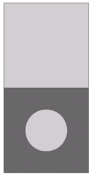
| − | + | Differences in density at the interface cause a kink in the hydrostatic pressure profile, leading to a jump in the pressure gradient, and then to a <math display="inline">{\cal C}^0</math> discontinuity in the pressure field (Fig. [[#img-2|2]]a). | |
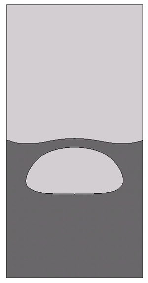
| + | Differences in viscosity lead to discontinuous components of the strain rate tensor <math display="inline">\boldsymbol{D}</math>, and therefore to a <math display="inline">{\cal C}^0</math> discontinuity of the velocity field at the interface (Fig. [[#img-2|2]]b): | ||
| + | <span id="eq-8"></span> | ||
| + | {| class="formulaSCP" style="width: 100%; text-align: left;" | ||
| + | |- | ||
| + | | | ||
| + | {| style="text-align: left; margin:auto;width: 100%;" | ||
| + | |- | ||
| + | | style="text-align: center;" | <math>\boldsymbol{t}\cdot \mbox{⟦}\boldsymbol{\sigma }\mbox{⟧}\cdot \boldsymbol{n}=0 \quad \Longrightarrow \quad \mu ^+\left(\displaystyle \frac{\partial u_t}{\partial n}+\displaystyle \frac{\partial u_n}{\partial s} \right)^+ - \mu ^-\left(\displaystyle \frac{\partial u_t}{\partial n}+\displaystyle \frac{\partial u_n}{\partial s} \right)^- =0 </math> | ||
| + | |} | ||
| + | | style="width: 5px;text-align: right;white-space: nowrap;" | (8) | ||
| + | |} | ||
| + | with <math display="inline">\partial _s = \boldsymbol{t}\cdot \boldsymbol{\nabla }</math> the tangential derivative. | ||
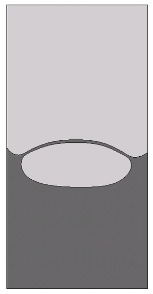
| − | + | Both differences in viscosity and the presence of surface tension cause a <math display="inline">{\cal C}^{-1}</math> discontinuity in the pressure field (Figs. [[#img-2|2]]b and [[#img-2|2]]c), as shown in <span id='citeF-4'></span>[[#cite-4|[4]]]: | |
| + | <span id="eq-9"></span> | ||
| + | {| class="formulaSCP" style="width: 100%; text-align: left;" | ||
| + | |- | ||
| + | | | ||
| + | {| style="text-align: left; margin:auto;width: 100%;" | ||
| + | |- | ||
| + | | style="text-align: center;" | <math>\boldsymbol{n}\cdot \mbox{⟦}\boldsymbol{\sigma }\mbox{⟧}\cdot \boldsymbol{n}=\gamma \kappa \quad \Longrightarrow \quad p^+-p^-=2(\mu ^+-\mu ^-)\displaystyle \frac{\partial u_n}{\partial n}-\gamma \kappa </math> | ||
| + | |} | ||
| + | | style="width: 5px;text-align: right;white-space: nowrap;" | (9) | ||
| + | |} | ||
| + | Notice that even in the case of <math display="inline">\gamma=0</math>, pressure is discontinuous when <math display="inline">\mu ^+\neq \mu ^-</math>. | ||
| + | <div id='img-2a'></div> | ||
| + | <div id='img-2b'></div> | ||
| + | <div id='img-2c'></div> | ||
| + | <div id='img-2'></div> | ||
| + | {| class="floating_imageSCP" style="text-align: center; border: 1px solid #BBB; margin: 1em auto; width: 100%;max-width: 100%;" | ||
| + | |- | ||
| + | |[[Image:draft_Samper_466629376-discontinuities_density.png|372px|(a)]] | ||
| + | |[[Image:draft_Samper_466629376-discontinuities_viscosity.png|372px|(b)]] | ||
| + | |- style="text-align: center; font-size: 75%;" | ||
| + | | (a) | ||
| + | | (b) | ||
| + | |- | ||
| + | | colspan="2"|[[Image:draft_Samper_466629376-discontinuities_surfacetension.png|372px|(c)]] | ||
| + | |- style="text-align: center; font-size: 75%;" | ||
| + | | colspan="2" | (c) | ||
| + | |- style="text-align: center; font-size: 75%;" | ||
| + | | colspan="2" | '''Figure 2:''' Flow discontinuities for: (a) density jump, (b) viscosity jump, and (c) surface tension. | ||
| + | |} | ||
| − | == | + | ==3 INTERFACE DESCRIPTION== |
| − | + | A major challenge in the simulation of interfaces between different fluids is the accurate description of the interface evolution. The location of the interface is in general unknown and coupled to the local flow field which transports the interface. It is essential that the interface remains sharp along time and is able to fold, break and merge. In the past decades a number of techniques have been developed to model interfaces in multi-fluid flow problems, each technique with its own particular advantages and disadvantages. Comprehensive reviews can be found in e.g. <span id='citeF-5'></span><span id='citeF-6'></span><span id='citeF-7'></span><span id='citeF-8'></span>[[#cite-5|[5,6,7,8]]]. <div id='img-3a'></div> | |
| + | <div id='img-3b'></div> | ||
| + | <div id='img-3'></div> | ||
| + | {| class="floating_imageSCP" style="text-align: center; border: 1px solid #BBB; margin: 1em auto; width: 100%;max-width: 100%;" | ||
| + | |- | ||
| + | |[[Image:draft_Samper_466629376-interfacemethods_moving.png|180px|(a)]] | ||
| + | |[[Image:draft_Samper_466629376-interfacemethods_fixed.png|180px|(b)]] | ||
| + | |- style="text-align: center; font-size: 75%;" | ||
| + | | (a) | ||
| + | | (b) | ||
| + | |- style="text-align: center; font-size: 75%;" | ||
| + | | colspan="2" | '''Figure 3:''' (a) Moving mesh adapted to the interface, and (b) fixed mesh, where interface moves through the elements. | ||
| + | |} | ||
| − | [3] | + | The main classification of interface descriptions is regarding the reference frame adopted (see Figure [[#img-3|3]]). In the ''moving mesh methods'', the mesh is deformable and adapted to the interface, which is explicitly tracked along the trajectories of the fluid particles. Examples are methods based on the Arbitrary Lagrangian-Eulerian (ALE) formulation <span id='citeF-9'></span><span id='citeF-10'></span>[[#cite-9|[9,10]]], the deformable-spatial-domain/stabilized space-time deformation (DSD/SST) method <span id='citeF-11'></span><span id='citeF-12'></span>[[#cite-11|[11,12]]], or the fully Lagrangian formulation such as in <span id='citeF-13'></span><span id='citeF-14'></span>[[#cite-13|[13,14]]] and the Particle Finite Element Method <span id='citeF-15'></span><span id='citeF-16'></span><span id='citeF-17'></span><span id='citeF-18'></span>[[#cite-15|[15,16,17,18]]]. |
| − | [ | + | On the other hand, ''fixed mesh methods'' use a separate procedure to describe the position of the interface. They can be further grouped in ''front-tracking methods'', which use massless marker points to follow the fluid interface while the Navier-Stokes equations are solved on a fixed mesh <span id='citeF-19'></span><span id='citeF-20'></span>[[#cite-19|[19,20]]], and ''front-capturing methods'', which introduce a new variable <math display="inline">\psi </math> in the model to describe the presence or not of a fluid in a position of the domain. The most extended front-capturing methods are the Volume-Of-Fluid, originally developed by Hirt <span id='citeF-21'></span>[[#cite-21|[21]]], and the Level Set method by Osher et al. <span id='citeF-22'></span>[[#cite-22|[22]]]. |
| − | + | ==4 PARTICLE FINITE ELEMENT METHOD== | |
| − | [6] | + | The Particle Finite Element Method (PFEM) is a Lagrangian numerical technique for modeling and analysis of complex multidisciplinary problems in fluid and solid mechanics involving thermal effects, interfacial and free-surface flows, and fluid-structure interaction, among others. |
| − | -->== | + | |
| + | PFEM is a particle method in the sense that the domain is defined by a collection of particles that move in a Lagrangian manner according to the calculated velocity field, transporting their momentum and physical properties (e.g. density, viscosity). The interacting forces between particles are evaluated with the help of a mesh. Mesh nodes coincide with the particles, so that when the particles move so does the mesh. On this moving mesh, the governing equations are discretized using the standard finite element method. The possible large distortion of the mesh is avoided through an efficient Delaunay triangulation remeshing <span id='citeF-23'></span>[[#cite-23|[23]]] of the computational domain. Due to the fact that all the hydrodynamical information is stored in the nodes, remeshing does not introduce numerical diffusion. This gives the method excellent capabilities for modeling large displacement and large deformation problems. A more detailed explanation of the method can be found in e.g. <span id='citeF-16'></span><span id='citeF-17'></span><span id='citeF-24'></span>[[#cite-16|[16,17,24]]]. | ||
| + | |||
| + | Since in PFEM the interface is described by mesh nodes and element edges (Fig. [[#img-3|3]]a), it is a well-defined curve, with the information regarding its location and curvature readily available. The interface nodes carry the jump of properties (e.g. density, viscosity), maintaining the interface sharp without diffusion along time. Furthermore, it is straightforward to impose the boundary conditions on the interface and to treat any number of fluids. | ||
| + | |||
| + | Regarding the modeling of the jumps in the fluid properties across the interface, while in fixed mesh methods typically the interface is considered to have a finite thickness and the fluid properties change smoothly and continuously from the value on the one side of the interface to the value on the other side, PFEM treats the interface in a sharp manner, so that it is clear which property value is valid at each point. | ||
| + | |||
| + | <div id='img-4'></div> | ||
| + | {| class="floating_imageSCP" style="text-align: center; border: 1px solid #BBB; margin: 1em auto; width: 100%;max-width: 100%;" | ||
| + | |- | ||
| + | |[[Image:draft_Samper_466629376-pressureprofiles.png|420px|Pressure profiles when using continuous and discontinuous representations.]] | ||
| + | |- style="text-align: center; font-size: 75%;" | ||
| + | | colspan="1" | '''Figure 4:''' Pressure profiles when using continuous and discontinuous representations. | ||
| + | |} | ||
| + | |||
| + | Regarding the modeling of the discontinuities in the flow variables across the interface (see Section [[#2.1 Interface discontinuities|2.1]]), in fixed mesh methods where the physical properties have been smoothed, functions are continuous across the interface and thus not appropriate for the approximation of discontinuous variables. When the physical properties are modeled sharp, the elements cut by the interface require a special treatment in order to be able to represent the discontinuities. Gravity dominated flows will require “enrichment” of the pressure approximation, and viscosity dominated flows will require “enrichment” of the velocity approximation. On the contrary, <math display="inline">{\cal C}^0</math> discontinuities need no special attention when the interface is aligned with the mesh, as the kinks in the solution are automatically represented. Only <math display="inline">{\cal C}^{-1}</math> discontinuities need some attention in PFEM. In particular, the pressure field has been made double-valued at the interface, i.e. pressure degrees of freedom have been duplicated (<math display="inline">p^+</math>, <math display="inline">p^-</math>) in the interface nodes <span id='citeF-4'></span>[[#cite-4|[4]]]. The pressure discontinuity is thus optimally approximated. Figure [[#img-4|4]] shows that the use of continuous pressure representations may introduce errors in the incompressibility condition. | ||
| + | |||
| + | ==5 PRESSURE SEGREGATION FOR THE MULTI-FLUID EQUATIONS== | ||
| + | |||
| + | The Lagrangian approach simplifies the equations by separating the problem into a geometrical part (tracking the motion of the nodes) | ||
| + | |||
| + | {| class="formulaSCP" style="width: 100%; text-align: left;" | ||
| + | |- | ||
| + | | | ||
| + | {| style="text-align: left; margin:auto;width: 100%;" | ||
| + | |- | ||
| + | | style="text-align: center;" | <math>\displaystyle \frac{{d} \boldsymbol{x}}{{d} t} = u(\boldsymbol{x},t) </math> | ||
| + | |} | ||
| + | | style="width: 5px;text-align: right;white-space: nowrap;" | (10) | ||
| + | |} | ||
| + | |||
| + | and a physical part (calculating how the flow variables change in time at each node) described by the following Stokes equations: | ||
| + | |||
| + | <span id="eq-11.a"></span> | ||
| + | <span id="eq-11.b"></span> | ||
| + | <span id="eq-11.c"></span> | ||
| + | <span id="eq-11.d"></span> | ||
| + | <span id="eq-11.e"></span> | ||
| + | <span id="eq-11.f"></span> | ||
| + | <span id="eq-11.g"></span> | ||
| + | {| class="formulaSCP" style="width: 100%; text-align: left;" | ||
| + | |- | ||
| + | | | ||
| + | {| style="text-align: left; margin:auto;width: 100%;" | ||
| + | |- | ||
| + | | style="text-align: center;" | <math>\rho (\boldsymbol{x})\displaystyle \frac{{d} u}{{d} t} -\boldsymbol{\nabla }\cdot{2}\mu (\boldsymbol{x})\boldsymbol{D}(u) +\boldsymbol{\nabla }p = \rho (\boldsymbol{x}) \boldsymbol{g}\quad \mbox{in}~\Omega </math> | ||
| + | | style="width: 5px;text-align: right;white-space: nowrap;" | (11.a) | ||
| + | |- | ||
| + | | style="text-align: center;" | <math> \boldsymbol{\nabla }\cdot{u}=0 \quad \mbox{ in}~\Omega </math> | ||
| + | | style="width: 5px;text-align: right;white-space: nowrap;" | (11.b) | ||
| + | |- | ||
| + | | style="text-align: center;" | <math> u=\bar u\quad \mbox{ on}~\Gamma _D </math> | ||
| + | | style="width: 5px;text-align: right;white-space: nowrap;" | (11.c) | ||
| + | |- | ||
| + | | style="text-align: center;" | <math> \boldsymbol{\sigma }\cdot \boldsymbol{n}=\bar \boldsymbol{\sigma }_n \quad \mbox{ on} \;\Gamma _N </math> | ||
| + | | style="width: 5px;text-align: right;white-space: nowrap;" | (11.d) | ||
| + | |- | ||
| + | | style="text-align: center;" | <math> \mbox{⟦}u\mbox{⟧}= 0 \quad \mbox{ and} \quad \mbox{⟦}\boldsymbol{\sigma }\mbox{⟧}\cdot \boldsymbol{n}=\gamma \kappa \boldsymbol{n} \quad \mbox{ on}~\Gamma _{int} </math> | ||
| + | | style="width: 5px;text-align: right;white-space: nowrap;" | (11.e) | ||
| + | |- | ||
| + | | style="text-align: center;" | <math> u(\boldsymbol{x},0) = u^0(\boldsymbol{x}) \quad \mbox{ in}~\Omega </math> | ||
| + | | style="width: 5px;text-align: right;white-space: nowrap;" | (11.f) | ||
| + | |} | ||
| + | |} | ||
| + | |||
| + | The latter can be further split into two parts: one related to viscosity effects, and the other related to the incompressibility. According to the incremental pressure segregation scheme <span id='citeF-25'></span>[[#cite-25|[25]]], and after implicit backward Euler time discretization, we propose the following splitting of equations ([[#eq-11.g|11]]) <span id='citeF-26'></span>[[#cite-26|[26]]]: | ||
| + | |||
| + | <ol> | ||
| + | |||
| + | <li>Find an intermediate velocity <math display="inline">\tilde{\boldsymbol{u}}</math> solution of | ||
| + | |||
| + | <span id="eq-12.a"></span> | ||
| + | <span id="eq-12.b"></span> | ||
| + | <span id="eq-12.c"></span> | ||
| + | <span id="eq-12.d"></span> | ||
| + | {| class="formulaSCP" style="width: 100%; text-align: left;" | ||
| + | |- | ||
| + | | | ||
| + | {| style="text-align: left; margin:auto;width: 100%;" | ||
| + | |- | ||
| + | | style="text-align: center;" | <math> | ||
| + | |||
| + | \rho (\boldsymbol{x})\frac{\tilde{\boldsymbol{u}}-{\boldsymbol{u}}^n}{\Delta t} - \boldsymbol{\nabla }\cdot{2}\mu (\boldsymbol{x})\boldsymbol{D}(\tilde{\boldsymbol{u}}) +\boldsymbol{\nabla }p^n= \rho (\boldsymbol{x})\boldsymbol{g}</math> | ||
| + | | style="width: 5px;text-align: right;white-space: nowrap;" | (12.a) | ||
| + | |- | ||
| + | | style="text-align: center;" | <math> \tilde{\boldsymbol{u}}=\bar u\quad \mbox{ on}~\Gamma _D </math> | ||
| + | | style="width: 5px;text-align: right;white-space: nowrap;" | (12.b) | ||
| + | |- | ||
| + | | style="text-align: center;" | <math> (-p^n\boldsymbol{I}+2\mu (\boldsymbol{x})\boldsymbol{D}(\tilde{\boldsymbol{u}}))\cdot \boldsymbol{n}=\bar \boldsymbol{\sigma }_n \quad \mbox{ on}~\Gamma _N </math> | ||
| + | | style="width: 5px;text-align: right;white-space: nowrap;" | (12.c) | ||
| + | |- | ||
| + | | style="text-align: center;" | <math> \mbox{⟦}\tilde{\boldsymbol{u}}\mbox{⟧}=0 \quad \mbox{ and} \quad \mbox{⟦}-p^n\boldsymbol{I}+ 2\mu (\boldsymbol{x})\boldsymbol{D}(\tilde{\boldsymbol{u}}) \mbox{⟧}\cdot \boldsymbol{n}=\gamma \kappa \boldsymbol{n}\quad \mbox{ on}~\Gamma _{int} </li> | ||
| + | |||
| + | </math> | ||
| + | | style="width: 5px;text-align: right;white-space: nowrap;" | (12.d) | ||
| + | |} | ||
| + | |} | ||
| + | <li>Determine <math display="inline">p^{n+1}</math> as solution of | ||
| + | |||
| + | <span id="eq-13.a"></span> | ||
| + | <span id="eq-13.b"></span> | ||
| + | <span id="eq-13.c"></span> | ||
| + | <span id="eq-13.d"></span> | ||
| + | {| class="formulaSCP" style="width: 100%; text-align: left;" | ||
| + | |- | ||
| + | | | ||
| + | {| style="text-align: left; margin:auto;width: 100%;" | ||
| + | |- | ||
| + | | style="text-align: center;" | <math> | ||
| + | |||
| + | \boldsymbol{\nabla }\cdot \frac{1}{\rho (\boldsymbol{x})} \boldsymbol{\nabla }(p^{n+1}-p^n) = \frac{1}{\Delta t} \boldsymbol{\nabla }\cdot{\tilde{\boldsymbol{u}}}\quad{in}~\Omega , </math> | ||
| + | | style="width: 5px;text-align: right;white-space: nowrap;" | (13.a) | ||
| + | |- | ||
| + | | style="text-align: center;" | <math> \mbox{ and} \quad \boldsymbol{n}\cdot \boldsymbol{\nabla }(p^{n+1}-p^n)=0 \quad{on}~\Gamma _D </math> | ||
| + | | style="width: 5px;text-align: right;white-space: nowrap;" | (13.b) | ||
| + | |- | ||
| + | | style="text-align: center;" | <math> (p^{n+1}-p^n)\boldsymbol{n}=\boldsymbol{0}\quad \mbox{ on}~\Gamma _N </math> | ||
| + | | style="width: 5px;text-align: right;white-space: nowrap;" | (13.c) | ||
| + | |- | ||
| + | | style="text-align: center;" | <math> \mbox{⟦}p^{n+1}-p^n\mbox{⟧}=0 \quad \mbox{ on}~\Gamma _{int} </li> | ||
| + | |||
| + | </math> | ||
| + | | style="width: 5px;text-align: right;white-space: nowrap;" | (13.d) | ||
| + | |} | ||
| + | |} | ||
| + | |||
| + | <li>Finally, the <math display="inline">{\boldsymbol{u}}^{n+1}</math> velocity is obtained by | ||
| + | |||
| + | <span id="eq-14"></span> | ||
| + | {| class="formulaSCP" style="width: 100%; text-align: left;" | ||
| + | |- | ||
| + | | | ||
| + | {| style="text-align: left; margin:auto;width: 100%;" | ||
| + | |- | ||
| + | | style="text-align: center;" | <math> | ||
| + | |||
| + | {\boldsymbol{u}}^{n+1}= \tilde{\boldsymbol{u}}- \frac{\Delta t}{\rho (\boldsymbol{x})} \boldsymbol{\nabla }(p^{n+1}-p^n) </li> | ||
| + | |||
| + | </math> | ||
| + | |} | ||
| + | | style="width: 5px;text-align: right;white-space: nowrap;" | (14) | ||
| + | |} | ||
| + | |||
| + | </ol> | ||
| + | |||
| + | The interfacial stress jump condition has been consistently split between steps 1 and 2. Although the continuity of the pressure difference <math display="inline">p^{n+1}-p^n</math> across the interface expressed in Eq. ([[#eq-13.d|13.d]]) seems to be in contradiction with the fact that pressure is discontinuous at the interface, the scheme is able to capture this discontinuity without need of enforcing it explicitly <span id='citeF-26'></span>[[#cite-26|[26]]]. | ||
| + | |||
| + | After discretization in space (Galerkin weighted residual method), and assuming <math display="inline">\Gamma _N</math> to be a free surface (i.e. <math display="inline">\bar \boldsymbol{\sigma }_n=\boldsymbol{0}</math>), the split discrete equations read: | ||
| + | |||
| + | <span id="eq-15"></span> | ||
| + | <span id="eq-16"></span> | ||
| + | <span id="eq-17"></span> | ||
| + | {| class="formulaSCP" style="width: 100%; text-align: left;" | ||
| + | |- | ||
| + | | | ||
| + | {| style="text-align: left; margin:auto;width: 100%;" | ||
| + | |- | ||
| + | | style="text-align: center;" | <math>1. \qquad \frac{\boldsymbol{M}_{\rho }}{\Delta t} (\tilde{\boldsymbol{U}}- {\boldsymbol{U}}^n) + \boldsymbol{\boldsymbol{K}}_{\mu }\tilde{\boldsymbol{U}}- \boldsymbol{B}{\boldsymbol{P}}^n = \boldsymbol{F}^n </math> | ||
| + | | style="width: 5px;text-align: right;white-space: nowrap;" | (15) | ||
| + | |- | ||
| + | | style="text-align: center;" | <math> 2. \qquad \Delta t\,\boldsymbol{\boldsymbol{L}}_{(1/\rho )}{\boldsymbol{P}}^{n+1}= -\boldsymbol{B}^T\tilde{\boldsymbol{U}}+ \Delta t\,\boldsymbol{\boldsymbol{L}}_{(1/\rho )}{\boldsymbol{P}}^n </math> | ||
| + | | style="width: 5px;text-align: right;white-space: nowrap;" | (16) | ||
| + | |- | ||
| + | | style="text-align: center;" | <math> 3. \qquad \frac{\boldsymbol{M}_{\rho }}{\Delta t} ({\boldsymbol{U}}^{n+1}- \tilde{\boldsymbol{U}}) - \boldsymbol{B}({\boldsymbol{P}}^{n+1}- {\boldsymbol{P}}^n) = \boldsymbol{0} </math> | ||
| + | | style="width: 5px;text-align: right;white-space: nowrap;" | (17) | ||
| + | |} | ||
| + | |} | ||
| + | |||
| + | where <math display="inline">\boldsymbol{U}</math>, <math display="inline">\boldsymbol{P}</math> are the vectors of nodal velocities and pressure, <math display="inline">\tilde{\boldsymbol{U}}</math> is the intermediate velocity introduced by the fractional step, and <math display="inline">\Delta t</math> the time step. The matrices <math display="inline">\boldsymbol{M}_{\rho }</math> density weighted mass matrix, <math display="inline">\boldsymbol{B}</math> gradient matrix, <math display="inline">-\boldsymbol{B}^T</math> divergence matrix, <math display="inline">\boldsymbol{\boldsymbol{K}}_{\mu }</math> viscosity weighted stiffness matrix and the external force vector are defined as | ||
| + | |||
| + | {| class="formulaSCP" style="width: 100%; text-align: left;" | ||
| + | |- | ||
| + | | | ||
| + | {| style="text-align: left; margin:auto;width: 100%;" | ||
| + | |- | ||
| + | | style="text-align: center;" | <math>\boldsymbol{M}_{\rho }^{ab} = \int _{\Omega } \boldsymbol{N}^a \rho \boldsymbol{N}^b \;d\Omega </math> | ||
| + | | style="width: 5px;text-align: right;white-space: nowrap;" | (18) | ||
| + | |- | ||
| + | | style="text-align: center;" | <math> \boldsymbol{\boldsymbol{K}}_{\mu }^{ab} = \int _{\Omega } \boldsymbol{\nabla }\boldsymbol{N}^a \mu (\boldsymbol{\nabla }\boldsymbol{N}^b + \boldsymbol{\nabla }^T \boldsymbol{N}^b) \;d\Omega </math> | ||
| + | | style="width: 5px;text-align: right;white-space: nowrap;" | (19) | ||
| + | |- | ||
| + | | style="text-align: center;" | <math> \boldsymbol{B}^{ab} = \int _{\Omega } (\boldsymbol{\nabla }\cdot \boldsymbol{N}^a)\; N^b \;d\Omega </math> | ||
| + | | style="width: 5px;text-align: right;white-space: nowrap;" | (20) | ||
| + | |- | ||
| + | | style="text-align: center;" | <math> \boldsymbol{\boldsymbol{L}}_{(1/\rho )}^{ab} =\int _{\Omega } \boldsymbol{\nabla }N^a \frac{1}{\rho } \boldsymbol{\nabla }N^b \;d\Omega </math> | ||
| + | | style="width: 5px;text-align: right;white-space: nowrap;" | (21) | ||
| + | |- | ||
| + | | style="text-align: center;" | <math> \boldsymbol{F}^a =\int _{\Omega } \boldsymbol{N}^a\rho \boldsymbol{g}\,d\Omega + \int _{\Gamma _{int}} \boldsymbol{N}^a\gamma \kappa \boldsymbol{n}\,d\Gamma </math> | ||
| + | | style="width: 5px;text-align: right;white-space: nowrap;" | (22) | ||
| + | |} | ||
| + | |} | ||
| + | |||
| + | where <math display="inline">\boldsymbol{N}</math> and <math display="inline">N</math> are the standard linear FE shape functions for velocity and pressure, and superscripts <math display="inline">a, b</math> refer to node indices. | ||
| + | |||
| + | The accuracy in the treatment of the discontinuous density and viscosity will be determined by how well the numerical method is able to evaluate the integrals where these discontinuities are included. Unless the interface coincides with edges of elements, there is no way for standard element shape functions to capture the discontinuity of properties inside an element. This implies that one has either to increase the number of Gauss points (e.g. see discussion about numerical integration of discontinuous and singular functions in <span id='citeF-27'></span>[[#cite-27|[27]]]) or enrich the shape function space, as e.g. in <span id='citeF-28'></span><span id='citeF-29'></span>[[#cite-28|[28,29]]] and in the eXtended Finite Element Method (XFEM) <span id='citeF-30'></span><span id='citeF-31'></span>[[#cite-30|[30,31]]]. The nodal interface description for immiscible fluids in PFEM allows to evaluate exactly these integrals. | ||
| + | |||
| + | Conditions ([[#eq-12.c|12.c]]) and ([[#eq-12.d|12.d]]) are naturally included in <math display="inline">\boldsymbol{F}</math>, while pressure conditions ([[#eq-13.c|13.c]]) on <math display="inline">\Gamma _N</math> and ([[#eq-13.d|13.d]]) on <math display="inline">\Gamma _{int}</math> need to be weakly imposed in order to overcome the singularity of <math display="inline">\boldsymbol{\boldsymbol{L}}_{(1/\rho )}</math>: | ||
| + | |||
| + | {| class="formulaSCP" style="width: 100%; text-align: left;" | ||
| + | |- | ||
| + | | | ||
| + | {| style="text-align: left; margin:auto;width: 100%;" | ||
| + | |- | ||
| + | | style="text-align: center;" | <math>\int _{\Gamma _N} q\,(p^{n+1}-p^n)\,d\Gamma = 0 \qquad \mbox{and} \qquad \int _{\Gamma _{int}} q \, \mbox{⟦}p^{n+1}-p^n\mbox{⟧}\, d\Gamma=0 </math> | ||
| + | |} | ||
| + | |} | ||
| + | |||
| + | Both integrals are discretized in space as <math display="inline">\boldsymbol{M}_c (\boldsymbol{P}^{n+1}-\boldsymbol{P}^n)</math>, with <math display="inline">\boldsymbol{M}_c^{ab}=\int _\Gamma N^a N^b \, d\Gamma </math> the pressure mass matrix on the contours <math display="inline">\Gamma _N</math> and <math display="inline">\Gamma _{int}</math>, and incorporated into the pressure Poisson equation in the following way <span id='citeF-32'></span>[[#cite-32|[32]]]: | ||
| + | |||
| + | <span id="eq-23"></span> | ||
| + | {| class="formulaSCP" style="width: 100%; text-align: left;" | ||
| + | |- | ||
| + | | | ||
| + | {| style="text-align: left; margin:auto;width: 100%;" | ||
| + | |- | ||
| + | | style="text-align: center;" | <math>\left(\Delta t\,\boldsymbol{\boldsymbol{L}}_{(1/\rho )}+\lambda \,\boldsymbol{M}_c \right){\boldsymbol{P}}^{n+1}= -\boldsymbol{B}^T\tilde{\boldsymbol{U}}+ \left(\Delta t\,\boldsymbol{\boldsymbol{L}}_{(1/\rho )}+\lambda \,\boldsymbol{M}_c \right){\boldsymbol{P}}^n </math> | ||
| + | |} | ||
| + | | style="width: 5px;text-align: right;white-space: nowrap;" | (23) | ||
| + | |} | ||
| + | |||
| + | The penalty parameter <math display="inline">\lambda </math> is defined as <math display="inline">\lambda =\alpha \;\frac{\Delta t}{h}</math>. It has to be sufficiently large so that the system matrix becomes invertible. <math display="inline">\alpha </math> is a scalar factor <math display="inline">\alpha \sim{\cal O}(1)</math> such that for <math display="inline">\alpha \rightarrow 0</math>, the pressure equation is satisfied but the discrete system may continue singular, and <math display="inline">\alpha \rightarrow \infty </math> is equivalent to apply the pressure condition strongly and then the equation may not be satisfied. | ||
| + | |||
| + | Moreover, stabilization is needed in incompressible flows when interpolation spaces for velocity and pressure do not satisfy the inf-sup condition. Many stabilization procedures have been proposed in the literature, such as the Streamline-Upwind/Petrov-Galerkin, Galerkin Least-Squares, Finite Calculus or Orthogonal Sub-Scale methods. Those that include a projection of the pressure gradient need to be modified when density changes at the interface to take into account the <math display="inline">{\cal C}^{-1}</math> discontinuity of the hydrostatic pressure gradient. Details are explained in <span id='citeF-2'></span>[[#cite-2|[2]]] and <span id='citeF-33'></span>[[#cite-33|[33]]]. | ||
| + | |||
| + | ==6 SURFACE TENSION== | ||
| + | |||
| + | The surface tension force at the interface, <math display="inline">\boldsymbol{f}_{st}=\int _{\Gamma _{int}} \gamma \kappa \boldsymbol{n}\cdot \boldsymbol{w}\,d\Gamma </math>, is naturally incorporated in the weak form of the finite element method. If it is discretized explicitly, i.e. the surface tension force is evaluated on the interface at the previous time step, the stability of the scheme imposes the following restriction on the time step size <span id='citeF-34'></span>[[#cite-34|[34]]]: | ||
| + | |||
| + | <span id="eq-24"></span> | ||
| + | {| class="formulaSCP" style="width: 100%; text-align: left;" | ||
| + | |- | ||
| + | | | ||
| + | {| style="text-align: left; margin:auto;width: 100%;" | ||
| + | |- | ||
| + | | style="text-align: center;" | <math>\Delta t_{st}<\sqrt{\frac{\langle \rho \rangle \, h^3}{2\pi \gamma }} </math> | ||
| + | |} | ||
| + | | style="width: 5px;text-align: right;white-space: nowrap;" | (24) | ||
| + | |} | ||
| + | |||
| + | where <math display="inline">\langle \rho \rangle =\frac{1}{2}(\rho _1+\rho _2)</math>, <math display="inline">h</math> is the mesh size and <math display="inline">\Delta t_{st}</math> the capillary time step. With this restriction the propagation of capillary waves is resolved and their unstable amplification avoided. Unfortunately, Eq. ([[#eq-24|24]]) can be rather limiting for fine meshes and large surface tension coefficients. An implicit <span id='citeF-35'></span>[[#cite-35|[35]]] or semi-implicit <span id='citeF-36'></span>[[#cite-36|[36]]] treatment of the surface tension would circumvent this constrain. | ||
| + | |||
| + | The interface representation by nodes and element edges in PFEM allows for an easy and accurate incorporation of the surface tension, avoiding the need of regularization techniques such as the Continuum Surface Force <span id='citeF-34'></span>[[#cite-34|[34]]]. | ||
| + | |||
| + | ===6.1 Curvature calculation=== | ||
| + | |||
| + | There are several ways to calculate the curvature <math display="inline">\kappa </math> from the information of the interface location. The one we have followed in this work is based on the ''osculating circle'' of a curve, which is defined as the circle that approaches the curve most tightly among all tangent circles at a given point. From the radius of the osculating circle, the quantity <math display="inline">\kappa \boldsymbol{n}</math> required for <math display="inline">\boldsymbol{f}_{st}</math> is calculated as: | ||
| + | |||
| + | {| class="formulaSCP" style="width: 100%; text-align: left;" | ||
| + | |- | ||
| + | | | ||
| + | {| style="text-align: left; margin:auto;width: 100%;" | ||
| + | |- | ||
| + | | style="text-align: center;" | <math>\boldsymbol{n}= \frac{\boldsymbol{R}}{|\boldsymbol{R}|}, \qquad \kappa \boldsymbol{n}= \frac{\boldsymbol{R}}{|\boldsymbol{R}|^2} </math> | ||
| + | |} | ||
| + | | style="width: 5px;text-align: right;white-space: nowrap;" | (25) | ||
| + | |} | ||
| + | |||
| + | <div id='img-5'></div> | ||
| + | {| class="floating_imageSCP" style="text-align: center; border: 1px solid #BBB; margin: 1em auto; width: 100%;max-width: 100%;" | ||
| + | |- | ||
| + | |[[Image:draft_Samper_466629376-curvature_computation2.png|300px|Calculation of the osculating circle at node x.]] | ||
| + | |- style="text-align: center; font-size: 75%;" | ||
| + | | colspan="1" | '''Figure 5:''' Calculation of the osculating circle at node <math>\boldsymbol{x}</math>. | ||
| + | |} | ||
| + | |||
| + | ===6.2 Static bubble=== | ||
| + | |||
| + | We verify our surface tension algorithm with the static bubble test case <span id='citeF-37'></span><span id='citeF-26'></span>[[#cite-37|[37,26]]]. It consists in a circular fluid bubble into another viscous fluid at rest (see Figure [[#img-6|6]]), where gravitational or other external forces are neglected. According to the Laplace-Young law, the pressure jump will be <math display="inline">p_2-p_1=\gamma \kappa =\gamma /R</math>, where <math display="inline">p_2</math> is the bubble internal pressure, <math display="inline">p_1</math> the outer pressure and <math display="inline">R</math> the bubble radius. Even with non-zero surface tension, the circular shape of the bubble should be preserved and the fluids should remain at rest no matter how long we integrate the equations in time. <div id='img-6'></div> | ||
| + | {| class="floating_imageSCP" style="text-align: center; border: 1px solid #BBB; margin: 1em auto; width: 100%;max-width: 100%;" | ||
| + | |- | ||
| + | |[[Image:draft_Samper_466629376-staticbubble_iniconfig.png|180px|Static bubble initial configuration.]] | ||
| + | |- style="text-align: center; font-size: 75%;" | ||
| + | | colspan="1" | '''Figure 6:''' Static bubble initial configuration. | ||
| + | |} | ||
| + | |||
| + | We have simulated the equilibrium state of a circular bubble of a radius <math display="inline">R=0.25</math> (constant curvature <math display="inline">\kappa=1/R=4</math>) in a static fluid with <math display="inline">\rho _1 =\rho _2 =1</math>, <math display="inline">\mu _1 =\mu _2 =1</math>, <math display="inline">g=0</math>, and <math display="inline">\gamma=1</math>. The simulations have been run 100 time steps with <math display="inline">\Delta t</math> fixed to 0.01. The bubble should remain exactly stationary and the velocity of the fluid should be exactly zero. But if the pressure is approximated continuously, the pressure fluctuations near the interface generate spurious velocity currents (see Figure [[#img-7|7]]) that may deform the bubble shape, produce a significant mass loss <span id='citeF-38'></span>[[#cite-38|[38]]] and spoil the solution. | ||
| + | |||
| + | <div id='img-7'></div> | ||
| + | {| class="floating_imageSCP" style="text-align: center; border: 1px solid #BBB; margin: 1em auto; width: 100%;max-width: 100%;" | ||
| + | |- | ||
| + | |[[Image:draft_Samper_466629376-staticbubble_parasiticvelocity2.png|186px|Spurious velocities in static bubble for continuous pressure.]] | ||
| + | |- style="text-align: center; font-size: 75%;" | ||
| + | | colspan="1" | '''Figure 7:''' Spurious velocities in static bubble for continuous pressure. | ||
| + | |} | ||
| + | |||
| + | Figure [[#img-8|8]] shows the pressure solution for continuous approximation and different mesh sizes. The exact jump is <math display="inline">\Delta p = \gamma /R = 4</math>. We observe that the pressure solution oscillates at the interface, and it improves with finer meshes. In the case of discontinuous pressure approximation shown in Figure [[#img-9|9]], the solution is already excellent for coarse meshes. The velocity error (measured in the norm <math display="inline">||u||_{\infty }=\max _i |u_i|</math>) for both approximations is shown in Table [[#table-1|1]]. The discontinuous pressure produces velocity solutions three orders of magnitude better than the continuous one. | ||
| + | |||
| + | <div id='img-8a'></div> | ||
| + | <div id='img-8b'></div> | ||
| + | <div id='img-8'></div> | ||
| + | {| class="floating_imageSCP" style="text-align: center; border: 1px solid #BBB; margin: 1em auto; width: 100%;max-width: 100%;" | ||
| + | |- | ||
| + | |[[Image:draft_Samper_466629376-staticbubble_continuouspress_t1_comparison.png|294px|(a)]] | ||
| + | |[[Image:draft_Samper_466629376-staticbubble_contpressure.png|240px|(b)]] | ||
| + | |- style="text-align: center; font-size: 75%;" | ||
| + | | (a) | ||
| + | | (b) | ||
| + | |- style="text-align: center; font-size: 75%;" | ||
| + | | colspan="2" | '''Figure 8:''' Continuous pressure approximation: (a) profile at final time for different <math>h</math>, and (b) pressure field for <math>h=1/20</math>. | ||
| + | |} | ||
| + | |||
| + | <div id='img-9a'></div> | ||
| + | <div id='img-9b'></div> | ||
| + | <div id='img-9'></div> | ||
| + | {| class="floating_imageSCP" style="text-align: center; border: 1px solid #BBB; margin: 1em auto; width: 100%;max-width: 100%;" | ||
| + | |- | ||
| + | |[[Image:draft_Samper_466629376-staticbubble_discontinuouspress_t1_comparison.png|294px|(a)]] | ||
| + | |[[Image:draft_Samper_466629376-staticbubble_dispressure.png|240px|(b)]] | ||
| + | |- style="text-align: center; font-size: 75%;" | ||
| + | | (a) | ||
| + | | (b) | ||
| + | |- style="text-align: center; font-size: 75%;" | ||
| + | | colspan="2" | '''Figure 9:''' Discontinuous pressure approximation: (a) profile at final time for different <math>h</math>, and (b) pressure field for <math>h=1/20</math>. | ||
| + | |} | ||
| + | |||
| + | |||
| + | {| class="floating_tableSCP wikitable" style="text-align: center; margin: 1em auto;min-width:50%;" | ||
| + | |+ style="font-size: 75%;" |<span id='table-1'></span>Table. 1 Velocity error <math>||u||_{\infty }</math> at final time for continuous and discontinuous pressure approximations. | ||
| + | |- style="border-top: 2px solid;" | ||
| + | | <math display="inline">h</math> | ||
| + | | Continuous | ||
| + | | Discontinuous | ||
| + | |- style="border-top: 2px solid;" | ||
| + | | 1/20 | ||
| + | | <math>4.4\times{10}^{-2}</math> | ||
| + | | <math>2.8\times{10}^{-5}</math> | ||
| + | |- | ||
| + | | 1/40 | ||
| + | | <math>1.7\times{10}^{-2}</math> | ||
| + | | <math>1.3\times{10}^{-5}</math> | ||
| + | |- style="border-bottom: 2px solid;" | ||
| + | | 1/80 | ||
| + | | <math>7.2\times{10}^{-3}</math> | ||
| + | | <math>8.9\times{10}^{-6}</math> | ||
| + | |||
| + | |} | ||
| + | |||
| + | Finally, Figure [[#img-10|10]] shows the influence of the parameter <math display="inline">\lambda </math> on the pressure solution at the interface. For the minimum value <math display="inline">\alpha _{min}</math> that makes the system Eq. ([[#eq-23|23]]) invertible, the pressure profile is flat at the interface, i.e. the jump is represented exactly and incompressibility is satisfied. The larger the value of <math display="inline">\alpha </math>, the more strongly the pressure continuity condition at the interface is imposed. | ||
| + | |||
| + | <div id='img-10'></div> | ||
| + | {| class="floating_imageSCP" style="text-align: center; border: 1px solid #BBB; margin: 1em auto; width: 100%;max-width: 100%;" | ||
| + | |- | ||
| + | |[[Image:draft_Samper_466629376-staticbubble_discontinuouspress_t1_tauc_h005.png|276px|Pressure profile for discontinuous approximation and h=1/20. Influence of α value on the pressure jump at the interface: α<sub>min</sub>, 10α<sub>min</sub>, 20α<sub>min</sub>.]] | ||
| + | |- style="text-align: center; font-size: 75%;" | ||
| + | | colspan="1" | '''Figure 10:''' Pressure profile for discontinuous approximation and <math>h=1/20</math>. Influence of <math>\alpha </math> value on the pressure jump at the interface: <math>\alpha _{min}</math>, <math>10\alpha _{min}</math>, <math>20\alpha _{min}</math>. | ||
| + | |} | ||
| + | |||
| + | The numerical scheme developed in the previous sections will be tested in the problem of a bubble rising in a liquid column. | ||
| + | |||
| + | ==7 NUMERICAL EXAMPLE: RISING BUBBLE== | ||
| + | |||
| + | Bubbles and bubbly flows play a significant role in a wide range of geophysical and industrial processes, such as mixing in chemical reactors, elaboration of alloys, cooling of nuclear reactors, two-phase heat exchangers, aeration processes, and atmosphere-ocean exchanges. | ||
| + | |||
| + | The shape and rise velocity of a bubble are controlled by the physical properties of the fluids and the surrounding flow field. Grace <span id='citeF-39'></span>[[#cite-39|[39]]] developed a well-known graphical correlation for single gas bubbles rising in an infinite liquid using three dimensionless numbers: the Reynolds number (<math display="inline">Re</math>), the Eötvös number (<math display="inline">Eo</math>), and the Morton number (<math display="inline">Mo</math>). | ||
| + | |||
| + | {| class="formulaSCP" style="width: 100%; text-align: left;" | ||
| + | |- | ||
| + | | | ||
| + | {| style="text-align: left; margin:auto;width: 100%;" | ||
| + | |- | ||
| + | | style="text-align: center;" | <math>Re = \displaystyle \frac{\rho \, L \, U}{\mu } </math> | ||
| + | | style="width: 5px;text-align: right;white-space: nowrap;" | (26) | ||
| + | |- | ||
| + | | style="text-align: center;" | <math> Eo = \displaystyle \frac{\rho \, g \, L^2}{\gamma } </math> | ||
| + | | style="width: 5px;text-align: right;white-space: nowrap;" | (27) | ||
| + | |- | ||
| + | | style="text-align: center;" | <math> Mo = \displaystyle \frac{g \, \mu ^4}{\rho \, \gamma ^3} </math> | ||
| + | | style="width: 5px;text-align: right;white-space: nowrap;" | (28) | ||
| + | |} | ||
| + | |} | ||
| + | |||
| + | where <math display="inline">L</math> is an equivalent diameter of the bubble, and <math display="inline">U</math> the rising speed of the bubble. <span id='citeF-39'></span>[[#cite-39|[39]]] classifies the bubble shapes into three regimes: spherical, ellipsoidal, and spherical cap. Bubbles with low <math display="inline">Re</math> or low <math display="inline">Eo</math> are spherical. For higher <math display="inline">Re</math>, bubbles have an ellipsoidal shape at intermediate <math display="inline">Eo</math> and spherical cap shape at high <math display="inline">Eo</math>. A more detailed regime diagram was given by Clift et al. <span id='citeF-40'></span>[[#cite-40|[40]]], which included wobbling bubbles for <math display="inline">Re \sim 10^3</math> in the ellipsoidal regime, and the spherical cap regime was subdivided into spherical cap, skirted, and dimpled ellipsoidal cap for high, intermediate, and low <math display="inline">Re</math> numbers, respectively. These diagrams were further developed by Bhaga et al. <span id='citeF-41'></span>[[#cite-41|[41]]], who also studied the flow field around the bubble, specially the wake that forms in the rear of the bubble for intermediate and high <math display="inline">Re</math>. | ||
| + | |||
| + | Numerous experimental studies have been performed to understand the flow dynamics of a single rising bubble, e.g. by <span id='citeF-42'></span><span id='citeF-39'></span><span id='citeF-43'></span><span id='citeF-40'></span><span id='citeF-41'></span><span id='citeF-44'></span><span id='citeF-45'></span><span id='citeF-46'></span>[[#cite-42|[42,39,43,40,41,44,45,46]]], but the fact that approximate theoretical solutions have only been derived in the limit of very small bubble deformations, together with the difficulties in experimentally measuring the flow variables of the bubble without any interference while it is rising and deforming, make numerical simulation an important tool to gain insight of the flow. | ||
| + | |||
| + | Previous numerical studies have mostly followed the fixed mesh approach: the pioneering works <span id='citeF-47'></span>[[#cite-47|[47]]], <span id='citeF-48'></span>[[#cite-48|[48]]], and <span id='citeF-49'></span>[[#cite-49|[49]]] used the front-tracking method (together with finite differences), also <span id='citeF-50'></span>[[#cite-50|[50]]] (finite differences) and <span id='citeF-51'></span>[[#cite-51|[51]]] (finite volume method); level set is used by <span id='citeF-27'></span><span id='citeF-26'></span><span id='citeF-1'></span>[[#cite-27|[27,26,1]]] (finite elements) and <span id='citeF-52'></span>[[#cite-52|[52]]] (finite volumes); Volume-of-Fluid is used in <span id='citeF-53'></span>[[#cite-53|[53]]] and <span id='citeF-54'></span>[[#cite-54|[54]]]; <span id='citeF-55'></span>[[#cite-55|[55]]] use a hybrid approach between VOF and level set (finite volumes); and interface fitting method in <span id='citeF-56'></span>[[#cite-56|[56]]] and <span id='citeF-45'></span>[[#cite-45|[45]]]. The Lattice-Boltzmann method is used e.g. in <span id='citeF-57'></span>[[#cite-57|[57]]] and <span id='citeF-58'></span>[[#cite-58|[58]]]. In these numerical works, results are qualitatively compared with experimental observations of bubble shape under different regimes. Only recently, quantitative tests for two-dimensional rising bubbles have been proposed by Hysing et al. <span id='citeF-1'></span>[[#cite-1|[1]]]. In Section [[#7.1 Comparison with previous numerical experiments|7.1]] we compare the PFEM results with these test solutions, and in Section [[#7.2 Bubble breakup and coalescence|7.2]] we propose two problems on bubble breakup and coalescence to assess the ability of a multi-fluid code to model topology changes. | ||
| + | |||
| + | ===7.1 Comparison with previous numerical experiments=== | ||
| + | |||
| + | <div id='img-11'></div> | ||
| + | {| class="floating_imageSCP" style="text-align: center; border: 1px solid #BBB; margin: 1em auto; width: 100%;max-width: 100%;" | ||
| + | |- | ||
| + | |[[Image:draft_Samper_466629376-confini.png|180px|Initial configuration.]] | ||
| + | |- style="text-align: center; font-size: 75%;" | ||
| + | | colspan="1" | '''Figure 11:''' Initial configuration. | ||
| + | |} | ||
| + | |||
| + | The problem consists in a bubble rising in a liquid column as illustrated in Figure [[#img-11|11]]. Two tests have been proposed in <span id='citeF-1'></span>[[#cite-1|[1]]]: test 1 considers a bubble in the ellipsoidal regime which undergoes moderate shape deformation, while in the test 2 the bubble belongs to the skirted regime and experiences much larger deformation. Both fluids are Newtonian, incompressible and isothermal, and their physical properties are listed in Table [[#table-2|2]]. | ||
| + | |||
| + | |||
| + | {| class="floating_tableSCP wikitable" style="text-align: center; margin: 1em auto;min-width:50%;" | ||
| + | |+ style="font-size: 75%;" |<span id='table-2'></span>Table. 2 Physical parameters. | ||
| + | |- style="border-top: 2px solid;" | ||
| + | | Test case | ||
| + | | <math>\rho _1</math> | ||
| + | | <math>\rho _2</math> | ||
| + | | <math>\mu _1</math> | ||
| + | | <math>\mu _2</math> | ||
| + | | g | ||
| + | | <math>\gamma </math> | ||
| + | | <math>Re</math> | ||
| + | | <math>Eo</math> | ||
| + | | <math>\rho _1/\rho _2</math> | ||
| + | | <math>\mu _1/\mu _2</math> | ||
| + | |- style="border-top: 2px solid;" | ||
| + | | 1 | ||
| + | | 1000 | ||
| + | | 100 | ||
| + | | 10 | ||
| + | | 1 | ||
| + | | 0.98 | ||
| + | | 24.5 | ||
| + | | 35 | ||
| + | | 10 | ||
| + | | 10 | ||
| + | | 10 | ||
| + | |- style="border-bottom: 2px solid;" | ||
| + | | 2 | ||
| + | | 1000 | ||
| + | | 1 | ||
| + | | 10 | ||
| + | | 0.1 | ||
| + | | 0.98 | ||
| + | | 1.96 | ||
| + | | 35 | ||
| + | | 125 | ||
| + | | 1000 | ||
| + | | 100 | ||
| + | |||
| + | |} | ||
| + | |||
| + | The reference solutions presented in <span id='citeF-1'></span>[[#cite-1|[1]]] have been run with three different numerical approaches: the TP2D <span id='citeF-59'></span>[[#cite-59|[59]]], the FreeLIFE <span id='citeF-60'></span>[[#cite-60|[60]]], and the MooNMD <span id='citeF-61'></span>[[#cite-61|[61]]]. They all use the finite element method, but the two first approaches describe the interface with the level set, while the latter tracks it in an arbitrary Lagrangian-Eulerian way. More specific details about the methods can be found in the original publication. The following bubble quantities are used to compare the results: | ||
| + | |||
| + | * shape at the final time <math display="inline">t=3</math> s, | ||
| + | * circularity <math display="inline">\displaystyle c=\frac{2\sqrt{\pi \mbox{Area}}}{\mbox{Perimeter}}</math>, | ||
| + | * center of mass <math display="inline">\displaystyle \boldsymbol{X}_c=\int _{\Omega _2}\boldsymbol{x}\,dx/\int _{\Omega _2}1\,dx</math>, and | ||
| + | * rise velocity <math display="inline">\displaystyle \boldsymbol{U}_c=\int _{\Omega _2}u\,dx/\int _{\Omega _2}1\,dx</math>. | ||
| + | |||
| + | The computations have been performed on unstructured meshes with element size <math display="inline">h=1/40</math> in the bulk of the fluids and wall regions, and the mesh at the interface has been refined to <math display="inline">h=1/80</math>, <math display="inline">1/160</math>, <math display="inline">1/320</math> and <math display="inline">1/640</math> in order to analyze the convergence in <math display="inline">h</math> of the solution. With a refinement based on the distance to the interface (see Figure [[#img-12|12]]), we can use an arbitrarily fine mesh without increasing the total number of nodes to impractical values as would be the case with an uniform mesh. | ||
| + | |||
| + | <div id='img-12'></div> | ||
| + | {| class="floating_imageSCP" style="text-align: center; border: 1px solid #BBB; margin: 1em auto; width: 100%;max-width: 100%;" | ||
| + | |- | ||
| + | |[[Image:draft_Samper_466629376-bubble_meshref1_bw.png|180px|]] | ||
| + | |[[Image:draft_Samper_466629376-bubble_meshref2_bw.png|240px|Mesh is refined close to the interface with the help of a distance function.]] | ||
| + | |- style="text-align: center; font-size: 75%;" | ||
| + | | colspan="2" | '''Figure 12:''' Mesh is refined close to the interface with the help of a distance function. | ||
| + | |} | ||
| + | |||
| + | <div id='img-13'></div> | ||
| + | {| class="floating_imageSCP" style="text-align: center; border: 1px solid #BBB; margin: 1em auto; width: 100%;max-width: 100%;" | ||
| + | |- | ||
| + | | | ||
| + | {| style="text-align: center; margin: 1em auto;min-width:50%;width:100%;" | ||
| + | |- | ||
| + | | [[Image:draft_Samper_466629376-test1_bubble_mat_bw-01.png|300px|figures/test1_bubble_mat_bw-01.png]] | ||
| + | | [[Image:draft_Samper_466629376-test1_bubble_mat_bw-02.png|300px|figures/test1_bubble_mat_bw-02.png]] | ||
| + | | [[Image:draft_Samper_466629376-test1_bubble_mat_bw-03.png|300px|figures/test1_bubble_mat_bw-03.png]] | ||
| + | | [[Image:draft_Samper_466629376-test1_bubble_mat_bw-04.png|300px|figures/test1_bubble_mat_bw-04.png]] | ||
| + | |- | ||
| + | | (a) <math display="inline">t=0</math> s | ||
| + | | (b) <math display="inline">t=0.5</math> s | ||
| + | | (c) <math display="inline">t=1.0</math> s | ||
| + | | (d) <math display="inline">t=1.5</math> s | ||
| + | |- | ||
| + | | [[Image:draft_Samper_466629376-test1_bubble_mat_bw-05.png|300px|figures/test1_bubble_mat_bw-05.png]] | ||
| + | | [[Image:draft_Samper_466629376-test1_bubble_mat_bw-06.png|300px|figures/test1_bubble_mat_bw-06.png]] | ||
| + | | [[Image:draft_Samper_466629376-test1_bubble_mat_bw-07.png|300px|figures/test1_bubble_mat_bw-07.png]] | ||
| + | | | ||
| + | |- | ||
| + | | (e) <math display="inline">t=2.0</math> s | ||
| + | | (f) <math display="inline">t=2.5</math> s | ||
| + | | (g) <math display="inline">t=3.0</math> s | ||
| + | |} | ||
| + | |||
| + | |- | ||
| + | |||
| + | |- style="text-align: center; font-size: 75%;" | ||
| + | | colspan="1" | '''Figure 13:''' Test 1. Bubble evolution for mesh size <math>h=1/320</math>. | ||
| + | |} | ||
| + | |||
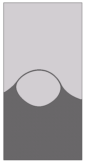
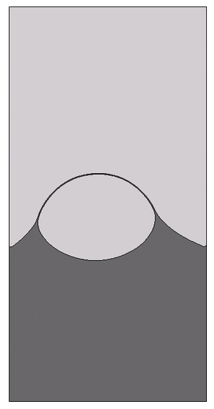
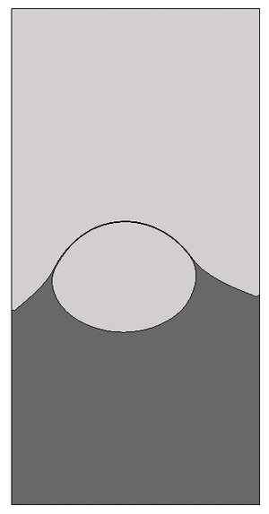
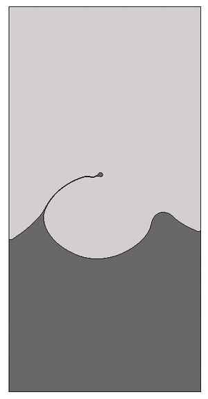
| + | For test 1, Figure [[#img-13|13]] shows the evolution of the rising bubble. At final time <math display="inline">t=3</math> s we compare the PFEM bubble shapes for the meshes <math display="inline">h=1/40, 1/80, 1/160</math> and <math display="inline">1/320</math>, and observe that they converge to the shape of the finest mesh (Figure [[#img-14|14]]), which is in good agreement with the TP2D solution reported in <span id='citeF-1'></span>[[#cite-1|[1]]] (Figure [[#img-15|15]]a). The plots of the bubble circularity (Figure [[#img-15|15]]b) and rise velocity (Figure [[#img-15|15]]d) show that our bubble is slightly oscillating, but the evolution of the center of mass (Figure [[#img-15|15]]c) is again in good agreement. The oscillating behavior of the PFEM results may be explained by the fact that, on the one side, PFEM does not introduce diffusivity at the interface, and on the other side, the geometrical method we use to calculate the curvature (the osculating circle) may not be accurate enough. Regarding the volume conservation, without any correction technique the bubble volume variation between the initial and final times, <math display="inline">\Delta V=\frac{V_f-V_0}{V_0}</math>, is of order <math display="inline">{\cal O}(10^{-4})</math> (Table [[#table-3|3]]). | ||
| + | |||
| + | <div id='img-14'></div> | ||
| + | {| class="floating_imageSCP" style="text-align: center; border: 1px solid #BBB; margin: 1em auto; width: 100%;max-width: 100%;" | ||
| + | |- | ||
| + | |[[Image:draft_Samper_466629376-test1_bubbleshape-h.png|336px|Test 1. PFEM bubble shape for different mesh sizes at t=3 s.]] | ||
| + | |- style="text-align: center; font-size: 75%;" | ||
| + | | colspan="1" | '''Figure 14:''' Test 1. PFEM bubble shape for different mesh sizes at <math>t=3</math> s. | ||
| + | |} | ||
| + | |||
| + | <div id='img-15a'></div> | ||
| + | <div id='img-15b'></div> | ||
| + | <div id='img-15c'></div> | ||
| + | <div id='img-15d'></div> | ||
| + | <div id='img-15'></div> | ||
| + | {| class="floating_imageSCP" style="text-align: center; border: 1px solid #BBB; margin: 1em auto; width: 100%;max-width: 100%;" | ||
| + | |- | ||
| + | |[[Image:draft_Samper_466629376-test1_bubbleshape-h_benchmark.png|300px|(a) Shape at t=3 s]] | ||
| + | |[[Image:draft_Samper_466629376-test1_h320_circularity.png|270px|(b) Circularity]] | ||
| + | |- style="text-align: center; font-size: 75%;" | ||
| + | | (a) Shape at <math display="inline">t=3</math> s | ||
| + | | (b) Circularity | ||
| + | |- | ||
| + | |[[Image:draft_Samper_466629376-test1_h320_centerofmass.png|270px|(c) Center of mass]] | ||
| + | |[[Image:draft_Samper_466629376-test1_h320_risevel.png|270px|(d) Rise velocity]] | ||
| + | |- style="text-align: center; font-size: 75%;" | ||
| + | | (c) Center of mass | ||
| + | | (d) Rise velocity | ||
| + | |- style="text-align: center; font-size: 75%;" | ||
| + | | colspan="2" | '''Figure 15:''' Test 1. Comparison of benchmark quantities: PFEM (<math>h=1/320</math>) vs. TP2D results. | ||
| + | |} | ||
| + | |||
| + | |||
| + | {| class="floating_tableSCP wikitable" style="text-align: center; margin: 1em auto;min-width:50%;" | ||
| + | |+ style="font-size: 75%;" |<span id='table-3'></span>Table. 3 Volume variation | ||
| + | |- style="border-top: 2px solid;" | ||
| + | | Test | ||
| + | | <math>h</math> | ||
| + | | Initial Volume | ||
| + | | Final Volume | ||
| + | | Variation | ||
| + | |- style="border-top: 2px solid;" | ||
| + | | 1 | ||
| + | | 1/320 | ||
| + | | 0.19635 | ||
| + | | 0.1965 | ||
| + | | <math>+7\times{10}^{-4}</math> | ||
| + | |- style="border-bottom: 2px solid;" | ||
| + | | 2 | ||
| + | | 1/640 | ||
| + | | 0.19635 | ||
| + | | 0.19633 | ||
| + | | <math>-1\times{10}^{-4}</math> | ||
| + | |||
| + | |} | ||
| + | |||
| + | Same type of results are shown for test 2 in Figures [[#img-16|16]], [[#img-17|17]], and [[#img-18|18]]. Although the bubbles in both test cases rise with similar velocity, the decrease in surface tension causes bubble 2 to undergo a much larger deformation and to develop thin filaments. In the TP2D and FreeLIFE solutions these filaments break up, in contrast to the moving mesh solutions of PFEM and MooNMD (Figure [[#img-18|18]]a). In the physical reality, breakup occurs due to capillary waves present on the interface, which trigger the three-dimensional Plateau-Rayleigh instability when the filament radius is small enough. Thus, capillary waves can cause the skirt filament to fragment during flow, though this response requires very large elongations, typically greater than 20 times the initial bubble radius <span id='citeF-62'></span>[[#cite-62|[62]]]. Figure [[#img-19|19]] shows the mesh of the PFEM solution in the skirted region. The filament is not thin enough to break up. The volume variation is excellent again, of order <math display="inline">{\cal O}(10^{-4})</math>. | ||
| + | |||
| + | <div id='img-16'></div> | ||
| + | {| class="floating_imageSCP" style="text-align: center; border: 1px solid #BBB; margin: 1em auto; width: 100%;max-width: 100%;" | ||
| + | |- | ||
| + | |||
| + | |- style="text-align: center; font-size: 75%;" | ||
| + | | (16) Test 2. Bubble evolution for mesh size <math>h=1/640</math>. | ||
| + | |- | ||
| + | | | ||
| + | {| style="text-align: center; margin: 1em auto;min-width:50%;width:100%;" | ||
| + | |- | ||
| + | | [[Image:draft_Samper_466629376-test2_bubble_mat_bw-01.png|300px|figures/test2_bubble_mat_bw-01.png]] | ||
| + | | [[Image:draft_Samper_466629376-test2_bubble_mat_bw-02.png|300px|figures/test2_bubble_mat_bw-02.png]] | ||
| + | | [[Image:draft_Samper_466629376-test2_bubble_mat_bw-03.png|300px|figures/test2_bubble_mat_bw-03.png]] | ||
| + | | [[Image:draft_Samper_466629376-test2_bubble_mat_bw-04.png|300px|figures/test2_bubble_mat_bw-04.png]] | ||
| + | |- | ||
| + | | (a) <math display="inline">t=0</math> s | ||
| + | | (b) <math display="inline">t=0.5</math> s | ||
| + | | (c) <math display="inline">t=1.0</math> s | ||
| + | | (d) <math display="inline">t=1.5</math> s | ||
| + | |- | ||
| + | | [[Image:draft_Samper_466629376-test2_bubble_mat_bw-05.png|300px|figures/test2_bubble_mat_bw-05.png]] | ||
| + | | [[Image:draft_Samper_466629376-test2_bubble_mat_bw-06.png|300px|figures/test2_bubble_mat_bw-06.png]] | ||
| + | | [[Image:draft_Samper_466629376-test2_bubble_mat_bw-07.png|300px|figures/test2_bubble_mat_bw-07.png]] | ||
| + | | | ||
| + | |- | ||
| + | | (e) <math display="inline">t=2.0</math> s | ||
| + | | (f) <math display="inline">t=2.5</math> s | ||
| + | | (g) <math display="inline">t=3.0</math> s | ||
| + | |} | ||
| + | |||
| + | |} | ||
| + | |||
| + | <div id='img-17'></div> | ||
| + | {| class="floating_imageSCP" style="text-align: center; border: 1px solid #BBB; margin: 1em auto; width: 100%;max-width: 100%;" | ||
| + | |- | ||
| + | |[[Image:draft_Samper_466629376-test2_bubbleshape-h.png|222px|Test 2. PFEM bubble shape for different mesh sizes at t=3 s.]] | ||
| + | |- style="text-align: center; font-size: 75%;" | ||
| + | | colspan="1" | '''Figure 17:''' Test 2. PFEM bubble shape for different mesh sizes at <math>t=3</math> s. | ||
| + | |} | ||
| + | |||
| + | <div id='img-18a'></div> | ||
| + | <div id='img-18b'></div> | ||
| + | <div id='img-18c'></div> | ||
| + | <div id='img-18d'></div> | ||
| + | <div id='img-18'></div> | ||
| + | {| class="floating_imageSCP" style="text-align: center; border: 1px solid #BBB; margin: 1em auto; width: 100%;max-width: 100%;" | ||
| + | |- | ||
| + | |[[Image:draft_Samper_466629376-test2_bubbleshape-h_benchmark.png|222px|(a) Shape at t=3 s]] | ||
| + | |[[Image:draft_Samper_466629376-test2_h640_circularity.png|258px|(b) Circularity]] | ||
| + | |- style="text-align: center; font-size: 75%;" | ||
| + | | (a) Shape at <math display="inline">t=3</math> s | ||
| + | | (b) Circularity | ||
| + | |- | ||
| + | |[[Image:draft_Samper_466629376-test2_h640_centerofmass.png|258px|(c) Center of mass]] | ||
| + | |[[Image:draft_Samper_466629376-test2_h640_risevel.png|258px|(d) Rise velocity]] | ||
| + | |- style="text-align: center; font-size: 75%;" | ||
| + | | (c) Center of mass | ||
| + | | (d) Rise velocity | ||
| + | |- style="text-align: center; font-size: 75%;" | ||
| + | | colspan="2" | '''Figure 18:''' Test 2. Benchmark quantities comparison of PFEM (black line) and TP2D (red), FreeLIFE (green) and MooNMD (blue) results. | ||
| + | |} | ||
| + | |||
| + | <div id='img-19'></div> | ||
| + | {| class="floating_imageSCP" style="text-align: center; border: 1px solid #BBB; margin: 1em auto; width: 100%;max-width: 100%;" | ||
| + | |- | ||
| + | |[[Image:draft_Samper_466629376-test2_bubble_detailskirt_bw.png|210px|Test 2. Detail of bubble skirt at t=3 s.]] | ||
| + | |- style="text-align: center; font-size: 75%;" | ||
| + | | colspan="1" | '''Figure 19:''' Test 2. Detail of bubble skirt at <math>t=3</math> s. | ||
| + | |} | ||
| + | |||
| + | The fact of using an explicit approach when discretizing in time the surface tension force introduces the stability condition for the time step expressed in Eq. ([[#eq-24|24]]). If larger time steps are taken, instabilities will develop at the interface. This time step constraint is very restrictive for fine meshes (<math display="inline">\Delta t_{st} \propto h^{3/2}</math>). In our case, the refined mesh close to the interface imposes rather small global time steps (for test 1 with mesh <math display="inline">h=1/320</math>, <math display="inline">\Delta t_{st}<3.3\times 10^{-4}</math>; and for test 2 with <math display="inline">h=1/640</math>, <math display="inline">\Delta t_{st}<3.9\times 10^{-4}</math>) that undoubtedly affect the computational efficiency. | ||
| + | |||
| + | ===7.2 Bubble breakup and coalescence=== | ||
| + | |||
| + | Topology changes in multi-fluid flows can be divided into two classes <span id='citeF-63'></span>[[#cite-63|[63]]]: | ||
| + | |||
| + | * Films that fragment. If a bubble approaches another bubble or a flat surface, the fluid in between must be squeezed out before the bubbles are sufficiently close so that the film becomes unstable to attractive forces and fragment. | ||
| + | * Threads that break. A long and thin cylinder of fluid will generally break by the Plateau-Rayleigh instability in the region where the cylinder becomes sufficiently thin so that surface tension pinches it into two. | ||
| + | |||
| + | In order to test the capabilities of PFEM to handle interfaces with changing topology, and motivated by the disagreement in the solution of test 2, we have simulated two examples on a film that fragments, namely the breakup and coalescence of bubbles. | ||
| + | |||
| + | We consider the same fluid properties and configuration of test 1. In the case of the breakup, we add a flat interface at <math display="inline">y=1</math> so that the upper region belongs to the same fluid than the bubble (see Figure [[#img-20|20]]a). The bubble rises, approaching the flat interface. The film of heavy fluid that separates the two regions of light fluid becomes thinner and thinner until it fragments and the regions fuse (Figure [[#img-20|20]]). Whereas in the physical reality the fragmentation of the film is caused by attractive forces at the microscopic scale (forces which are usually not included in the continuum description), in our simulations fragmentation is caused by a connectivity change at the interface, as illustrated in Figure [[#img-21|21]]. | ||
| + | |||
| + | <div id='img-20'></div> | ||
| + | {| class="floating_imageSCP" style="text-align: center; border: 1px solid #BBB; margin: 1em auto; width: 100%;max-width: 100%;" | ||
| + | |- | ||
| + | | | ||
| + | {| style="text-align: center; margin: 1em auto;min-width:50%;width:100%;" | ||
| + | |- | ||
| + | | [[Image:draft_Samper_466629376-bubblebreakup_mat_bw-01.png|300px|figures/bubblebreakup_mat_bw-01.png]] | ||
| + | | [[Image:draft_Samper_466629376-bubblebreakup_mat_bw-02.png|300px|figures/bubblebreakup_mat_bw-02.png]] | ||
| + | | [[Image:draft_Samper_466629376-bubblebreakup_mat_bw-03.png|300px|figures/bubblebreakup_mat_bw-03.png]] | ||
| + | | [[Image:draft_Samper_466629376-bubblebreakup_mat_bw-04.png|300px|figures/bubblebreakup_mat_bw-04.png]] | ||
| + | |- | ||
| + | | (a) <math display="inline">t=0</math> s | ||
| + | | (b) <math display="inline">t=1.5</math> s | ||
| + | | (c) <math display="inline">t=2.5</math> s | ||
| + | | (d) <math display="inline">t=3.5</math> s | ||
| + | |- | ||
| + | | [[Image:draft_Samper_466629376-bubblebreakup_mat_bw-05.png|300px|figures/bubblebreakup_mat_bw-05.png]] | ||
| + | | [[Image:draft_Samper_466629376-bubblebreakup_mat_bw-06.png|300px|figures/bubblebreakup_mat_bw-06.png]] | ||
| + | | [[Image:draft_Samper_466629376-bubblebreakup_mat_bw-07.png|300px|figures/bubblebreakup_mat_bw-07.png]] | ||
| + | | [[Image:draft_Samper_466629376-bubblebreakup_mat_bw-08.png|300px|figures/bubblebreakup_mat_bw-08.png]] | ||
| + | |- | ||
| + | | (e) <math display="inline">t=4.5</math> s | ||
| + | | (f) <math display="inline">t=5.5</math> s | ||
| + | | (g) <math display="inline">t=6.0</math> s | ||
| + | | (h) <math display="inline">t=6.5</math> s | ||
| + | |} | ||
| + | |||
| + | |- | ||
| + | |||
| + | |- style="text-align: center; font-size: 75%;" | ||
| + | | colspan="1" | '''Figure 20:''' Bubble breakup. | ||
| + | |} | ||
| + | |||
| + | One of the main difficulties we face in our Lagrangian approach is the connectivity changes introduced by the remeshing process. In general, these reconnections may alter the equilibrium at the interface, slow down convergence and affect mass conservation. Thus, in interfacial flows it is essential to avoid them. We are using an unconstrained Delaunay triangulator which does not allow to fix connectivities. Therefore, to ensure that a specific connectivity remains, we refine long interfacial edges and remove nodes too close to the interface. Unfortunately, this strategy would preclude the possibility of breakup, as the interface could elongate endlessly. In the way PFEM defines interfaces, it is possible to have fluid regions spanned by just one element layer. The ''breakup criterium'' we have implemented in PFEM is to permit connectivity changes in elements where all nodes lie at the interface. In this way, a thin fluid thread can stop elongating and fragment. Breakup is then dependent on the mesh resolution, that is, it happens when the thickness of the film is similar to the mesh resolution of the interface. This is not a drawback specific of PFEM, breakup is mesh dependent in front-capturing methods as well. For example, in the level set method, two interfaces are described as two different zero contours of the same level set function, and these interfaces will automatically merge once they get close enough, relative to the spatial resolution of the mesh where the level set function is defined. The resolution determines the smallest distance between two zero level sets of the level set function for which they can still be distinguished as separate zero contours. Interfaces can in fact merge faster due to the diffusivity of the schemes used for advection and reinitialization of the level set function <span id='citeF-27'></span>[[#cite-27|[27]]]. | ||
| + | |||
| + | <div id='img-21a'></div> | ||
| + | <div id='img-21b'></div> | ||
| + | <div id='img-21'></div> | ||
| + | {| class="floating_imageSCP" style="text-align: center; border: 1px solid #BBB; margin: 1em auto; width: 100%;max-width: 100%;" | ||
| + | |- | ||
| + | |[[Image:draft_Samper_466629376-bubblebreakup_step1_bw.png|240px|(a) tⁿ]] | ||
| + | |[[Image:draft_Samper_466629376-bubblebreakup_step2_bw.png|240px|(b) tⁿ⁺¹]] | ||
| + | |- style="text-align: center; font-size: 75%;" | ||
| + | | (a) <math display="inline">t^n</math> | ||
| + | | (b) <math display="inline">t^{n+1}</math> | ||
| + | |- style="text-align: center; font-size: 75%;" | ||
| + | | colspan="2" | '''Figure 21:''' Connectivity change that produces breakup at fluid films spanned by just one mesh element. | ||
| + | |} | ||
| + | |||
| + | The pressure field at and after breakup is shown in Figures [[#img-22|22]] and [[#img-23|23]]. The different pressure values inside and outside the bubble equilibrate after breakup, what occurs at <math display="inline">t=5.97</math> s. | ||
| + | |||
| + | <div id='img-22a'></div> | ||
| + | <div id='img-22b'></div> | ||
| + | <div id='img-22c'></div> | ||
| + | <div id='img-22d'></div> | ||
| + | <div id='img-22'></div> | ||
| + | {| class="floating_imageSCP" style="text-align: center; border: 1px solid #BBB; margin: 1em auto; width: 100%;max-width: 100%;" | ||
| + | |- | ||
| + | |[[Image:draft_Samper_466629376-bubblebreakup_pres2-01.png|240px|(a) t=5.965 s]] | ||
| + | |[[Image:draft_Samper_466629376-bubblebreakup_pres2-02.png|240px|(b) t=5.97 s]] | ||
| + | |- style="text-align: center; font-size: 75%;" | ||
| + | | (a) <math display="inline">t=5.965</math> s | ||
| + | | (b) <math display="inline">t=5.97</math> s | ||
| + | |- | ||
| + | |[[Image:draft_Samper_466629376-bubblebreakup_pres2-03.png|240px|(c) t=5.975 s]] | ||
| + | |[[Image:draft_Samper_466629376-bubblebreakup_pres2-04.png|240px|(d) t=5.98 s]] | ||
| + | |- style="text-align: center; font-size: 75%;" | ||
| + | | (c) <math display="inline">t=5.975</math> s | ||
| + | | (d) <math display="inline">t=5.98</math> s | ||
| + | |- style="text-align: center; font-size: 75%;" | ||
| + | | colspan="2" | '''Figure 22:''' Pressure field at breakup (variable scale ranges in legend). | ||
| + | |} | ||
| + | |||
| + | <div id='img-23a'></div> | ||
| + | <div id='img-23b'></div> | ||
| + | <div id='img-23c'></div> | ||
| + | <div id='img-23d'></div> | ||
| + | <div id='img-23'></div> | ||
| + | {| class="floating_imageSCP" style="text-align: center; border: 1px solid #BBB; margin: 1em auto; width: 100%;max-width: 100%;" | ||
| + | |- | ||
| + | |[[Image:draft_Samper_466629376-bubblebreakup_pres2-05.png|240px|(a) t=6.0 s]] | ||
| + | |[[Image:draft_Samper_466629376-bubblebreakup_pres2-06.png|240px|(b) t=6.05 s]] | ||
| + | |- style="text-align: center; font-size: 75%;" | ||
| + | | (a) <math display="inline">t=6.0</math> s | ||
| + | | (b) <math display="inline">t=6.05</math> s | ||
| + | |- | ||
| + | |[[Image:draft_Samper_466629376-bubblebreakup_pres2-07.png|240px|(c) t=6.125 s]] | ||
| + | |[[Image:draft_Samper_466629376-bubblebreakup_pres2-08.png|240px|(d) t=6.18 s]] | ||
| + | |- style="text-align: center; font-size: 75%;" | ||
| + | | (c) <math display="inline">t=6.125</math> s | ||
| + | | (d) <math display="inline">t=6.18</math> s | ||
| + | |- style="text-align: center; font-size: 75%;" | ||
| + | | colspan="2" | '''Figure 23:''' Pressure field after breakup (variable scale ranges in legend). | ||
| + | |} | ||
| + | |||
| + | For the simulation of bubble coalescence, we consider the same rectangular domain <math display="inline">(0,1)\times (0,2)</math> as before, with two circular bubbles inside. The center of the first bubble is <math display="inline">(0.5,1.0)</math> and its radius is equal to 0.25, the center of the second bubble is <math display="inline">(0.5,0.5)</math> and the radius 0.2. Since the small bubble is located close to the large one, this lower bubble turns out to be in the wake of the upper bubble and rises faster than that. Figure [[#img-24|24]] shows the coalescence process. The mechanism is again the rupture of the thin film between the bubbles. This happens not during the impact of the bubbles (around <math display="inline">t=2.5</math> s) but during the separation after impact, as corresponds to the physical reality <span id='citeF-64'></span>[[#cite-64|[64]]]. | ||
| + | |||
| + | <div id='img-24'></div> | ||
| + | {| class="floating_imageSCP" style="text-align: center; border: 1px solid #BBB; margin: 1em auto; width: 100%;max-width: 100%;" | ||
| + | |- | ||
| + | | | ||
| + | {| style="text-align: center; margin: 1em auto;min-width:50%;width:100%;" | ||
| + | |- | ||
| + | | [[Image:draft_Samper_466629376-bubblemerge_mat_bw-01.png|300px|figures/bubblemerge_mat_bw-01.png]] | ||
| + | | [[Image:draft_Samper_466629376-bubblemerge_mat_bw-02.png|300px|figures/bubblemerge_mat_bw-02.png]] | ||
| + | | [[Image:draft_Samper_466629376-bubblemerge_mat_bw-03.png|300px|figures/bubblemerge_mat_bw-03.png]] | ||
| + | | [[Image:draft_Samper_466629376-bubblemerge_mat_bw-04.png|300px|figures/bubblemerge_mat_bw-04.png]] | ||
| + | |- | ||
| + | | (a) <math display="inline">t=0</math> s | ||
| + | | (b) <math display="inline">t=0.5</math> s | ||
| + | | (c) <math display="inline">t=1.0</math> s | ||
| + | | (d) <math display="inline">t=1.5</math> s | ||
| + | |- | ||
| + | | [[Image:draft_Samper_466629376-bubblemerge_mat_bw-05.png|300px|figures/bubblemerge_mat_bw-05.png]] | ||
| + | | [[Image:draft_Samper_466629376-bubblemerge_mat_bw-06.png|300px|figures/bubblemerge_mat_bw-06.png]] | ||
| + | | [[Image:draft_Samper_466629376-bubblemerge_mat_bw-07.png|300px|figures/bubblemerge_mat_bw-07.png]] | ||
| + | | [[Image:draft_Samper_466629376-bubblemerge_mat_bw-08.png|300px|figures/bubblemerge_mat_bw-08.png]] | ||
| + | |- | ||
| + | | (e) <math display="inline">t=2.0</math> s | ||
| + | | (f) <math display="inline">t=2.5</math> s | ||
| + | | (g) <math display="inline">t=3.0</math> s | ||
| + | | (h) <math display="inline">t=3.5</math> s | ||
| + | |- | ||
| + | | [[Image:draft_Samper_466629376-bubblemerge_mat_bw-09.png|300px|figures/bubblemerge_mat_bw-09.png]] | ||
| + | | [[Image:draft_Samper_466629376-bubblemerge_mat_bw-10.png|300px|figures/bubblemerge_mat_bw-10.png]] | ||
| + | | [[Image:draft_Samper_466629376-bubblemerge_mat_bw-12.png|300px|figures/bubblemerge_mat_bw-12.png]] | ||
| + | | [[Image:draft_Samper_466629376-bubblemerge_mat_bw-13.png|300px|figures/bubblemerge_mat_bw-13.png]] | ||
| + | |- | ||
| + | | (i) <math display="inline">t=4.0</math> s | ||
| + | | (j) <math display="inline">t=4.5</math> s | ||
| + | | (k) <math display="inline">t=5.0</math> s | ||
| + | | (l) <math display="inline">t=10.0</math> s | ||
| + | |} | ||
| + | |||
| + | |- | ||
| + | |||
| + | |- style="text-align: center; font-size: 75%;" | ||
| + | | colspan="1" | '''Figure 24:''' Bubble coalescence. | ||
| + | |} | ||
| + | |||
| + | ==8 SUMMARY AND CONCLUSIONS== | ||
| + | |||
| + | We have developed a numerical scheme for the simulation of multi-fluid flows with the Particle Finite Element Method able to deal with large jumps in the physical properties (included surface tension), and able to accurately represent the <math display="inline">{\cal C}^{-1}</math> and <math display="inline">{\cal C}^0</math> discontinuities in the flow variables. Interfaces are tracked by the moving mesh, pressure degrees of freedom have been duplicated at the interface nodes to represent the <math display="inline">{\cal C}^{-1}</math> discontinuity of this variable due to surface tension and variable viscosity (Eq. [[#eq-9|9]]), velocity and pressure variables have been decoupled through a pressure segregation method, and the mesh has been refined in the vicinity of the interface to improve the accuracy and efficiency of the computations. | ||
| + | |||
| + | We have first tested the scheme in a simple static bubble problem and compared the results for continuous and discontinuous pressure approximations. We have then applied the method to the more complicated rising bubble problem presented in Hysing et al. <span id='citeF-1'></span>[[#cite-1|[1]]]. We can conclude that PFEM solutions for the single rising bubble are in good agreement with those reported in <span id='citeF-1'></span>[[#cite-1|[1]]]. For test 1, our bubble is slightly oscillating in contrast to the reference solution. A reason for this may be that PFEM does not introduce diffusion at the interface. In any case, more comparisons with other methods are needed. For test 2, although PFEM can handle interface breakup without problems (as shown in Section [[#7.2 Bubble breakup and coalescence|7.2]]), the skirt filaments remain intact. Breakup happens only when the fluid region is spanned by just one element layer. This allows to model thin films of thickness <math display="inline">h</math>, being <math display="inline">h</math> the mesh size at the interface. In both tests, we have achieved an excellent mass conservation without any correction. | ||
| + | |||
| + | Finally, we propose two bubble breakup and coalescence problems as benchmarks for testing the capabilities of multi-fluid flow codes to handle topology changes of the interface. | ||
| + | |||
| + | ===BIBLIOGRAPHY=== | ||
| + | |||
| + | <div id="cite-1"></div> | ||
| + | '''[[#citeF-1|[1]]]''' Hysing, S. and Turek, S. and D. Kuzmin and N. Parolini and E. Burman and S. Ganesan and L. Tobiska. (2009) "Quantitative benchmark computations of two-dimensional bubble dynamics", Volume 60. International Journal for Numerical Methods in Fluids 1259-1288 | ||
| + | |||
| + | <div id="cite-2"></div> | ||
| + | '''[[#citeF-2|[2]]]''' Idelsohn, S.R. and Mier-Torrecilla, M. and Oñate, E. (2009) "Multi-fluid flows with the Particle Finite Element Method", Volume 198. Computer Methods in Applied Mechanics and Engineering 2750-2767 | ||
| + | |||
| + | <div id="cite-3"></div> | ||
| + | '''[[#citeF-3|[3]]]''' G.K. Batchelor. (1967) "An introduction to fluid dynamics". Cambridge University Press | ||
| + | |||
| + | <div id="cite-4"></div> | ||
| + | '''[[#citeF-4|[4]]]''' Idelsohn, S.R. and Mier-Torrecilla, M. and Nigro, N. and Oñate, E. (2009) "On the analysis of heterogeneous fluids with jumps in the viscosity using a discontinuous pressure field", Volume In press. Computational Mechanics | ||
| + | |||
| + | <div id="cite-5"></div> | ||
| + | '''[[#citeF-5|[5]]]''' Unverdi, S.O. and Tryggvason, G. (1992) "Computations of multi-fluid flows", Volume 60. Physica D: Nonlinear Phenomena 70-83 | ||
| + | |||
| + | <div id="cite-6"></div> | ||
| + | '''[[#citeF-6|[6]]]''' W. Shyy. (1996) "Computational Fluid Dynamics with moving boundaries". Taylor&Francis | ||
| + | |||
| + | <div id="cite-7"></div> | ||
| + | '''[[#citeF-7|[7]]]''' Scardovelli, R. and Zaleski, S. (1999) "Direct Numerical Simulation of free-surface and interfacial flow", Volume 31. Annual Reviews of Fluid Mechanics 567-603 | ||
| + | |||
| + | <div id="cite-8"></div> | ||
| + | '''[[#citeF-8|[8]]]''' Caboussat, A. (2005) "Numerical simulation of two-phase free surface flows", Volume 12. Archives of Computational Methods in Engineering 165-224 | ||
| + | |||
| + | <div id="cite-9"></div> | ||
| + | '''[[#citeF-9|[9]]]''' Hughes, T.J.R. and Liu, W.K. and Zimmermann, T.K. (1981) "Lagrangian-Eulerian finite element element formulation for incompressible viscous flows", Volume 29. Computer Methods in Applied Mechanics and Engineering 239-349 | ||
| + | |||
| + | <div id="cite-10"></div> | ||
| + | '''[[#citeF-10|[10]]]''' B. Ramaswamy and M. Kawahara. (1986) "Arbitrary Lagrangian-Eulerian finite element method for the analysis of free surface fluid flows", Volume 1. Computational Mechanics 103-108 | ||
| + | |||
| + | <div id="cite-11"></div> | ||
| + | '''[[#citeF-11|[11]]]''' T.E. Tezduyar and M. Behr and J. Liou. (1992) "A new strategy for finite element computations involving moving boundaries and interfaces. The deforming-spatial-domain/space-time procedure: I. The concept and preliminary numerical tests", Volume 94. Computer Methods in Applied Mechanics and Engineering 339-351 | ||
| + | |||
| + | <div id="cite-12"></div> | ||
| + | '''[[#citeF-12|[12]]]''' T.E. Tezduyar and M. Behr and S. Mittal and J. Liou. (1992) "A new strategy for finite element computations involving moving boundaries and interfaces. The deforming-spatial-domain/space-time procedure: II. Computation of free-surface flows, two-liquid flows and flows with drifting cylinders", Volume 94. Computer Methods in Applied Mechanics and Engineering 353-371 | ||
| + | |||
| + | <div id="cite-13"></div> | ||
| + | '''[[#citeF-13|[13]]]''' Hirt, C.W. and Cook, J.L. and Butler, T.D. (1970) "A Lagrangian method for calculating the dynamics of an incompressible fluid with free surface", Volume 5. Journal of Computational Physics 103-124 | ||
| + | |||
| + | <div id="cite-14"></div> | ||
| + | '''[[#citeF-14|[14]]]''' B. Ramaswamy and M. Kawahara. (1987) "Lagrangian finite element analysis applied to viscous free surface fluid flow", Volume 7. International Journal for Numerical Methods in Fluids 953-984 | ||
| + | |||
| + | <div id="cite-15"></div> | ||
| + | '''[[#citeF-15|[15]]]''' Idelsohn, S.R. and Oñate, E. and Del Pin, F. (2003) "A Lagrangian meshless finite element method applied to fluid-structure interaction problems", Volume 81. Computers and Structures 8–11 655–671 | ||
| + | |||
| + | <div id="cite-16"></div> | ||
| + | '''[[#citeF-16|[16]]]''' Idelsohn, S.R. and Oñate, E. and Del Pin, F. (2004) "The Particle Finite Element Method: A powerful tool to solve incompressible flows with free-surfaces and breaking waves", Volume 61. International Journal for Numerical Methods in Engineering 7 964–989 | ||
| + | |||
| + | <div id="cite-17"></div> | ||
| + | '''[[#citeF-17|[17]]]''' Oñate, E. and Idelsohn, S.R. and Del Pin, F. and Aubry, R. (2004) "The Particle Finite Element Method: An Overview", Volume 1. International Journal of Computational Methods 2 267–307 | ||
| + | |||
| + | <div id="cite-18"></div> | ||
| + | '''[[#citeF-18|[18]]]''' Del Pin, F. and Idelsohn, S.R. and Oñate, E. and Aubry, R. (2007) "The ALE/Lagrangian Particle Finite Element Method: A new approach to computation of free-surfaces flows and fluid-object interactions", Volume 36. Computers and Fluids 1 27–38 | ||
| + | |||
| + | <div id="cite-19"></div> | ||
| + | '''[[#citeF-19|[19]]]''' Harlow, F.H. (1964) "The Particle-in-Cell computing method for fluid dynamics", Volume 3. Methods in Computational Physics 313-343 | ||
| + | |||
| + | <div id="cite-20"></div> | ||
| + | '''[[#citeF-20|[20]]]''' Unverdi, S.O. and Tryggvason, G. (1992) "A front-tracking method for viscous, incompressible, multi-fluid flows", Volume 100. Journal of Computational Physics 25-37 | ||
| + | |||
| + | <div id="cite-21"></div> | ||
| + | '''[[#citeF-21|[21]]]''' Hirt, C. and Nichols, B. (1981) "Volume of Fluid (VOF) method for the dynamics of free boundaries", Volume 39. Journal of Computational Physics 201-225 | ||
| + | |||
| + | <div id="cite-22"></div> | ||
| + | '''[[#citeF-22|[22]]]''' Osher, S. and Sethian, J. (1988) "Fronts propagating with curvature dependant speed: algorithms based on Hamilton-Jacobi formulations", Volume 79. Journal of Computational Physics 12-49 | ||
| + | |||
| + | <div id="cite-23"></div> | ||
| + | '''[[#citeF-23|[23]]]''' Idelsohn, S.R. and Calvo, N. and Oñate, E. (2003) "Polyhedrization of an arbitrary 3D point set", Volume 192. Computer Methods in Applied Mechanics and Engineering 2649-2667 | ||
| + | |||
| + | <div id="cite-24"></div> | ||
| + | '''[[#citeF-24|[24]]]''' Oñate, E. and Idelsohn, S.R. and Celigueta, M.A. and Rossi, R. (2008) "Advances in the Particle Finite Element Method for the analysis of fluid-multibody interaction and bed erosion in free surface flows", Volume 197. Computer Methods in Applied Mechanics and Engineering 1777-1800 | ||
| + | |||
| + | <div id="cite-25"></div> | ||
| + | '''[[#citeF-25|[25]]]''' van Kan, J. (1986) "A second-order accurate pressure correction scheme for viscous incompressible flow", Volume 7. SIAM Journal on Scientific and Statistical Computing 870-891 | ||
| + | |||
| + | <div id="cite-26"></div> | ||
| + | '''[[#citeF-26|[26]]]''' A. Smolianski. (2001) "Numerical Modeling of Two Fluid Interfacial Flows". University of Jyväskylä | ||
| + | |||
| + | <div id="cite-27"></div> | ||
| + | '''[[#citeF-27|[27]]]''' A.-K. Tornberg. (2000) "Interface Tracking Methods with Application to Multiphase Flows". Royal Institute of Technology, Stockholm | ||
| + | |||
| + | <div id="cite-28"></div> | ||
| + | '''[[#citeF-28|[28]]]''' Minev, P.D. and Chen, T. and Nandakumar, K. (2003) "A finite element technique for multifluid incompressible flow using Eulerian grids", Volume 187. Journal of Computational Physics 255-273 | ||
| + | |||
| + | <div id="cite-29"></div> | ||
| + | '''[[#citeF-29|[29]]]''' Coppola-Owen, A.H. and Codina, R. (2005) "Improving Eulerian two-phase flow finite element approximation with discontinuous gradient pressure shape functions", Volume 49. International Journal for Numerical Methods in Fluids 1287-1304 | ||
| + | |||
| + | <div id="cite-30"></div> | ||
| + | '''[[#citeF-30|[30]]]''' J. Chessa and T. Belytschko. (2003) "An extended finite element method for two-phase fluids", Volume 70. ASME Journal of Applied Mechanics 10-17 | ||
| + | |||
| + | <div id="cite-31"></div> | ||
| + | '''[[#citeF-31|[31]]]''' S. Gross and A. Reusken. (2007) "An extended pressure finite element space for two-phase incompressible flows with surface tension", Volume 224. Journal of Computational Physics 40-58 | ||
| + | |||
| + | <div id="cite-32"></div> | ||
| + | '''[[#citeF-32|[32]]]''' Juntunen, M. and Stenberg, R. (2007) "Nitsche's method for general boundary conditions". Research Reports A530, University of Technology, Institute of Mathematics | ||
| + | |||
| + | <div id="cite-33"></div> | ||
| + | '''[[#citeF-33|[33]]]''' Mier-Torrecilla, M. (2010) "Numerical simulation of multi-fluid flows with the Particle Finite Element Method". Technical University of Catalonia | ||
| + | |||
| + | <div id="cite-34"></div> | ||
| + | '''[[#citeF-34|[34]]]''' J.U. Brackbill and D.B. Kothe and C. Zemach. (1992) "A continuum method for modeling surface tension", Volume 100. Journal of Computational Physics 335-354 | ||
| + | |||
| + | <div id="cite-35"></div> | ||
| + | '''[[#citeF-35|[35]]]''' Bänsch, E. (2001) "Finite Element discretization of the Navier-Stokes equations with a free capillary surface", Volume 88. Numerische Mathematik 203-235 | ||
| + | |||
| + | <div id="cite-36"></div> | ||
| + | '''[[#citeF-36|[36]]]''' Hysing, S. (2006) "A new implicit surface tension implementation for interfacial flows", Volume 51. International Journal for Numerical Methods in Fluids 659-672 | ||
| + | |||
| + | <div id="cite-37"></div> | ||
| + | '''[[#citeF-37|[37]]]''' Popinet, S. and Zaleski, S. (1999) "A front tracking algorithm for accurate representation of surface tension", Volume 30. International Journal for Numerical Methods in Fluids 775-793 | ||
| + | |||
| + | <div id="cite-38"></div> | ||
| + | '''[[#citeF-38|[38]]]''' Sussman, M. and Smereka, P. and Osher, S. (1994) "A level set approach for computing solutions to incompressible two-phase flows", Volume 114. Journal of Computational Physics 146-159 | ||
| + | |||
| + | <div id="cite-39"></div> | ||
| + | '''[[#citeF-39|[39]]]''' Grace, J. R. (1973) "Shapes and Velocities of Bubbles Rising in Infinite Liquids", Volume 51. Transactions of the Institution of Chemical Engineers 116-120 | ||
| + | |||
| + | <div id="cite-40"></div> | ||
| + | '''[[#citeF-40|[40]]]''' R. Clift and J.R. Grace and M.E. Weber. (1978) "Bubbles, drops and particles". Academic Press | ||
| + | |||
| + | <div id="cite-41"></div> | ||
| + | '''[[#citeF-41|[41]]]''' Bhaga, D. and Weber, M.E. (1981) "Bubbles in viscous liquids: shapes, wakes and velocities", Volume 105. Journal of Fluid Mechanics 61-85 | ||
| + | |||
| + | <div id="cite-42"></div> | ||
| + | '''[[#citeF-42|[42]]]''' Haberman, W. L. and Morton, R. K. (1954) "An experimental study of bubbles moving in liquids", Volume 387. Proceedings of the American Society of Civil Engineers 1-25 | ||
| + | |||
| + | <div id="cite-43"></div> | ||
| + | '''[[#citeF-43|[43]]]''' Hnat, J. G. and Buckmaster, J. D. (1976) "Spherical cap bubbles and skirt formation", Volume 19. Physics of Fluids 182-194 | ||
| + | |||
| + | <div id="cite-44"></div> | ||
| + | '''[[#citeF-44|[44]]]''' Maxworthy, T. and Gnann, C. and Kuerten, M. and Durst, F. (1996) "Experiments on the rise of air bubbles in clean viscous liquids", Volume 321. Journal of Fluid Mechanics 421-441 | ||
| + | |||
| + | <div id="cite-45"></div> | ||
| + | '''[[#citeF-45|[45]]]''' F. Raymond and J.M. Rosant. (2000) "A numerical and experimental study of the terminal velocity and shape of bubbles in viscous liquids", Volume 55. Chemical Engineering Science 943-955 | ||
| + | |||
| + | <div id="cite-46"></div> | ||
| + | '''[[#citeF-46|[46]]]''' M. Wu and M. Gharib. (2002) "Experimental Studies on the Shape and Path of Small Air Bubbles Rising in Clean Water", Volume 14. Physics of Fluids 49-52 | ||
| + | |||
| + | <div id="cite-47"></div> | ||
| + | '''[[#citeF-47|[47]]]''' Esmaeeli, A. and Tryggvason, G. (1998) "Direct numerical simulations of bubbly flows. Part 1. Low Reynolds number arrays", Volume 377. Journal of Fluid Mechanics 313-345 | ||
| + | |||
| + | <div id="cite-48"></div> | ||
| + | '''[[#citeF-48|[48]]]''' Esmaeeli, A. and Tryggvason, G. (1999) "Direct numerical simulations of bubbly flows. Part 2. Moderate Reynolds number arrays", Volume 385. Journal of Fluid Mechanics 325-358 | ||
| + | |||
| + | <div id="cite-49"></div> | ||
| + | '''[[#citeF-49|[49]]]''' Bunner, B. and Tryggvason, G. (2002) "Dynamics of homogeneous bubbly flows. Part 1. Rise velocity and microstructure of the bubbles", Volume 466. Journal of Fluid Mechanics 17-52 | ||
| + | |||
| + | <div id="cite-50"></div> | ||
| + | '''[[#citeF-50|[50]]]''' F.S. de Sousa and N. Mangiavacchi and L.G. Nonato and A. Castelo and M.F. Tomé and V.G. Ferreira and J.A. Cuminato and S. McKee. (2004) "A front-tracking/front-capturing method for the simulation of 3D multi-fluid flows with free surfaces", Volume 198. Journal of Computational Physics 469-499 | ||
| + | |||
| + | <div id="cite-51"></div> | ||
| + | '''[[#citeF-51|[51]]]''' Hua, J. and Lou, J. (2007) "Numerical simulation of bubble rising in viscous liquid", Volume 222. Journal of Computational Physics 769-795 | ||
| + | |||
| + | <div id="cite-52"></div> | ||
| + | '''[[#citeF-52|[52]]]''' Z. Yu and L.-S. Fan. (2008) "Direct Simulation of the Buoyant Rise of Bubbles in Infinite Liquid Using Level Set Method", Volume 86. Canadian Journal of Chemical Engineering 267-275 | ||
| + | |||
| + | <div id="cite-53"></div> | ||
| + | '''[[#citeF-53|[53]]]''' L. Chen and S.V. Garimella and J.A. Reizes and E. Leonardi. (1999) "The development of a bubble rising in a viscous liquid", Volume 387. Journal of Fluid Mechanics 61-96 | ||
| + | |||
| + | <div id="cite-54"></div> | ||
| + | '''[[#citeF-54|[54]]]''' Van Sint Annaland, M. and N. G. Deen and J. A. M. Kuipers. (2005) "Numerical Simulation of Gas Bubbles Behavior Using a Three-Dimensional Volume of Fluid Method", Volume 60. Chemical Engineering Science 2999-3011 | ||
| + | |||
| + | <div id="cite-55"></div> | ||
| + | '''[[#citeF-55|[55]]]''' Bonometti, T. and Magnaudet, J. (2007) "An interface-capturing method for incompressible two-phase flows. Validation and application to bubble dynamics", Volume 33. International Journal of Multiphase Flow 109-133 | ||
| + | |||
| + | <div id="cite-56"></div> | ||
| + | '''[[#citeF-56|[56]]]''' Ryskin, G. and Leal, L. G. (1984) "Numerical solution of free-boundary problems in fluid mechanics. Part 2. Buoyancy-driven motion of a gas bubble through a quiescent liquid", Volume 148. Journal of Fluid Mechanics 19-35 | ||
| + | |||
| + | <div id="cite-57"></div> | ||
| + | '''[[#citeF-57|[57]]]''' X. Frank and D. Funfschilling and N. Midoux and H. Z. Li. (2006) "Bubbles in a viscous liquid: Lattice Boltzmann simulation and experimental validation", Volume 546. Journal of Fluid Mechanics 113-122 | ||
| + | |||
| + | <div id="cite-58"></div> | ||
| + | '''[[#citeF-58|[58]]]''' I. O. Kurtoglu and C. L. Lin. (2006) "Lattice Boltzmann Study of Bubble Dynamics", Volume 50. Numerical Heat Transfer B 333-351 | ||
| + | |||
| + | <div id="cite-59"></div> | ||
| + | '''[[#citeF-59|[59]]]''' S. Turek. (1998) "Efficient Solvers for Incompressible Flow Problems". Springer | ||
| + | |||
| + | <div id="cite-60"></div> | ||
| + | '''[[#citeF-60|[60]]]''' Parolini, N. and Burman, E. (2005) "A finite element level set method for viscous free-surface flows". 7th Conference on Applied and Industrial Mathematics in Italy 416-427 | ||
| + | |||
| + | <div id="cite-61"></div> | ||
| + | '''[[#citeF-61|[61]]]''' Ganesan, S. and Matthies, G. and Tobiska, L. (2007) "On spurious velocities in incompressible flow problem with interfaces", Volume 196. Computer Methods in Applied Mechanics and Engineering 1193-1202 | ||
| + | |||
| + | <div id="cite-62"></div> | ||
| + | '''[[#citeF-62|[62]]]''' Stone, H. (1994) "Dynamics of drop deformation and breakup in viscous fluids", Volume 26. Annual Reviews of Fluid Mechanics 65-102 | ||
| + | |||
| + | <div id="cite-63"></div> | ||
| + | '''[[#citeF-63|[63]]]''' Tryggvason, G. and Bunner, B. and Esmaeeli, A. and Juric, D. and Al-Rawahi, N. and Tauber, W. and Han, J. and Nas, S. and Jan, Y.-J. (2001) "A front-tracking method for the computations of multiphase flow", Volume 169. Journal of Computational Physics 708-759 | ||
| + | |||
| + | <div id="cite-64"></div> | ||
| + | '''[[#citeF-64|[64]]]''' N. Bremond and A. Thiam and J. Bibette. (2008) "Decompressing Emulsion Droplets Favors Coalescence", Volume 100. Physical Review Letters | ||
Latest revision as of 11:43, 17 June 2019
Abstract
In this work we extend the Particle Finite Element Method (PFEM) to multi-fluid flow problems with the aim of exploiting the fact that Lagrangian methods are specially well suited for tracking interfaces. We develop a numerical scheme able to deal with large jumps in the physical properties, included surface tension, and able to accurately represent all types of discontinuities in the flow variables. The scheme is based on decoupling the velocity and pressure variables through a pressure segregation method which takes into account the interface conditions. The interface is defined to be aligned with the moving mesh, so that it remains sharp along time, and pressure degrees of freedom are duplicated at the interface nodes to represent the discontinuity of this variable due to surface tension and variable viscosity. Furthermore, the mesh is refined in the vicinity of the interface to improve the accuracy and the efficiency of the computations.
We apply the resulting scheme to the benchmark problem of a two-dimensional bubble rising in a liquid column presented in [1], and propose two breakup and coalescence problems to assess the ability of a multi-fluid code to model topology changes.
Keywords: Particle Finite Element Method (PFEM); Lagrangian simulation; multi-fluid flows; pressure segregation; surface tension; bubble dynamics.
1 INTRODUCTION
The simultaneous presence of multiple fluids with different properties in external or internal flows is found in daily life, environmental problems, and numerous industrial processes. Examples are fluid-fuel interaction in enhanced oil recovery, blending of polymers, emulsions in food manufacturing, rain droplet formation in clouds, fuel injection in engines, and bubble column reactors, to name only a few. Although multi-fluid flows occur frequently in nature and engineering practice, they still pose a major research challenge from both theoretical and computational points of view.
In the case of immiscible fluids, the dynamics of the interface between fluids plays a dominant role. The success of the simulation of such flows depends on the ability of the numerical method to model accurately the interface and the phenomena taking place on it, such as the surface tension. The origin of the surface tension force lies in the different intermolecular attractive forces that act in the two fluids, and the result is an interfacial energy per area that acts to resist the creation of new interface, so that the interface behaves like a stretched membrane trying to minimize its area.
The main difference between a single-fluid flow (homogeneous) and a multi-fluid (heterogeneous) one is the presence of internal interfaces. In addition to the well-known difficulties in the simulation of homogeneous flows, namely the coupling of pressure and velocity through the incompressibility constraint, the need of the discretization spaces to satisfy the inf-sup condition, and the non-linearity of the governing equations, numerical methods for heterogeneous flows face the following challenges:
- Accurate definition of the interface position. The interface separating the fluids needs to be tracked accurately without introducing excessive numerical smoothing.
- Modeling the jumps in the fluid properties across the interface. Large jumps of fluid density and viscosity across the interface need to be properly taken into account in order to satisfy the momentum balance at the vicinity of the interface.
- Modeling the discontinuities of the flow variables across the interface. Velocity and pressure may be discontinuous across the interface under certain conditions.
- Modeling the surface tension. Since surface tension plays a very important role in the immiscible interface dynamics, this force needs to be accurately evaluated and incorporated into the model.
This paper extends the work of the authors in the study of multi-fluid flows with the Particle Finite Element Method [2]. The new contributions include the scheme for describing the interface, the computation of surface tension and the enhanced pressure segregation approach. We have found that these developments are essential for accurately modeling of bubble dynamics. The paper is organized as follows: In Section 2 we present the governing equations together with the interface conditions and the possible discontinuities of the flow variables. In Section 3 we briefly review the interface descriptions most used in the literature, to focus later in the Particle Finite Element Method (Section 4) and the numerical scheme we have developed (Sections 5 and 6). Finally, in Section 7 we apply the PFEM to the solution of the two-dimensional bubble rise, breakup and coalescence problems.
2 GOVERNING EQUATIONS

|
| Figure 1: Two-fluid flow configuration. |
Let , , be a bounded domain containing two different fluids (see Figure 1). We denote time by , the Cartesian spatial coordinates by , and the vectorial operator of spatial derivatives by . The evolution of the velocity and the pressure is governed by the Navier-Stokes equations:
|
where is the density, the Cauchy stress tensor, the vector of gravity acceleration, and represents the total or material derivative of a function . The constitutive equation for a Newtonian and isotropic fluid takes the form
|
|
(2) |
with the identity tensor, the dynamic viscosity, the strain rate tensor, and the volumetric strain rate.
Let be the interface that cuts the domain in two open subdomains, and , which satisfy: , , and . In each subdomain, the physical properties are defined as:
|
|
(3) |
If density and viscosity are assumed to remain constant in each fluid (i.e. fluids are incompressible, immiscible, and isothermal), we have that and . Consequently, we have on the one side that , this is the mass conservation equation for incompressible flows; and on the other side, that . This latter consequence means that interfaces are material surfaces, which move with the fluid velocity , and therefore, they are naturally tracked in Lagrangian formulations.
Boundary and interface conditions
In order for the Navier-Stokes problem (1) to be well-posed, suitable boundary conditions need to be specified. On the external boundary , such that , we consider the following:
|
is the prescribed velocity, the outer unit normal to , and the prescribed traction vector. A Neumann boundary with is called free surface.
On the internal interfaces , the coupling conditions are [3]:
|
with now the unit normal to , the surface tension coefficient, the interface curvature, and represents the jump of a quantity across the interface.
Equation (6) expresses the continuity of all velocity components. The normal component has to be continuous when there is no mass flow through the interface, and the tangential components have to be continuous when both fluids are viscous (), similar to a no-slip condition.
Equation (7) expresses that the jump in the normal stresses is balanced with the surface tension force. This force is proportional to the interface curvature and points to the center of the osculating circle that approximates . The surface tension coefficient is assumed constant and its value depends on the two fluids at the interface.
2.1 Interface discontinuities
Discontinuities at the interface can be of two types:
- discontinuity, when the flow variable has a kink (i.e. the gradient has a jump), and
- discontinuity, when the flow variable itself has a jump.
Differences in density at the interface cause a kink in the hydrostatic pressure profile, leading to a jump in the pressure gradient, and then to a discontinuity in the pressure field (Fig. 2a).
Differences in viscosity lead to discontinuous components of the strain rate tensor , and therefore to a discontinuity of the velocity field at the interface (Fig. 2b):
|
|
(8) |
with the tangential derivative.
Both differences in viscosity and the presence of surface tension cause a discontinuity in the pressure field (Figs. 2b and 2c), as shown in [4]:
|
|
(9) |
Notice that even in the case of , pressure is discontinuous when .

|

|
| (a) | (b) |

| |
| (c) | |
| Figure 2: Flow discontinuities for: (a) density jump, (b) viscosity jump, and (c) surface tension. | |
3 INTERFACE DESCRIPTION
A major challenge in the simulation of interfaces between different fluids is the accurate description of the interface evolution. The location of the interface is in general unknown and coupled to the local flow field which transports the interface. It is essential that the interface remains sharp along time and is able to fold, break and merge. In the past decades a number of techniques have been developed to model interfaces in multi-fluid flow problems, each technique with its own particular advantages and disadvantages. Comprehensive reviews can be found in e.g. [5,6,7,8].
|

|
| (a) | (b) |
| Figure 3: (a) Moving mesh adapted to the interface, and (b) fixed mesh, where interface moves through the elements. | |
The main classification of interface descriptions is regarding the reference frame adopted (see Figure 3). In the moving mesh methods, the mesh is deformable and adapted to the interface, which is explicitly tracked along the trajectories of the fluid particles. Examples are methods based on the Arbitrary Lagrangian-Eulerian (ALE) formulation [9,10], the deformable-spatial-domain/stabilized space-time deformation (DSD/SST) method [11,12], or the fully Lagrangian formulation such as in [13,14] and the Particle Finite Element Method [15,16,17,18].
On the other hand, fixed mesh methods use a separate procedure to describe the position of the interface. They can be further grouped in front-tracking methods, which use massless marker points to follow the fluid interface while the Navier-Stokes equations are solved on a fixed mesh [19,20], and front-capturing methods, which introduce a new variable in the model to describe the presence or not of a fluid in a position of the domain. The most extended front-capturing methods are the Volume-Of-Fluid, originally developed by Hirt [21], and the Level Set method by Osher et al. [22].
4 PARTICLE FINITE ELEMENT METHOD
The Particle Finite Element Method (PFEM) is a Lagrangian numerical technique for modeling and analysis of complex multidisciplinary problems in fluid and solid mechanics involving thermal effects, interfacial and free-surface flows, and fluid-structure interaction, among others.
PFEM is a particle method in the sense that the domain is defined by a collection of particles that move in a Lagrangian manner according to the calculated velocity field, transporting their momentum and physical properties (e.g. density, viscosity). The interacting forces between particles are evaluated with the help of a mesh. Mesh nodes coincide with the particles, so that when the particles move so does the mesh. On this moving mesh, the governing equations are discretized using the standard finite element method. The possible large distortion of the mesh is avoided through an efficient Delaunay triangulation remeshing [23] of the computational domain. Due to the fact that all the hydrodynamical information is stored in the nodes, remeshing does not introduce numerical diffusion. This gives the method excellent capabilities for modeling large displacement and large deformation problems. A more detailed explanation of the method can be found in e.g. [16,17,24].
Since in PFEM the interface is described by mesh nodes and element edges (Fig. 3a), it is a well-defined curve, with the information regarding its location and curvature readily available. The interface nodes carry the jump of properties (e.g. density, viscosity), maintaining the interface sharp without diffusion along time. Furthermore, it is straightforward to impose the boundary conditions on the interface and to treat any number of fluids.
Regarding the modeling of the jumps in the fluid properties across the interface, while in fixed mesh methods typically the interface is considered to have a finite thickness and the fluid properties change smoothly and continuously from the value on the one side of the interface to the value on the other side, PFEM treats the interface in a sharp manner, so that it is clear which property value is valid at each point.

|
| Figure 4: Pressure profiles when using continuous and discontinuous representations. |
Regarding the modeling of the discontinuities in the flow variables across the interface (see Section 2.1), in fixed mesh methods where the physical properties have been smoothed, functions are continuous across the interface and thus not appropriate for the approximation of discontinuous variables. When the physical properties are modeled sharp, the elements cut by the interface require a special treatment in order to be able to represent the discontinuities. Gravity dominated flows will require “enrichment” of the pressure approximation, and viscosity dominated flows will require “enrichment” of the velocity approximation. On the contrary, discontinuities need no special attention when the interface is aligned with the mesh, as the kinks in the solution are automatically represented. Only discontinuities need some attention in PFEM. In particular, the pressure field has been made double-valued at the interface, i.e. pressure degrees of freedom have been duplicated (, ) in the interface nodes [4]. The pressure discontinuity is thus optimally approximated. Figure 4 shows that the use of continuous pressure representations may introduce errors in the incompressibility condition.
5 PRESSURE SEGREGATION FOR THE MULTI-FLUID EQUATIONS
The Lagrangian approach simplifies the equations by separating the problem into a geometrical part (tracking the motion of the nodes)
|
|
(10) |
and a physical part (calculating how the flow variables change in time at each node) described by the following Stokes equations:
|
The latter can be further split into two parts: one related to viscosity effects, and the other related to the incompressibility. According to the incremental pressure segregation scheme [25], and after implicit backward Euler time discretization, we propose the following splitting of equations (11) [26]:
- Find an intermediate velocity solution of
(12.a) (12.b) (12.c) (12.d) - Determine as solution of
(13.a) (13.b) (13.c) (13.d) - Finally, the velocity is obtained by
(14)
The interfacial stress jump condition has been consistently split between steps 1 and 2. Although the continuity of the pressure difference across the interface expressed in Eq. (13.d) seems to be in contradiction with the fact that pressure is discontinuous at the interface, the scheme is able to capture this discontinuity without need of enforcing it explicitly [26].
After discretization in space (Galerkin weighted residual method), and assuming to be a free surface (i.e. ), the split discrete equations read:
|
where , are the vectors of nodal velocities and pressure, is the intermediate velocity introduced by the fractional step, and the time step. The matrices density weighted mass matrix, gradient matrix, divergence matrix, viscosity weighted stiffness matrix and the external force vector are defined as
|
where and are the standard linear FE shape functions for velocity and pressure, and superscripts refer to node indices.
The accuracy in the treatment of the discontinuous density and viscosity will be determined by how well the numerical method is able to evaluate the integrals where these discontinuities are included. Unless the interface coincides with edges of elements, there is no way for standard element shape functions to capture the discontinuity of properties inside an element. This implies that one has either to increase the number of Gauss points (e.g. see discussion about numerical integration of discontinuous and singular functions in [27]) or enrich the shape function space, as e.g. in [28,29] and in the eXtended Finite Element Method (XFEM) [30,31]. The nodal interface description for immiscible fluids in PFEM allows to evaluate exactly these integrals.
Conditions (12.c) and (12.d) are naturally included in , while pressure conditions (13.c) on and (13.d) on need to be weakly imposed in order to overcome the singularity of :
|
|
Both integrals are discretized in space as , with the pressure mass matrix on the contours and , and incorporated into the pressure Poisson equation in the following way [32]:
|
|
(23) |
The penalty parameter is defined as . It has to be sufficiently large so that the system matrix becomes invertible. is a scalar factor such that for , the pressure equation is satisfied but the discrete system may continue singular, and is equivalent to apply the pressure condition strongly and then the equation may not be satisfied.
Moreover, stabilization is needed in incompressible flows when interpolation spaces for velocity and pressure do not satisfy the inf-sup condition. Many stabilization procedures have been proposed in the literature, such as the Streamline-Upwind/Petrov-Galerkin, Galerkin Least-Squares, Finite Calculus or Orthogonal Sub-Scale methods. Those that include a projection of the pressure gradient need to be modified when density changes at the interface to take into account the discontinuity of the hydrostatic pressure gradient. Details are explained in [2] and [33].
6 SURFACE TENSION
The surface tension force at the interface, , is naturally incorporated in the weak form of the finite element method. If it is discretized explicitly, i.e. the surface tension force is evaluated on the interface at the previous time step, the stability of the scheme imposes the following restriction on the time step size [34]:
|
|
(24) |
where , is the mesh size and the capillary time step. With this restriction the propagation of capillary waves is resolved and their unstable amplification avoided. Unfortunately, Eq. (24) can be rather limiting for fine meshes and large surface tension coefficients. An implicit [35] or semi-implicit [36] treatment of the surface tension would circumvent this constrain.
The interface representation by nodes and element edges in PFEM allows for an easy and accurate incorporation of the surface tension, avoiding the need of regularization techniques such as the Continuum Surface Force [34].
6.1 Curvature calculation
There are several ways to calculate the curvature from the information of the interface location. The one we have followed in this work is based on the osculating circle of a curve, which is defined as the circle that approaches the curve most tightly among all tangent circles at a given point. From the radius of the osculating circle, the quantity required for is calculated as:
|
|
(25) |
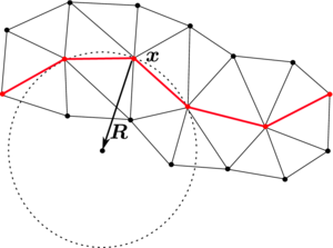
|
| Figure 5: Calculation of the osculating circle at node . |
6.2 Static bubble
We verify our surface tension algorithm with the static bubble test case [37,26]. It consists in a circular fluid bubble into another viscous fluid at rest (see Figure 6), where gravitational or other external forces are neglected. According to the Laplace-Young law, the pressure jump will be , where is the bubble internal pressure, the outer pressure and the bubble radius. Even with non-zero surface tension, the circular shape of the bubble should be preserved and the fluids should remain at rest no matter how long we integrate the equations in time.| Figure 6: Static bubble initial configuration. |
We have simulated the equilibrium state of a circular bubble of a radius (constant curvature ) in a static fluid with , , , and . The simulations have been run 100 time steps with fixed to 0.01. The bubble should remain exactly stationary and the velocity of the fluid should be exactly zero. But if the pressure is approximated continuously, the pressure fluctuations near the interface generate spurious velocity currents (see Figure 7) that may deform the bubble shape, produce a significant mass loss [38] and spoil the solution.
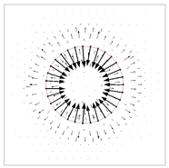
|
| Figure 7: Spurious velocities in static bubble for continuous pressure. |
Figure 8 shows the pressure solution for continuous approximation and different mesh sizes. The exact jump is . We observe that the pressure solution oscillates at the interface, and it improves with finer meshes. In the case of discontinuous pressure approximation shown in Figure 9, the solution is already excellent for coarse meshes. The velocity error (measured in the norm ) for both approximations is shown in Table 1. The discontinuous pressure produces velocity solutions three orders of magnitude better than the continuous one.
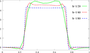
|
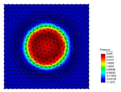
|
| (a) | (b) |
| Figure 8: Continuous pressure approximation: (a) profile at final time for different , and (b) pressure field for . | |
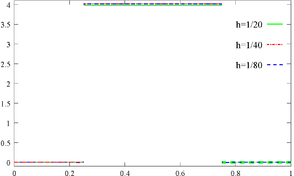
|
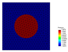
|
| (a) | (b) |
| Figure 9: Discontinuous pressure approximation: (a) profile at final time for different , and (b) pressure field for . | |
| Continuous | Discontinuous | |
| 1/20 | ||
| 1/40 | ||
| 1/80 |
Finally, Figure 10 shows the influence of the parameter on the pressure solution at the interface. For the minimum value that makes the system Eq. (23) invertible, the pressure profile is flat at the interface, i.e. the jump is represented exactly and incompressibility is satisfied. The larger the value of , the more strongly the pressure continuity condition at the interface is imposed.
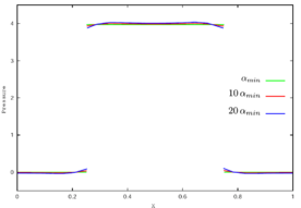
|
| Figure 10: Pressure profile for discontinuous approximation and . Influence of value on the pressure jump at the interface: , , . |
The numerical scheme developed in the previous sections will be tested in the problem of a bubble rising in a liquid column.
7 NUMERICAL EXAMPLE: RISING BUBBLE
Bubbles and bubbly flows play a significant role in a wide range of geophysical and industrial processes, such as mixing in chemical reactors, elaboration of alloys, cooling of nuclear reactors, two-phase heat exchangers, aeration processes, and atmosphere-ocean exchanges.
The shape and rise velocity of a bubble are controlled by the physical properties of the fluids and the surrounding flow field. Grace [39] developed a well-known graphical correlation for single gas bubbles rising in an infinite liquid using three dimensionless numbers: the Reynolds number (), the Eötvös number (), and the Morton number ().
|
where is an equivalent diameter of the bubble, and the rising speed of the bubble. [39] classifies the bubble shapes into three regimes: spherical, ellipsoidal, and spherical cap. Bubbles with low or low are spherical. For higher , bubbles have an ellipsoidal shape at intermediate and spherical cap shape at high . A more detailed regime diagram was given by Clift et al. [40], which included wobbling bubbles for in the ellipsoidal regime, and the spherical cap regime was subdivided into spherical cap, skirted, and dimpled ellipsoidal cap for high, intermediate, and low numbers, respectively. These diagrams were further developed by Bhaga et al. [41], who also studied the flow field around the bubble, specially the wake that forms in the rear of the bubble for intermediate and high .
Numerous experimental studies have been performed to understand the flow dynamics of a single rising bubble, e.g. by [42,39,43,40,41,44,45,46], but the fact that approximate theoretical solutions have only been derived in the limit of very small bubble deformations, together with the difficulties in experimentally measuring the flow variables of the bubble without any interference while it is rising and deforming, make numerical simulation an important tool to gain insight of the flow.
Previous numerical studies have mostly followed the fixed mesh approach: the pioneering works [47], [48], and [49] used the front-tracking method (together with finite differences), also [50] (finite differences) and [51] (finite volume method); level set is used by [27,26,1] (finite elements) and [52] (finite volumes); Volume-of-Fluid is used in [53] and [54]; [55] use a hybrid approach between VOF and level set (finite volumes); and interface fitting method in [56] and [45]. The Lattice-Boltzmann method is used e.g. in [57] and [58]. In these numerical works, results are qualitatively compared with experimental observations of bubble shape under different regimes. Only recently, quantitative tests for two-dimensional rising bubbles have been proposed by Hysing et al. [1]. In Section 7.1 we compare the PFEM results with these test solutions, and in Section 7.2 we propose two problems on bubble breakup and coalescence to assess the ability of a multi-fluid code to model topology changes.
7.1 Comparison with previous numerical experiments
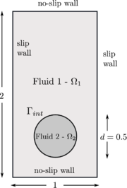
|
| Figure 11: Initial configuration. |
The problem consists in a bubble rising in a liquid column as illustrated in Figure 11. Two tests have been proposed in [1]: test 1 considers a bubble in the ellipsoidal regime which undergoes moderate shape deformation, while in the test 2 the bubble belongs to the skirted regime and experiences much larger deformation. Both fluids are Newtonian, incompressible and isothermal, and their physical properties are listed in Table 2.
| Test case | g | |||||||||
| 1 | 1000 | 100 | 10 | 1 | 0.98 | 24.5 | 35 | 10 | 10 | 10 |
| 2 | 1000 | 1 | 10 | 0.1 | 0.98 | 1.96 | 35 | 125 | 1000 | 100 |
The reference solutions presented in [1] have been run with three different numerical approaches: the TP2D [59], the FreeLIFE [60], and the MooNMD [61]. They all use the finite element method, but the two first approaches describe the interface with the level set, while the latter tracks it in an arbitrary Lagrangian-Eulerian way. More specific details about the methods can be found in the original publication. The following bubble quantities are used to compare the results:
- shape at the final time s,
- circularity ,
- center of mass , and
- rise velocity .
The computations have been performed on unstructured meshes with element size in the bulk of the fluids and wall regions, and the mesh at the interface has been refined to , , and in order to analyze the convergence in of the solution. With a refinement based on the distance to the interface (see Figure 12), we can use an arbitrarily fine mesh without increasing the total number of nodes to impractical values as would be the case with an uniform mesh.
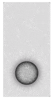
|
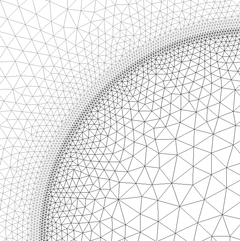
|
| Figure 12: Mesh is refined close to the interface with the help of a distance function. | |
| |||||||||||||||
| Figure 13: Test 1. Bubble evolution for mesh size . |
For test 1, Figure 13 shows the evolution of the rising bubble. At final time s we compare the PFEM bubble shapes for the meshes and , and observe that they converge to the shape of the finest mesh (Figure 14), which is in good agreement with the TP2D solution reported in [1] (Figure 15a). The plots of the bubble circularity (Figure 15b) and rise velocity (Figure 15d) show that our bubble is slightly oscillating, but the evolution of the center of mass (Figure 15c) is again in good agreement. The oscillating behavior of the PFEM results may be explained by the fact that, on the one side, PFEM does not introduce diffusivity at the interface, and on the other side, the geometrical method we use to calculate the curvature (the osculating circle) may not be accurate enough. Regarding the volume conservation, without any correction technique the bubble volume variation between the initial and final times, , is of order (Table 3).
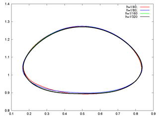
|
| Figure 14: Test 1. PFEM bubble shape for different mesh sizes at s. |
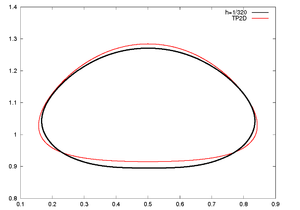
|
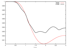
|
| (a) Shape at s | (b) Circularity |
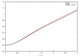
|
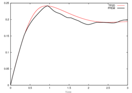
|
| (c) Center of mass | (d) Rise velocity |
| Figure 15: Test 1. Comparison of benchmark quantities: PFEM () vs. TP2D results. | |
| Test | Initial Volume | Final Volume | Variation | |
| 1 | 1/320 | 0.19635 | 0.1965 | |
| 2 | 1/640 | 0.19635 | 0.19633 |
Same type of results are shown for test 2 in Figures 16, 17, and 18. Although the bubbles in both test cases rise with similar velocity, the decrease in surface tension causes bubble 2 to undergo a much larger deformation and to develop thin filaments. In the TP2D and FreeLIFE solutions these filaments break up, in contrast to the moving mesh solutions of PFEM and MooNMD (Figure 18a). In the physical reality, breakup occurs due to capillary waves present on the interface, which trigger the three-dimensional Plateau-Rayleigh instability when the filament radius is small enough. Thus, capillary waves can cause the skirt filament to fragment during flow, though this response requires very large elongations, typically greater than 20 times the initial bubble radius [62]. Figure 19 shows the mesh of the PFEM solution in the skirted region. The filament is not thin enough to break up. The volume variation is excellent again, of order .
| (16) Test 2. Bubble evolution for mesh size . | |||||||||||||||
|
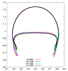
|
| Figure 17: Test 2. PFEM bubble shape for different mesh sizes at s. |
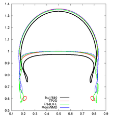
|
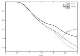
|
| (a) Shape at s | (b) Circularity |
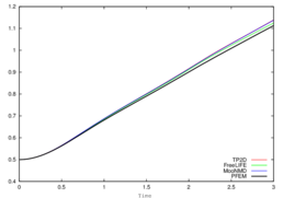
|
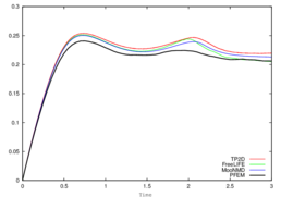
|
| (c) Center of mass | (d) Rise velocity |
| Figure 18: Test 2. Benchmark quantities comparison of PFEM (black line) and TP2D (red), FreeLIFE (green) and MooNMD (blue) results. | |
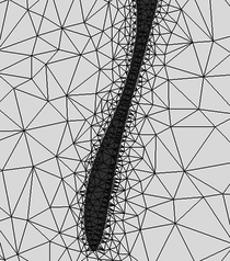
|
| Figure 19: Test 2. Detail of bubble skirt at s. |
The fact of using an explicit approach when discretizing in time the surface tension force introduces the stability condition for the time step expressed in Eq. (24). If larger time steps are taken, instabilities will develop at the interface. This time step constraint is very restrictive for fine meshes (). In our case, the refined mesh close to the interface imposes rather small global time steps (for test 1 with mesh , ; and for test 2 with , ) that undoubtedly affect the computational efficiency.
7.2 Bubble breakup and coalescence
Topology changes in multi-fluid flows can be divided into two classes [63]:
- Films that fragment. If a bubble approaches another bubble or a flat surface, the fluid in between must be squeezed out before the bubbles are sufficiently close so that the film becomes unstable to attractive forces and fragment.
- Threads that break. A long and thin cylinder of fluid will generally break by the Plateau-Rayleigh instability in the region where the cylinder becomes sufficiently thin so that surface tension pinches it into two.
In order to test the capabilities of PFEM to handle interfaces with changing topology, and motivated by the disagreement in the solution of test 2, we have simulated two examples on a film that fragments, namely the breakup and coalescence of bubbles.
We consider the same fluid properties and configuration of test 1. In the case of the breakup, we add a flat interface at so that the upper region belongs to the same fluid than the bubble (see Figure 20a). The bubble rises, approaching the flat interface. The film of heavy fluid that separates the two regions of light fluid becomes thinner and thinner until it fragments and the regions fuse (Figure 20). Whereas in the physical reality the fragmentation of the film is caused by attractive forces at the microscopic scale (forces which are usually not included in the continuum description), in our simulations fragmentation is caused by a connectivity change at the interface, as illustrated in Figure 21.
| ||||||||||||||||
| Figure 20: Bubble breakup. |
One of the main difficulties we face in our Lagrangian approach is the connectivity changes introduced by the remeshing process. In general, these reconnections may alter the equilibrium at the interface, slow down convergence and affect mass conservation. Thus, in interfacial flows it is essential to avoid them. We are using an unconstrained Delaunay triangulator which does not allow to fix connectivities. Therefore, to ensure that a specific connectivity remains, we refine long interfacial edges and remove nodes too close to the interface. Unfortunately, this strategy would preclude the possibility of breakup, as the interface could elongate endlessly. In the way PFEM defines interfaces, it is possible to have fluid regions spanned by just one element layer. The breakup criterium we have implemented in PFEM is to permit connectivity changes in elements where all nodes lie at the interface. In this way, a thin fluid thread can stop elongating and fragment. Breakup is then dependent on the mesh resolution, that is, it happens when the thickness of the film is similar to the mesh resolution of the interface. This is not a drawback specific of PFEM, breakup is mesh dependent in front-capturing methods as well. For example, in the level set method, two interfaces are described as two different zero contours of the same level set function, and these interfaces will automatically merge once they get close enough, relative to the spatial resolution of the mesh where the level set function is defined. The resolution determines the smallest distance between two zero level sets of the level set function for which they can still be distinguished as separate zero contours. Interfaces can in fact merge faster due to the diffusivity of the schemes used for advection and reinitialization of the level set function [27].

|

|
| (a) | (b) |
| Figure 21: Connectivity change that produces breakup at fluid films spanned by just one mesh element. | |
The pressure field at and after breakup is shown in Figures 22 and 23. The different pressure values inside and outside the bubble equilibrate after breakup, what occurs at s.
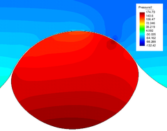
|
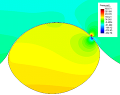
|
| (a) s | (b) s |
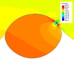
|
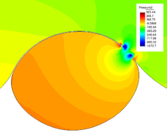
|
| (c) s | (d) s |
| Figure 22: Pressure field at breakup (variable scale ranges in legend). | |
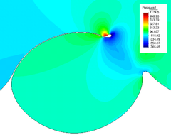
|
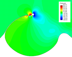
|
| (a) s | (b) s |
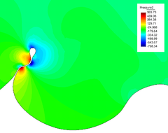
|
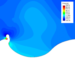
|
| (c) s | (d) s |
| Figure 23: Pressure field after breakup (variable scale ranges in legend). | |
For the simulation of bubble coalescence, we consider the same rectangular domain as before, with two circular bubbles inside. The center of the first bubble is and its radius is equal to 0.25, the center of the second bubble is and the radius 0.2. Since the small bubble is located close to the large one, this lower bubble turns out to be in the wake of the upper bubble and rises faster than that. Figure 24 shows the coalescence process. The mechanism is again the rupture of the thin film between the bubbles. This happens not during the impact of the bubbles (around s) but during the separation after impact, as corresponds to the physical reality [64].
| ||||||||||||||||||||||||
| Figure 24: Bubble coalescence. |
8 SUMMARY AND CONCLUSIONS
We have developed a numerical scheme for the simulation of multi-fluid flows with the Particle Finite Element Method able to deal with large jumps in the physical properties (included surface tension), and able to accurately represent the and discontinuities in the flow variables. Interfaces are tracked by the moving mesh, pressure degrees of freedom have been duplicated at the interface nodes to represent the discontinuity of this variable due to surface tension and variable viscosity (Eq. 9), velocity and pressure variables have been decoupled through a pressure segregation method, and the mesh has been refined in the vicinity of the interface to improve the accuracy and efficiency of the computations.
We have first tested the scheme in a simple static bubble problem and compared the results for continuous and discontinuous pressure approximations. We have then applied the method to the more complicated rising bubble problem presented in Hysing et al. [1]. We can conclude that PFEM solutions for the single rising bubble are in good agreement with those reported in [1]. For test 1, our bubble is slightly oscillating in contrast to the reference solution. A reason for this may be that PFEM does not introduce diffusion at the interface. In any case, more comparisons with other methods are needed. For test 2, although PFEM can handle interface breakup without problems (as shown in Section 7.2), the skirt filaments remain intact. Breakup happens only when the fluid region is spanned by just one element layer. This allows to model thin films of thickness , being the mesh size at the interface. In both tests, we have achieved an excellent mass conservation without any correction.
Finally, we propose two bubble breakup and coalescence problems as benchmarks for testing the capabilities of multi-fluid flow codes to handle topology changes of the interface.
BIBLIOGRAPHY
[1] Hysing, S. and Turek, S. and D. Kuzmin and N. Parolini and E. Burman and S. Ganesan and L. Tobiska. (2009) "Quantitative benchmark computations of two-dimensional bubble dynamics", Volume 60. International Journal for Numerical Methods in Fluids 1259-1288
[2] Idelsohn, S.R. and Mier-Torrecilla, M. and Oñate, E. (2009) "Multi-fluid flows with the Particle Finite Element Method", Volume 198. Computer Methods in Applied Mechanics and Engineering 2750-2767
[3] G.K. Batchelor. (1967) "An introduction to fluid dynamics". Cambridge University Press
[4] Idelsohn, S.R. and Mier-Torrecilla, M. and Nigro, N. and Oñate, E. (2009) "On the analysis of heterogeneous fluids with jumps in the viscosity using a discontinuous pressure field", Volume In press. Computational Mechanics
[5] Unverdi, S.O. and Tryggvason, G. (1992) "Computations of multi-fluid flows", Volume 60. Physica D: Nonlinear Phenomena 70-83
[6] W. Shyy. (1996) "Computational Fluid Dynamics with moving boundaries". Taylor&Francis
[7] Scardovelli, R. and Zaleski, S. (1999) "Direct Numerical Simulation of free-surface and interfacial flow", Volume 31. Annual Reviews of Fluid Mechanics 567-603
[8] Caboussat, A. (2005) "Numerical simulation of two-phase free surface flows", Volume 12. Archives of Computational Methods in Engineering 165-224
[9] Hughes, T.J.R. and Liu, W.K. and Zimmermann, T.K. (1981) "Lagrangian-Eulerian finite element element formulation for incompressible viscous flows", Volume 29. Computer Methods in Applied Mechanics and Engineering 239-349
[10] B. Ramaswamy and M. Kawahara. (1986) "Arbitrary Lagrangian-Eulerian finite element method for the analysis of free surface fluid flows", Volume 1. Computational Mechanics 103-108
[11] T.E. Tezduyar and M. Behr and J. Liou. (1992) "A new strategy for finite element computations involving moving boundaries and interfaces. The deforming-spatial-domain/space-time procedure: I. The concept and preliminary numerical tests", Volume 94. Computer Methods in Applied Mechanics and Engineering 339-351
[12] T.E. Tezduyar and M. Behr and S. Mittal and J. Liou. (1992) "A new strategy for finite element computations involving moving boundaries and interfaces. The deforming-spatial-domain/space-time procedure: II. Computation of free-surface flows, two-liquid flows and flows with drifting cylinders", Volume 94. Computer Methods in Applied Mechanics and Engineering 353-371
[13] Hirt, C.W. and Cook, J.L. and Butler, T.D. (1970) "A Lagrangian method for calculating the dynamics of an incompressible fluid with free surface", Volume 5. Journal of Computational Physics 103-124
[14] B. Ramaswamy and M. Kawahara. (1987) "Lagrangian finite element analysis applied to viscous free surface fluid flow", Volume 7. International Journal for Numerical Methods in Fluids 953-984
[15] Idelsohn, S.R. and Oñate, E. and Del Pin, F. (2003) "A Lagrangian meshless finite element method applied to fluid-structure interaction problems", Volume 81. Computers and Structures 8–11 655–671
[16] Idelsohn, S.R. and Oñate, E. and Del Pin, F. (2004) "The Particle Finite Element Method: A powerful tool to solve incompressible flows with free-surfaces and breaking waves", Volume 61. International Journal for Numerical Methods in Engineering 7 964–989
[17] Oñate, E. and Idelsohn, S.R. and Del Pin, F. and Aubry, R. (2004) "The Particle Finite Element Method: An Overview", Volume 1. International Journal of Computational Methods 2 267–307
[18] Del Pin, F. and Idelsohn, S.R. and Oñate, E. and Aubry, R. (2007) "The ALE/Lagrangian Particle Finite Element Method: A new approach to computation of free-surfaces flows and fluid-object interactions", Volume 36. Computers and Fluids 1 27–38
[19] Harlow, F.H. (1964) "The Particle-in-Cell computing method for fluid dynamics", Volume 3. Methods in Computational Physics 313-343
[20] Unverdi, S.O. and Tryggvason, G. (1992) "A front-tracking method for viscous, incompressible, multi-fluid flows", Volume 100. Journal of Computational Physics 25-37
[21] Hirt, C. and Nichols, B. (1981) "Volume of Fluid (VOF) method for the dynamics of free boundaries", Volume 39. Journal of Computational Physics 201-225
[22] Osher, S. and Sethian, J. (1988) "Fronts propagating with curvature dependant speed: algorithms based on Hamilton-Jacobi formulations", Volume 79. Journal of Computational Physics 12-49
[23] Idelsohn, S.R. and Calvo, N. and Oñate, E. (2003) "Polyhedrization of an arbitrary 3D point set", Volume 192. Computer Methods in Applied Mechanics and Engineering 2649-2667
[24] Oñate, E. and Idelsohn, S.R. and Celigueta, M.A. and Rossi, R. (2008) "Advances in the Particle Finite Element Method for the analysis of fluid-multibody interaction and bed erosion in free surface flows", Volume 197. Computer Methods in Applied Mechanics and Engineering 1777-1800
[25] van Kan, J. (1986) "A second-order accurate pressure correction scheme for viscous incompressible flow", Volume 7. SIAM Journal on Scientific and Statistical Computing 870-891
[26] A. Smolianski. (2001) "Numerical Modeling of Two Fluid Interfacial Flows". University of Jyväskylä
[27] A.-K. Tornberg. (2000) "Interface Tracking Methods with Application to Multiphase Flows". Royal Institute of Technology, Stockholm
[28] Minev, P.D. and Chen, T. and Nandakumar, K. (2003) "A finite element technique for multifluid incompressible flow using Eulerian grids", Volume 187. Journal of Computational Physics 255-273
[29] Coppola-Owen, A.H. and Codina, R. (2005) "Improving Eulerian two-phase flow finite element approximation with discontinuous gradient pressure shape functions", Volume 49. International Journal for Numerical Methods in Fluids 1287-1304
[30] J. Chessa and T. Belytschko. (2003) "An extended finite element method for two-phase fluids", Volume 70. ASME Journal of Applied Mechanics 10-17
[31] S. Gross and A. Reusken. (2007) "An extended pressure finite element space for two-phase incompressible flows with surface tension", Volume 224. Journal of Computational Physics 40-58
[32] Juntunen, M. and Stenberg, R. (2007) "Nitsche's method for general boundary conditions". Research Reports A530, University of Technology, Institute of Mathematics
[33] Mier-Torrecilla, M. (2010) "Numerical simulation of multi-fluid flows with the Particle Finite Element Method". Technical University of Catalonia
[34] J.U. Brackbill and D.B. Kothe and C. Zemach. (1992) "A continuum method for modeling surface tension", Volume 100. Journal of Computational Physics 335-354
[35] Bänsch, E. (2001) "Finite Element discretization of the Navier-Stokes equations with a free capillary surface", Volume 88. Numerische Mathematik 203-235
[36] Hysing, S. (2006) "A new implicit surface tension implementation for interfacial flows", Volume 51. International Journal for Numerical Methods in Fluids 659-672
[37] Popinet, S. and Zaleski, S. (1999) "A front tracking algorithm for accurate representation of surface tension", Volume 30. International Journal for Numerical Methods in Fluids 775-793
[38] Sussman, M. and Smereka, P. and Osher, S. (1994) "A level set approach for computing solutions to incompressible two-phase flows", Volume 114. Journal of Computational Physics 146-159
[39] Grace, J. R. (1973) "Shapes and Velocities of Bubbles Rising in Infinite Liquids", Volume 51. Transactions of the Institution of Chemical Engineers 116-120
[40] R. Clift and J.R. Grace and M.E. Weber. (1978) "Bubbles, drops and particles". Academic Press
[41] Bhaga, D. and Weber, M.E. (1981) "Bubbles in viscous liquids: shapes, wakes and velocities", Volume 105. Journal of Fluid Mechanics 61-85
[42] Haberman, W. L. and Morton, R. K. (1954) "An experimental study of bubbles moving in liquids", Volume 387. Proceedings of the American Society of Civil Engineers 1-25
[43] Hnat, J. G. and Buckmaster, J. D. (1976) "Spherical cap bubbles and skirt formation", Volume 19. Physics of Fluids 182-194
[44] Maxworthy, T. and Gnann, C. and Kuerten, M. and Durst, F. (1996) "Experiments on the rise of air bubbles in clean viscous liquids", Volume 321. Journal of Fluid Mechanics 421-441
[45] F. Raymond and J.M. Rosant. (2000) "A numerical and experimental study of the terminal velocity and shape of bubbles in viscous liquids", Volume 55. Chemical Engineering Science 943-955
[46] M. Wu and M. Gharib. (2002) "Experimental Studies on the Shape and Path of Small Air Bubbles Rising in Clean Water", Volume 14. Physics of Fluids 49-52
[47] Esmaeeli, A. and Tryggvason, G. (1998) "Direct numerical simulations of bubbly flows. Part 1. Low Reynolds number arrays", Volume 377. Journal of Fluid Mechanics 313-345
[48] Esmaeeli, A. and Tryggvason, G. (1999) "Direct numerical simulations of bubbly flows. Part 2. Moderate Reynolds number arrays", Volume 385. Journal of Fluid Mechanics 325-358
[49] Bunner, B. and Tryggvason, G. (2002) "Dynamics of homogeneous bubbly flows. Part 1. Rise velocity and microstructure of the bubbles", Volume 466. Journal of Fluid Mechanics 17-52
[50] F.S. de Sousa and N. Mangiavacchi and L.G. Nonato and A. Castelo and M.F. Tomé and V.G. Ferreira and J.A. Cuminato and S. McKee. (2004) "A front-tracking/front-capturing method for the simulation of 3D multi-fluid flows with free surfaces", Volume 198. Journal of Computational Physics 469-499
[51] Hua, J. and Lou, J. (2007) "Numerical simulation of bubble rising in viscous liquid", Volume 222. Journal of Computational Physics 769-795
[52] Z. Yu and L.-S. Fan. (2008) "Direct Simulation of the Buoyant Rise of Bubbles in Infinite Liquid Using Level Set Method", Volume 86. Canadian Journal of Chemical Engineering 267-275
[53] L. Chen and S.V. Garimella and J.A. Reizes and E. Leonardi. (1999) "The development of a bubble rising in a viscous liquid", Volume 387. Journal of Fluid Mechanics 61-96
[54] Van Sint Annaland, M. and N. G. Deen and J. A. M. Kuipers. (2005) "Numerical Simulation of Gas Bubbles Behavior Using a Three-Dimensional Volume of Fluid Method", Volume 60. Chemical Engineering Science 2999-3011
[55] Bonometti, T. and Magnaudet, J. (2007) "An interface-capturing method for incompressible two-phase flows. Validation and application to bubble dynamics", Volume 33. International Journal of Multiphase Flow 109-133
[56] Ryskin, G. and Leal, L. G. (1984) "Numerical solution of free-boundary problems in fluid mechanics. Part 2. Buoyancy-driven motion of a gas bubble through a quiescent liquid", Volume 148. Journal of Fluid Mechanics 19-35
[57] X. Frank and D. Funfschilling and N. Midoux and H. Z. Li. (2006) "Bubbles in a viscous liquid: Lattice Boltzmann simulation and experimental validation", Volume 546. Journal of Fluid Mechanics 113-122
[58] I. O. Kurtoglu and C. L. Lin. (2006) "Lattice Boltzmann Study of Bubble Dynamics", Volume 50. Numerical Heat Transfer B 333-351
[59] S. Turek. (1998) "Efficient Solvers for Incompressible Flow Problems". Springer
[60] Parolini, N. and Burman, E. (2005) "A finite element level set method for viscous free-surface flows". 7th Conference on Applied and Industrial Mathematics in Italy 416-427
[61] Ganesan, S. and Matthies, G. and Tobiska, L. (2007) "On spurious velocities in incompressible flow problem with interfaces", Volume 196. Computer Methods in Applied Mechanics and Engineering 1193-1202
[62] Stone, H. (1994) "Dynamics of drop deformation and breakup in viscous fluids", Volume 26. Annual Reviews of Fluid Mechanics 65-102
[63] Tryggvason, G. and Bunner, B. and Esmaeeli, A. and Juric, D. and Al-Rawahi, N. and Tauber, W. and Han, J. and Nas, S. and Jan, Y.-J. (2001) "A front-tracking method for the computations of multiphase flow", Volume 169. Journal of Computational Physics 708-759
[64] N. Bremond and A. Thiam and J. Bibette. (2008) "Decompressing Emulsion Droplets Favors Coalescence", Volume 100. Physical Review Letters
Document information
Published on 01/01/2010
Licence: CC BY-NC-SA license
Share this document
Keywords
claim authorship
Are you one of the authors of this document?
