| (18 intermediate revisions by the same user not shown) | |||
| Line 1: | Line 1: | ||
| − | + | Published in ''Recent Advances in Textile Membranes and Inflatable Structures'', Springer Verlag, pp. 241 - 257, 2005<br /> | |
| + | DOI: 10.1007/1-4020-3317-6_15 | ||
| + | |||
| Line 129: | Line 131: | ||
==3 Structural Analysis and Pattern Design== | ==3 Structural Analysis and Pattern Design== | ||
| − | Traditional methods for analysis of inflatable structure are based on membrane and tube theories <span id='citeF-9'><span id='citeF-10'>[[#cite-9|[9]], [[#cite-10|10]]]. A more detailed analysis of inflatable structures can be performed using membrane finite elements allowing for large displacement | + | Traditional methods for analysis of inflatable structure are based on membrane and tube theories <span id='citeF-9'><span id='citeF-10'>[[#cite-9|[9]], [[#cite-10|10]]]. A more detailed analysis of inflatable structures can be performed using membrane finite elements allowing for large displacement analysis combined with one-dimensional elements to model the tension ropes, if necessary. The membrane formulation used is an extension of the rotation-free shell finite element formulation developed by the authors in recent years <span id='citeF-11'><span id='citeF-12'><span id='citeF-13><span id='citeF-14'><span id='citeF-15'>[[#cite-11|[11]]-[[#cite-15|15]]]. The following analysis conditions are typically considered. |
| − | * Coupled aerodynamic analysis in order to compute the evolution of the shape of the structure under different wind conditions. Aerodynamic load are also essential to design the anchoring system. The fluid-dynamic | + | * Coupled aerodynamic analysis in order to compute the evolution of the shape of the structure under different wind conditions. Aerodynamic load are also essential to design the anchoring system. The fluid-dynamic analysis is based in the stabilized finite element method developed by the authors <span id='citeF-16'>[[#cite-16|[16]]]. The coupled fluid-structure interaction formulation used is an extension of that derived by the authors for ship hydrodynamic analysis <span id='citeF-17'>[[#cite-17|[17]]]. |
| − | * Thermal analysis in order to study the evolution of temperature in the | + | * Thermal analysis in order to study the evolution of temperature in the textile material under prescribed external temperature changes. The thermal analysis can be complemented by the computation of the temperature evolution in the interior of the structure using the finite element method. |
<div id='img-6'></div> | <div id='img-6'></div> | ||
| Line 143: | Line 145: | ||
|} | |} | ||
| − | The accurate pattern design is essential to ensure the correct shape of the | + | The accurate pattern design is essential to ensure the correct shape of the structure after the inflating process. The pattern design procedure developed by the authors is based on the isoparametric finite element concept. Patterns are assimilated to finite element patches and are defined using the prepost processing system GiD developed at CIMNE <span id='citeF-18'>[[#cite-18|[18]]]. A mapping into the isoparametric space allows representing the pattern geometry in a 2D system, thus providing the necessary information for the cutting machine using a standard plotting system (Fig. [[#img-7|7]]). Fig. [[#img-8|8]] shows a scale model in paper used to verify the pattern design of the ECCOMAS 2000 inflatable pavilion formed by low pressure tubes. |
<div id='img-7'></div> | <div id='img-7'></div> | ||
{| class="floating_imageSCP" style="text-align: center; border: 1px solid #BBB; margin: 1em auto; width: 100%;max-width: 100%;" | {| class="floating_imageSCP" style="text-align: center; border: 1px solid #BBB; margin: 1em auto; width: 100%;max-width: 100%;" | ||
|- | |- | ||
| − | |[[Image:Draft_Samper_233606860-Fig7.png| | + | |[[Image:Draft_Samper_233606860-Fig7.png|300px|Plotter system used to cut the membrane patches]] |
|- style="text-align: center; font-size: 75%;" | |- style="text-align: center; font-size: 75%;" | ||
| colspan="1" | '''Figure 7:''' Plotter system used to cut the membrane patches | | colspan="1" | '''Figure 7:''' Plotter system used to cut the membrane patches | ||
| Line 165: | Line 167: | ||
The use of structures formed by low pressure inflatable tubes is ideal to cover large temporal spaces. Innovative design allows offering clients unique products. | The use of structures formed by low pressure inflatable tubes is ideal to cover large temporal spaces. Innovative design allows offering clients unique products. | ||
| − | The exclusive and never seen design generates a great distinct impact for the users of inflatable system. The systems is ideal for applications that require | + | The exclusive and never seen design generates a great distinct impact for the users of inflatable system. The systems is ideal for applications that require temporal covers and pavilions with an exclusive design as a differentiation aspect. Effectiveness and easy assembly are the main aspects to be considered. The design possibilities that the system allow are really enormous, offering to the client covers with a great personalised and refined design value. |
<div id='img-9'></div> | <div id='img-9'></div> | ||
| Line 179: | Line 181: | ||
New requirements have been identified and different solutions were developed in order to increase the possibilities of low pressure inflatable structures to success into the civil engineering and architecture market. | New requirements have been identified and different solutions were developed in order to increase the possibilities of low pressure inflatable structures to success into the civil engineering and architecture market. | ||
| − | Some of the aspects developed by the authors in order to increase the use of | + | Some of the aspects developed by the authors in order to increase the use of inflatable structures and to construct a new generation of inflatable covers for civil and architectural applications are: |
| − | * Regarding the manufacturing aspect, the development and | + | * Regarding the manufacturing aspect, the development and optimisation of the procedures aiming to change from a non-industrial construction process to knowledge based industrial process using latest Information Technologies (IT) tools. An important objective was the reduction of production costs in order to make inflatable structures more competitive versus other temporary cover systems |
* This requires multidisciplinary studies of the production chain, such as new lighter and cheaper materials and the optimisation of the production process. | * This requires multidisciplinary studies of the production chain, such as new lighter and cheaper materials and the optimisation of the production process. | ||
| − | * Much effort was dedicated to the pattern generation and | + | * Much effort was dedicated to the pattern generation and optimisation in order to reduce material lost and makes the material work in a better way. New software to generate and optimise patterns was developed considering new material properties (anisotropy, multi layers, real shape of the fabrics, etc.) |
| − | * Alternative energy supplies and new ways to inflate the covers were developed to ensure the use of inflatable solutions in | + | * Alternative energy supplies and new ways to inflate the covers were developed to ensure the use of inflatable solutions in marginal or disaster areas. It was important to optimise the use of gas (air or helium) inside the structure in order to minimise fluid lost. |
| − | * Material and mechanical behaviour of inflated structures follow different design principles from those typically used in standard concrete, steel or aluminium structures. Hence new conceptual and manufacturing concepts were developed in order to satisfy the | + | * Material and mechanical behaviour of inflated structures follow different design principles from those typically used in standard concrete, steel or aluminium structures. Hence new conceptual and manufacturing concepts were developed in order to satisfy the increasing market demands while preserving necessary safety, comfort and operational requirements. Structural control for wind pressure and temperature loads was mandatory in these cases. |
The security of inflatable buildings was kept in mind in the implementation of every development. | The security of inflatable buildings was kept in mind in the implementation of every development. | ||
| Line 193: | Line 195: | ||
===6.1 ECCOMAS 2000 Pavilion=== | ===6.1 ECCOMAS 2000 Pavilion=== | ||
| − | An inflatable structure formed by 11 low pressure tubes was designed and built as the Pavilion of the International Center for Numerical Methods in Engineering (CIMNE) at the ECCOMAS Congress held in Barcelona on 11-15 September 2000 [ | + | An inflatable structure formed by 11 low pressure tubes was designed and built as the Pavilion of the International Center for Numerical Methods in Engineering (CIMNE) at the ECCOMAS Congress held in Barcelona on 11-15 September 2000 <span id='citeF-19'>[[#cite-19|[19]]]. The construction required 500 m<math display="inline">^2</math> of Polyamide 6.6 material and some 1000 meters of sewing. Figs. [[#img-10|[10]]-[[#img-11|11]]] show a plant of the inflatable pavilion and a view of the exterior and interior during the exhibition. |
<div id='img-10'></div> | <div id='img-10'></div> | ||
| Line 207: | Line 209: | ||
|- | |- | ||
|[[Image:Draft_Samper_233606860-Fig11a.png|351px|]] | |[[Image:Draft_Samper_233606860-Fig11a.png|351px|]] | ||
| + | |- | ||
|[[Image:Draft_Samper_233606860-Fig11b.png|351px|Exterior and interior views of the ECCOMAS 2000 inflatable pavilion]] | |[[Image:Draft_Samper_233606860-Fig11b.png|351px|Exterior and interior views of the ECCOMAS 2000 inflatable pavilion]] | ||
|- style="text-align: center; font-size: 75%;" | |- style="text-align: center; font-size: 75%;" | ||
| Line 214: | Line 217: | ||
===6.2 Gaudi Institute Exhibition Pavilion=== | ===6.2 Gaudi Institute Exhibition Pavilion=== | ||
| − | An inflatable pavilion has been recently built by the company BuildAir in | + | An inflatable pavilion has been recently built by the company BuildAir in cooperation with the authors for the Gaudi Institute of Barcelona for a mobile exhibition on Construction Artisans. |
===Architectural design and concepts=== | ===Architectural design and concepts=== | ||
| Line 221: | Line 224: | ||
{| class="floating_imageSCP" style="text-align: center; border: 1px solid #BBB; margin: 1em auto; width: 100%;max-width: 100%;" | {| class="floating_imageSCP" style="text-align: center; border: 1px solid #BBB; margin: 1em auto; width: 100%;max-width: 100%;" | ||
|- | |- | ||
| − | |[[Image:Draft_Samper_233606860-Fig12.png| | + | |[[Image:Draft_Samper_233606860-Fig12.png|451px|Architectural concepts as basis of the Gaudi pavilion design]] |
|- style="text-align: center; font-size: 75%;" | |- style="text-align: center; font-size: 75%;" | ||
| colspan="1" | '''Figure 12:''' Architectural concepts as basis of the Gaudi pavilion design | | colspan="1" | '''Figure 12:''' Architectural concepts as basis of the Gaudi pavilion design | ||
|} | |} | ||
| − | The construction technique was based on the low pressure tube technology | + | The construction technique was based on the low pressure tube technology described. A total of 58 tubes were used to cover a surface of 250m<math display="inline">^2</math>. A plan of the structure and different views of the inflated pavilion reaching height of 8.50 mts are shown in Figs. [[#img-13|[13]]-[[#img-15|15]]]. |
<div id='img-13'></div> | <div id='img-13'></div> | ||
{| class="floating_imageSCP" style="text-align: center; border: 1px solid #BBB; margin: 1em auto; width: 100%;max-width: 100%;" | {| class="floating_imageSCP" style="text-align: center; border: 1px solid #BBB; margin: 1em auto; width: 100%;max-width: 100%;" | ||
|- | |- | ||
| − | |[[Image:Draft_Samper_233606860-Fig13.png| | + | |[[Image:Draft_Samper_233606860-Fig13.png|451px|Plan view of the inflatable pavilion for the Gaudi Institute Exhibition using 58 low pressure tubes]] |
|- style="text-align: center; font-size: 75%;" | |- style="text-align: center; font-size: 75%;" | ||
| colspan="1" | '''Figure 13:''' Plan view of the inflatable pavilion for the Gaudi Institute Exhibition using 58 low pressure tubes | | colspan="1" | '''Figure 13:''' Plan view of the inflatable pavilion for the Gaudi Institute Exhibition using 58 low pressure tubes | ||
| Line 239: | Line 242: | ||
{| class="floating_imageSCP" style="text-align: center; border: 1px solid #BBB; margin: 1em auto; width: 100%;max-width: 100%;" | {| class="floating_imageSCP" style="text-align: center; border: 1px solid #BBB; margin: 1em auto; width: 100%;max-width: 100%;" | ||
|- | |- | ||
| − | |[[Image:Draft_Samper_233606860-Fig14.png| | + | |[[Image:Draft_Samper_233606860-Fig14.png|451px|Interior view of the inflated Gaudi Institute Exhibition pavilion]] |
|- style="text-align: center; font-size: 75%;" | |- style="text-align: center; font-size: 75%;" | ||
| colspan="1" | '''Figure 14:''' Interior view of the inflated Gaudi Institute Exhibition pavilion | | colspan="1" | '''Figure 14:''' Interior view of the inflated Gaudi Institute Exhibition pavilion | ||
| Line 247: | Line 250: | ||
{| class="floating_imageSCP" style="text-align: center; border: 1px solid #BBB; margin: 1em auto; width: 100%;max-width: 100%;" | {| class="floating_imageSCP" style="text-align: center; border: 1px solid #BBB; margin: 1em auto; width: 100%;max-width: 100%;" | ||
|- | |- | ||
| − | |[[Image:Draft_Samper_233606860-Fig15.png| | + | |[[Image:Draft_Samper_233606860-Fig15.png|451px|Front view of the inflated Gaudi Institute Exhibition pavilion]] |
|- style="text-align: center; font-size: 75%;" | |- style="text-align: center; font-size: 75%;" | ||
| colspan="1" | '''Figure 15:''' Front view of the inflated Gaudi Institute Exhibition pavilion | | colspan="1" | '''Figure 15:''' Front view of the inflated Gaudi Institute Exhibition pavilion | ||
| Line 254: | Line 257: | ||
===Public Engineering Constructions exhibition=== | ===Public Engineering Constructions exhibition=== | ||
| − | This is another example of applications of inflatable pavilions to generate | + | This is another example of applications of inflatable pavilions to generate temporal spaces for itinerant exhibitions. In this case, Buildair in cooperation with the authors had designed and constructed a space of 1.200 m<math display="inline">^2</math> formed by an array of 6 pavilions of 11 meters by 16 meters. |
<div id='img-16'></div> | <div id='img-16'></div> | ||
{| class="floating_imageSCP" style="text-align: center; border: 1px solid #BBB; margin: 1em auto; width: 100%;max-width: 100%;" | {| class="floating_imageSCP" style="text-align: center; border: 1px solid #BBB; margin: 1em auto; width: 100%;max-width: 100%;" | ||
|- | |- | ||
| − | |[[Image:Draft_Samper_233606860-Fig16.png| | + | |[[Image:Draft_Samper_233606860-Fig16.png|451px|External view of inflatable pavilions, Francia Train Station. Barcelona, diciembre 2003]] |
|- style="text-align: center; font-size: 75%;" | |- style="text-align: center; font-size: 75%;" | ||
| colspan="1" | '''Figure 16:''' External view of inflatable pavilions, Francia Train Station. Barcelona, diciembre 2003 | | colspan="1" | '''Figure 16:''' External view of inflatable pavilions, Francia Train Station. Barcelona, diciembre 2003 | ||
| Line 269: | Line 272: | ||
{| class="floating_imageSCP" style="text-align: center; border: 1px solid #BBB; margin: 1em auto; width: 100%;max-width: 100%;" | {| class="floating_imageSCP" style="text-align: center; border: 1px solid #BBB; margin: 1em auto; width: 100%;max-width: 100%;" | ||
|- | |- | ||
| − | |[[Image:Draft_Samper_233606860-Fig17.png| | + | |[[Image:Draft_Samper_233606860-Fig17.png|451px|Interior view of the pavilion]] |
|- style="text-align: center; font-size: 75%;" | |- style="text-align: center; font-size: 75%;" | ||
| colspan="1" | '''Figure 17:''' Interior view of the pavilion | | colspan="1" | '''Figure 17:''' Interior view of the pavilion | ||
| Line 277: | Line 280: | ||
{| class="floating_imageSCP" style="text-align: center; border: 1px solid #BBB; margin: 1em auto; width: 100%;max-width: 100%;" | {| class="floating_imageSCP" style="text-align: center; border: 1px solid #BBB; margin: 1em auto; width: 100%;max-width: 100%;" | ||
|- | |- | ||
| − | |[[Image:Draft_Samper_233606860-Fig18.png| | + | |[[Image:Draft_Samper_233606860-Fig18.png|451px|Door detail, formed by an inflatable ball]] |
|- style="text-align: center; font-size: 75%;" | |- style="text-align: center; font-size: 75%;" | ||
| colspan="1" | '''Figure 18:''' Door detail, formed by an inflatable ball | | colspan="1" | '''Figure 18:''' Door detail, formed by an inflatable ball | ||
| Line 291: | Line 294: | ||
<div id="cite-3"></div> | <div id="cite-3"></div> | ||
| − | [[#citeF-3| | + | [[#citeF-3|3]] Rehmet M, Bauder C, Schäfer, I Kröplin BH (1994) Solar Powered Airship Project. International Conference Remotely Piloted Vehicles, Bristol |
<div id="cite-4"></div> | <div id="cite-4"></div> | ||
Latest revision as of 10:40, 14 June 2019
Published in Recent Advances in Textile Membranes and Inflatable Structures, Springer Verlag, pp. 241 - 257, 2005
DOI: 10.1007/1-4020-3317-6_15
Keywords Inflatable structures, membrane simulation codes, temporal pavilions, inflatable structures for civil applications
1 Introduction
Inflatable structures have become increasingly popular in recent years for a wide range of applications in architecture, civil engineering, aeronautic (airships) and airspace situations [1-5].
Inflatable structures have unique features. Because of their foldability and air or helium pneumatic stabilisation they cannot be compared to any classical structural concepts.
The use of inflatable structures can be found in temporary and/or foldable structures to cover large spaces or to support other elements, in permanent roofs or shelters with a high degree of transparency, in mobile buildings as temporary housing in civil logistic missions (e.g. environmental disasters and rescue situations), in the construction of tunnels and dams, in antennas for both ground and aerospace applications, as well as in extremely light airship structures among other uses.
Space Applications
Inflatable structures for space applications can be classified into two categories. The first one corresponds with satellite appendages and the second one with habitats.
Inflatable structures in satellite appendages can be the primary structure of the appendage, or else be used as the deployment mechanism itself. In the first case the inflatable structure should become rigid after inflated. For deployment mechanisms the integrity of the inflatable structure is not requested after deployment and its rigidity is obtained by means of other structural members assembled during deployment.
Examples of typical satellite appendages where the inflated technology is applicable include solar arrays and flat antenna arrays among others. A flat sunshield concept with inflated struts which become rigid after inflated has been recently developed by EADS CASA Space in the context of the INFLAST project of the Growth EC programme carried out in cooperation with the authors [6].
Inflatable habitats, on the other hand, are characterized by a big inflated volume. These habitats can be used for space stations or Moon/Mars missions [7-8]. Other applications include the protection of rovers or other instruments in airspace vehicles or stations. Indeed, inflatable habitats request structures that can with-stand loads such as micrometeorites impacts and radiations.
Civil applications
Inflated structures for civil applications are competitive due to their minimum weight, high foldability, easy assembly and disassembly as well as easy and quick transportation with little manpower and maintenance.
For civil applications, different efforts have been made in the past years to develop inflated structures formed by assembly of high or low pressure tubes. This effort has increased the penetration of inflatable buildings in the market, but the growth on the use of this structural type is still very low.
Recent applications of inflated roof structures include air supported halls for sport or exhibition events with a low internal pressure. In the USA areas up to 30000 m2 have been covered with air supported membrane structures [i1]. Their disadvantage is the high energy consumption to keep the pressure permanent in the total inner volume. For structures with high pressure (higher than 1,0 kN/m2) the use of inflated elements has often been proposed, but they have rarely been built (Fuji-Pavillon, Japan). The reasons are that the necessary materials, structural design and manufacturing techniques have not been fully developed [i2]. Double layer membrane structures, usually known as inflated cushions, require rigid elements at the edges or compression rings. They are used instead of glass elements due to their lower price, which is 1/3 of a glass covering. So far there are only two German companies dealing with these inflated cushions in the world market.
Generic technologies have already been tested on prototypes such as a hangar [i3], exhibition hall [i4, i5], various tube structures [i6] and an airship [i7]. A supporting structure for an exhibition hall was built out of high pressure inflated chambers by FESTO in 1996. The structure has many new features. These include the use of double-layer-fabric for the walls as load bearing elements, flame-inhibiting elastomer coatings and a new translucent ethylene-vinyl-acetate coating as well as the active control of the structure against wind load. [i4,i5] References to structures filled with lighter-than-air gas i.e. helium, using the buoyancy forces to stabilize the structures, cannot be found in the literature. A structure of this type has been designed and built as helium filled hangar and as an air supported exhibition pavilion [i3, i6].
The knowledge needed to improve the inflatable construction system, the inexistence of tools for computer aided design and specifications makes difficult that professionals who design temporal and mobile structures choose the inflatable solution.
This article describes the experience of the authors in the design, analysis and construction of inflatable structures for civil applications using an assembly of low pressure elements such as tubes and double layer membranes with tension ropes.
The basis of this technology was developed by the authors in the INFLAST project [6] completed in October 2000 [Brite Euram Project Nr. BE96-3015 “New methodology for Design and Manufacturing of Inflated Structures” (INFLAST)]. This technology has been applied to the design and construction of a number of inflated structures.
2 Inflatable Structures
An inflatable structure is composed by an exterior flexible membrane that contains a fluid inside (in general air or helium). The function of the interior fluid is to maintain the exterior membrane under strength. Final shape of the inflatable structure and its structural resistance depends on the strength of the external membrane and the pattern design. The strength of the external membrane is directly related to the pressure of the air contained inside the structure and the volume between external membranes.
The commercial scope of inflatable products ranges from those which are available on the market for example, inflatable boats, lifecrafts, escape slides, mattresses, toys and containers to others that are relatively new as airbags and special membrane structures
2.1 High Pressure Inflatable Structures
Some efforts have been made in the past years to develop inflated structures formed by assembly of high pressure tubes.
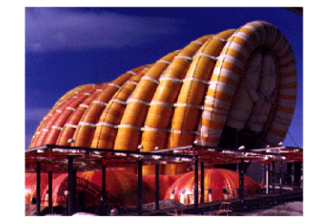
The obvious disadvantages of these structures are the design of the joints and their big vulnerability to air losses. In general, high pressure inflated structures are difficult to maintain and repair and have a high cost. An example of inflated pavilions formed by high pressure tubes is shown in Fig. 1.
|
| Figure 1: Example of inflated pavilion formed by assembly of high pressure tubes. “Fuji” Inflatable pavilion constructed by Mamoru Kawaguchi in 1974 for the “Expo Tokyo” |
2.2 Low Pressure Inflatable Structures
Inflatable structures formed by an assembly of self-supported low pressure membrane elements are ideal to cover large space areas. They also adapt easily to any design shape and have minimal maintenance requirements, other than keeping a constant low internal pressure accounting for the air losses through the material pores and the seams.
Air supported system
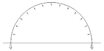
One of the inflatable systems most commonly used is in the so called “air supported system”. In this structural case an inner space is generated from a completely closed membrane perimeter and filled with air at low pressure.
|
| Figure 2: Functional schema of the “Air supported system” |
There are areas of more than 30.000 m2 covered with this kind of structures. In any case, this system has several disadvantages:
- Excessive air volume is needed to support the cover.
- Complex access should be designed to ensure the stagnation of the inner space.
- Anchoring loads are really high in order to support the strength of the exterior membrane.
- Thermal resistance is very low. This aspect has a strong incidence in the climatization of the inner space.
- Because of the contact or cold membrane with inner hot air, condensation drops are formed and fall in a rainy way inside the covered space.
- This system is impossible to move to another location because of the anchoring needed to support the membrane strength.
- This system has severe restrictions to adapt to any architectural design.
Air inflated system
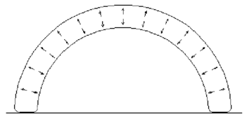
Because of the disadvantages above listed, a new and more revolutionized system was designed called “air inflated system”. This system is formed by tubes of different textile materials filled with low pressure air. Textile materials are designed to support any external action, from fire resistance to climate aggression.
|
| Figure 3: Functional schema of the “Air inflated system” |
Some innovations are needed to ensure the construction of this inflatable system such as new and powerful pattern design tools or simulation codes with the possibility to predict the behavior of the solution under different load cases.
|
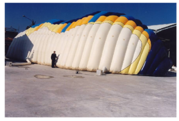
| Figure 4: Inflatable pavilion (250m) formed by an assembly of low pressure tubes built for the mobile exhibition for the Gaudi Year of Construction Artisans, Barcelona 2002 |
Structures formed by inflatable tubes
The structure is formed by an assembly of low pressure tubes formed by different textile materials. The diameter of the tubes depends on the needs of the project and the dimensions of the space to be covered. The inflating pressure varies between 50 and 150 kg/m accordingly to the structural stiffness required. This pressure can be obtained by simple fans with low noise production. Therefore, the use of air-compressors and expensive or noisy inflating equipment is not required.
The standard material chosen in the inflatable structures built by the authors is Polyamide 6.6 of high strength and 0.3 mm thickness. UV and fire resistance coatings which provide a M1 material type are used. Typical strengths in the transversal and longitudinal directions are 36 and 30 kg/cm, respectively. The limit strains are 24.5% along the transversal direction and 25% in the longitudinal direction. The weight of the material is 208 g/m. Obviously, higher strength materials and alternative coatings can be used to meet other structural and thermal requirements.
The double membrane layer helps towards the thermal protection of the inner space. A disadvantage, however, is the excessive amount of textile material, as the surface of the lateral walls of the tubes amounts for the 30% of the total surface of the membrane structure. This disadvantage can be overcome using the tension-rope system described next.
Low pressure membrane structures within tension ropes
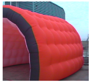
These double membrane inflatable structures are formed by two membrane layers connected by tension ropes. The ropes are placed at strategic points in order to preserve the desired shape of the structure. The amount of membrane material in these structures is considerable less than in the tubular structures with the corresponding savings in the weight and the overall cost of the structure. An example of a structure of this type recently built by the company BuildAir (www.buildair.com) is shown in Fig. 5.
|
| Figure 5: Cylindrical pavilion formed by a double layer membrane with tension ropes |
3 Structural Analysis and Pattern Design
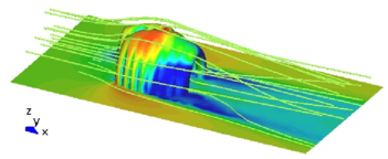
Traditional methods for analysis of inflatable structure are based on membrane and tube theories [9, 10]. A more detailed analysis of inflatable structures can be performed using membrane finite elements allowing for large displacement analysis combined with one-dimensional elements to model the tension ropes, if necessary. The membrane formulation used is an extension of the rotation-free shell finite element formulation developed by the authors in recent years [11-15]. The following analysis conditions are typically considered.
- Coupled aerodynamic analysis in order to compute the evolution of the shape of the structure under different wind conditions. Aerodynamic load are also essential to design the anchoring system. The fluid-dynamic analysis is based in the stabilized finite element method developed by the authors [16]. The coupled fluid-structure interaction formulation used is an extension of that derived by the authors for ship hydrodynamic analysis [17].
- Thermal analysis in order to study the evolution of temperature in the textile material under prescribed external temperature changes. The thermal analysis can be complemented by the computation of the temperature evolution in the interior of the structure using the finite element method.
|
| Figure 6: Aerodynamic analysis results performed by CIMNE. Air particles around ECCOMAS 2000 inflated pavilion developed by BuildAir |
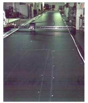
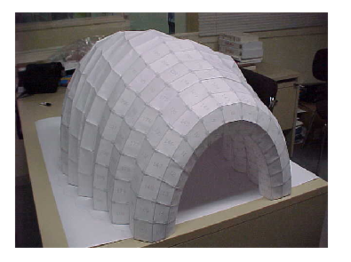
The accurate pattern design is essential to ensure the correct shape of the structure after the inflating process. The pattern design procedure developed by the authors is based on the isoparametric finite element concept. Patterns are assimilated to finite element patches and are defined using the prepost processing system GiD developed at CIMNE [18]. A mapping into the isoparametric space allows representing the pattern geometry in a 2D system, thus providing the necessary information for the cutting machine using a standard plotting system (Fig. 7). Fig. 8 shows a scale model in paper used to verify the pattern design of the ECCOMAS 2000 inflatable pavilion formed by low pressure tubes.
|
| Figure 7: Plotter system used to cut the membrane patches |
|
| Figure 8: Paper model of an inflatable pavilion formed by low pressure tubes |
4 Architectural Design
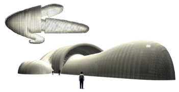
The use of structures formed by low pressure inflatable tubes is ideal to cover large temporal spaces. Innovative design allows offering clients unique products.
The exclusive and never seen design generates a great distinct impact for the users of inflatable system. The systems is ideal for applications that require temporal covers and pavilions with an exclusive design as a differentiation aspect. Effectiveness and easy assembly are the main aspects to be considered. The design possibilities that the system allow are really enormous, offering to the client covers with a great personalised and refined design value.
|
| Figure 9: Example of extremely complex design of an inflatable mobile theatre |
5 Development Lines
New requirements have been identified and different solutions were developed in order to increase the possibilities of low pressure inflatable structures to success into the civil engineering and architecture market.
Some of the aspects developed by the authors in order to increase the use of inflatable structures and to construct a new generation of inflatable covers for civil and architectural applications are:
- Regarding the manufacturing aspect, the development and optimisation of the procedures aiming to change from a non-industrial construction process to knowledge based industrial process using latest Information Technologies (IT) tools. An important objective was the reduction of production costs in order to make inflatable structures more competitive versus other temporary cover systems
- This requires multidisciplinary studies of the production chain, such as new lighter and cheaper materials and the optimisation of the production process.
- Much effort was dedicated to the pattern generation and optimisation in order to reduce material lost and makes the material work in a better way. New software to generate and optimise patterns was developed considering new material properties (anisotropy, multi layers, real shape of the fabrics, etc.)
- Alternative energy supplies and new ways to inflate the covers were developed to ensure the use of inflatable solutions in marginal or disaster areas. It was important to optimise the use of gas (air or helium) inside the structure in order to minimise fluid lost.
- Material and mechanical behaviour of inflated structures follow different design principles from those typically used in standard concrete, steel or aluminium structures. Hence new conceptual and manufacturing concepts were developed in order to satisfy the increasing market demands while preserving necessary safety, comfort and operational requirements. Structural control for wind pressure and temperature loads was mandatory in these cases.
The security of inflatable buildings was kept in mind in the implementation of every development.
6 Applications
6.1 ECCOMAS 2000 Pavilion
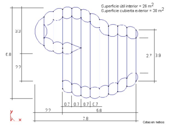
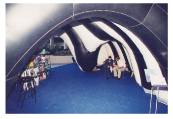
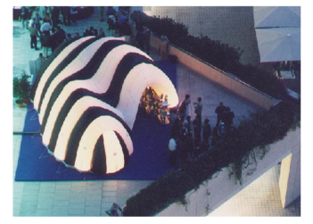
An inflatable structure formed by 11 low pressure tubes was designed and built as the Pavilion of the International Center for Numerical Methods in Engineering (CIMNE) at the ECCOMAS Congress held in Barcelona on 11-15 September 2000 [19]. The construction required 500 m of Polyamide 6.6 material and some 1000 meters of sewing. Figs. [10-11] show a plant of the inflatable pavilion and a view of the exterior and interior during the exhibition.
|
| Figure 10: Plan of the ECCOMAS 2000 Pavilion using 11 low pressure tubes. Distances in meters |
| |
| |
| Figure 11: Exterior and interior views of the ECCOMAS 2000 inflatable pavilion | |
6.2 Gaudi Institute Exhibition Pavilion
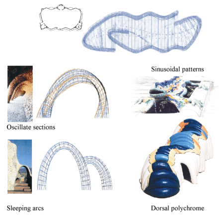
An inflatable pavilion has been recently built by the company BuildAir in cooperation with the authors for the Gaudi Institute of Barcelona for a mobile exhibition on Construction Artisans.
Architectural design and concepts
|
| Figure 12: Architectural concepts as basis of the Gaudi pavilion design |
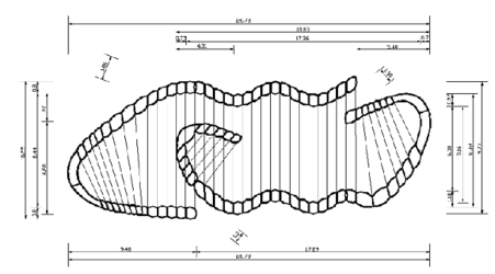
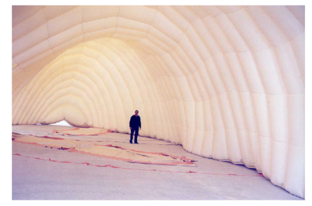
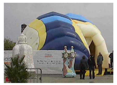
The construction technique was based on the low pressure tube technology described. A total of 58 tubes were used to cover a surface of 250m. A plan of the structure and different views of the inflated pavilion reaching height of 8.50 mts are shown in Figs. [13-15].
|
| Figure 13: Plan view of the inflatable pavilion for the Gaudi Institute Exhibition using 58 low pressure tubes |
|
| Figure 14: Interior view of the inflated Gaudi Institute Exhibition pavilion |
|
| Figure 15: Front view of the inflated Gaudi Institute Exhibition pavilion |
Public Engineering Constructions exhibition
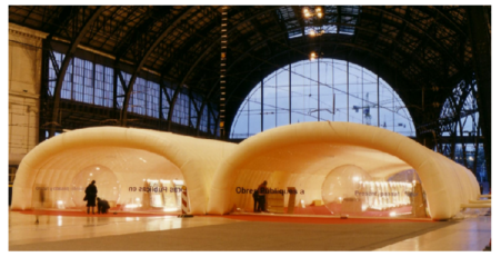
This is another example of applications of inflatable pavilions to generate temporal spaces for itinerant exhibitions. In this case, Buildair in cooperation with the authors had designed and constructed a space of 1.200 m formed by an array of 6 pavilions of 11 meters by 16 meters.
|
| Figure 16: External view of inflatable pavilions, Francia Train Station. Barcelona, diciembre 2003 |
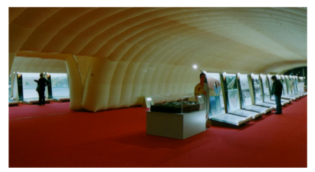
This pavilion hold the exhibition ``Las obras públicas en Catalunya organized by Colegio de Ingenieros de Caminos Canales y Puertos, RENFE and CEDEX (Ministerio de Fomento) during November and December 2003.
|
| Figure 17: Interior view of the pavilion |
|
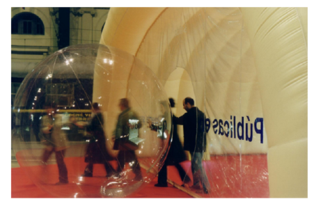
| Figure 18: Door detail, formed by an inflatable ball |
BIBLIOGRAPHY
1 Inflatable structures for engineering and architecture applications. BuildAir, www.buildair.com, 2002
2 Plant RH, Liapis S, Telionis DP (1996) Flood Protection using Inflatable Dams. Natural Disaster Reduction Conference. Washington December 3-5:264-265
3 Rehmet M, Bauder C, Schäfer, I Kröplin BH (1994) Solar Powered Airship Project. International Conference Remotely Piloted Vehicles, Bristol
4 Beukers A, Molder OV, Vermeeren CAJR (2001) Inflatable Structures in Space Engineering. Journal of the IASS
5 ILC Dover, World leader in innovative flexible solutions (2000). http://www.ilcdover.com
6 New Methodologies for Design and Manufacturing of Inflated Structures (INFLAST) (Brite-Euram Contract Nº BRPR-CT97-0448). Consortium: CIMNE: BAZAN, S.A., CASA, S.A., NOVURANIA, S.p.A., IRD a/s, Universitat Stutt-gart, Airship Technologies, GmbH. Project finished on May 2000
7 Sadeh WZ, Criswell ME A generic inflatable structure for a lunar/martian base. Proceeding of the Ebgineering, Construction and Operations in Space IV 1146-1156
8 Nowak PS, Sadeh WZ, Morroni LA (1992), "Geometric modeling of inflatable structures for lunar base. Journal of Aerospace Engineering 5(3):311-322
9 Herzog T (1976) Pneumatische Kontruktionen: Bauten aus Membranan und Luft. Hatje-Verlag Stuttgart
10 Kawabata M, Ishii K (1994) Study of structural characteristics of Air inflated Beam Structures. Proceedings of the IASS-ASCE International Symposium, Atlanta 742–751
11 Rojek J, Pérez D, Cipriano J, Miquel J, Oñate E (1999) A finite elements methodol-ogy for analysis of inflatable structures. IASS Conference, Madrid
12 Oñate E, Zarate F (2000) Rotational free plate and shell elements. International Journal of Numerical Methods in Engineering 47:557-603
13 Marcipar J, Sarrablo V, Pérez D, Cipriano J, Miquel J, Oñate E (2000) Design and analysis of double membrane inflated covers presented. Presented in the MARAS 2000 Conference, Wessex
14 Taylor RL (2001) Finite element analysis of membrane structures (2001) Research Publication, CIMNE PI 103
15 Oñate E, Cendoya P, Miquel J, Rojek J (2002) Non Linear explicit dynamics analysis of shells structures using the BST rotation-free triangle. Submitted to Engineer-ing Computations
16 Oñate E (2000) A stabilized finite element meted for incompressible viscous flows us-ing a finite increment calculus formulation. Comput. Meth. Appl. Mech. Engng. 182(1-2):355-370
17 E. Oñate, J. García, "A finite element method for fluid-structure interaction with surface waves using a finite calculus formulation", Comput. Meth. Appl., Mech. Engng., 191, 635-660, 2001
18 GiD (2002) The personal pre/postprocesador. CIMNE, Barcelona, www.gid.cimne.upc.es.
19 European Congress on Computational Method in Appl. Science and Engineering (ECCOMAS) (2000), Barcelona 11-15 September, www.cimne.upc.es/ECCOMAS
20 Marcipar J, Oñate E, Sarrablo V (2002) Inflatable Structures. An integration of inno-vative materials, design, analysis and construction methods. Invited paper. Fifth World Congress on Computational Mechanics, Vienna
Document information
Published on 01/01/2005
DOI: 10.1007/1-4020-3317-6_15
Licence: CC BY-NC-SA license
Share this document
Keywords
claim authorship
Are you one of the authors of this document?