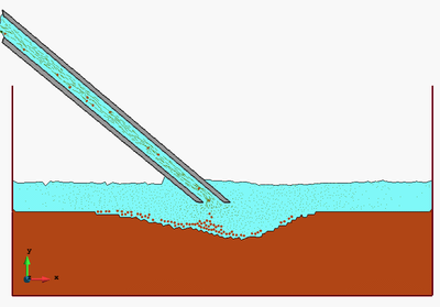
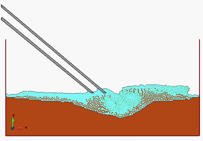
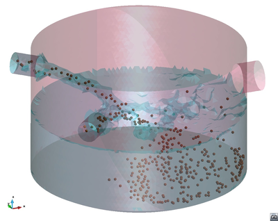
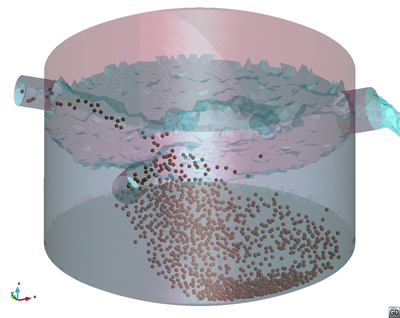
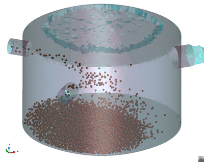
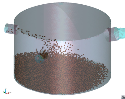
| (29 intermediate revisions by 3 users not shown) | |||
| Line 1: | Line 1: | ||
| − | |||
| − | |||
==Abstract== | ==Abstract== | ||
We present a Lagrangian numerical technique for the analysis of flows incorporating physical particles of different sizes. The numerical approach is based on the Particle Finite Element Method (PFEM) which blends concepts from particle-based techniques and the FEM. The basis of the Lagrangian formulation for particulate flows and the procedure for modelling the motion of small and large particles that are submerged in the fluid are described in detail. The numerical technique for analysis of this type of multiscale particulate flows using a stabilized mixed velocity-pressure formulation and the PFEM is also presented. Examples of application of the PFEM to several particulate flows problems are given. | We present a Lagrangian numerical technique for the analysis of flows incorporating physical particles of different sizes. The numerical approach is based on the Particle Finite Element Method (PFEM) which blends concepts from particle-based techniques and the FEM. The basis of the Lagrangian formulation for particulate flows and the procedure for modelling the motion of small and large particles that are submerged in the fluid are described in detail. The numerical technique for analysis of this type of multiscale particulate flows using a stabilized mixed velocity-pressure formulation and the PFEM is also presented. Examples of application of the PFEM to several particulate flows problems are given. | ||
| − | ''' | + | '''Keywords''': Lagrangian analysis, Multiscale particulate flows, Particle finite element method |
==1 Introduction== | ==1 Introduction== | ||
| Line 35: | Line 33: | ||
<div id='img-2'></div> | <div id='img-2'></div> | ||
{| style="text-align: center; border: 1px solid #BBB; margin: 1em auto; width: 100%;max-width: 100%;" | {| style="text-align: center; border: 1px solid #BBB; margin: 1em auto; width: 100%;max-width: 100%;" | ||
| + | |- | ||
| + | | style="text-align: center;"| (a) | ||
| + | | style="text-align: center;"| (b) | ||
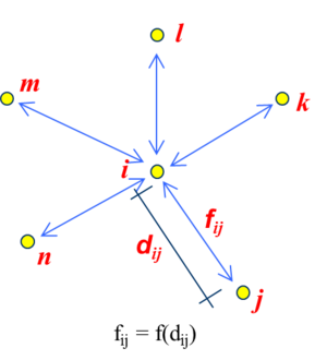
|- | |- | ||
|[[Image:draft_Samper_928603926-Imagen3.png|400px|]] | |[[Image:draft_Samper_928603926-Imagen3.png|400px|]] | ||
| − | |[[Image:draft_Samper_928603926-Imagen4.png|400px| | + | |[[Image:draft_Samper_928603926-Imagen4.png|400px|]] |
|- style="text-align: center; font-size: 75%;" | |- style="text-align: center; font-size: 75%;" | ||
| colspan="2" | '''Figure 2:''' (a) Particles of different sizes surrounding the nodes in a FEM mesh. (b) Representative volume for a node (in shadowed darker colour) | | colspan="2" | '''Figure 2:''' (a) Particles of different sizes surrounding the nodes in a FEM mesh. (b) Representative volume for a node (in shadowed darker colour) | ||
| Line 314: | Line 315: | ||
{| style="text-align: center; border: 1px solid #BBB; margin: 1em auto; width: 100%;max-width: 100%;" | {| style="text-align: center; border: 1px solid #BBB; margin: 1em auto; width: 100%;max-width: 100%;" | ||
|- | |- | ||
| − | | | + | | colspan="2" style="text-align: center;font-size:75%;"| (a) Contact between microscopic particles |
| − | + | ||
|- | |- | ||
| + | |colspan="2" |[[Image:draft_Samper_928603926-contact-particles.png|300px|]] | ||
| + | |- | ||
| + | | colspan="2" style="text-align: center;font-size:75%;"| Forces between two microscopic particles act in the direction of the line connecting their radii | ||
| + | |- | ||
| + | | colspan="2" style="text-align: center;padding-top:10px;font-size:75%;"| (b) Contact “a la DEM” between macroscopic particles [34] | ||
| + | |- | ||
| + | |[[Image:draft_Samper_928603926-contact.png|400px|]] | ||
|[[Image:draft_Samper_928603926-Fig3.png|400px|]] | |[[Image:draft_Samper_928603926-Fig3.png|400px|]] | ||
| − | |[[Image:draft_Samper_928603926-Fig5.png| | + | |- |
| + | |colspan="2" style="text-align: center;"|[[Image:draft_Samper_928603926-Fig5.png|300px]] | ||
| + | |- | ||
| + | | colspan="2" style="text-align: center;padding-top:10px;"| <math>\begin{array}{ll}{\bf F}_n^{ij}=K_n {\bf u}_n^{ij}+C_n \dot {\bf u}_n^{ij} & \quad {\bf u}_n^{ij},{\bf u}_s^{ij} \hbox{relative displacements in the normal and}\\ | ||
| + | {\bf F}_s^{ij} =K_s {\bf u}_s^{ij}& \quad \hbox{tangential directions to a contact interface}\end{array}</math> | ||
|- style="text-align: center; font-size: 75%;" | |- style="text-align: center; font-size: 75%;" | ||
| colspan="2" | '''Figure 4:''' Interacting forces between microscopic (a) and macroscopic (b) particles | | colspan="2" | '''Figure 4:''' Interacting forces between microscopic (a) and macroscopic (b) particles | ||
| Line 548: | Line 559: | ||
<div class="center" style="font-size: 75%;"> | <div class="center" style="font-size: 75%;"> | ||
| − | [[File:Draft_Samper_928603926_2153_Box1.png| | + | [[File:Draft_Samper_928603926_2153_Box1.png|500px]] |
'''Box 1'''. Element form of the matrices and vectors in Eqs.(27) for 2D problems</div> | '''Box 1'''. Element form of the matrices and vectors in Eqs.(27) for 2D problems</div> | ||
| Line 561: | Line 572: | ||
Eqs.([[#8 FEM discretization|8]]) are solved in time with an implicit Newton-Raphson type iterative scheme <span id='citeF-3'></span><span id='citeF-9'></span><span id='citeF-58'></span><span id='citeF-60'></span>[[#cite-3|[3,9,58,60]]]. The basic steps within a time interval <math display="inline">[n,n+1]</math> are:<br/> | Eqs.([[#8 FEM discretization|8]]) are solved in time with an implicit Newton-Raphson type iterative scheme <span id='citeF-3'></span><span id='citeF-9'></span><span id='citeF-58'></span><span id='citeF-60'></span>[[#cite-3|[3,9,58,60]]]. The basic steps within a time interval <math display="inline">[n,n+1]</math> are:<br/> | ||
| − | * Initialize variables: <math display="inline">({}^{n+1} | + | * Initialize variables: <math display="inline">({}^{n+1}{\bf x}^1,{}^{n+1}\bar {\bf v}^1,{}^{n+1}\bar{\bf p}^1,{}^{n+1}n_f^i, {}^{n+1}\bar{\bf r}^1_m)\equiv \left\{{}^{n}{\bf x},{}^{n}\bar{\bf v},{}^{n}\bar{\bf p},{}^{n} n_f ,{}^{n}\bar{\bf r}_m \right\}</math>. |
* Iteration loop: <math display="inline">k=1,\cdots , NITER</math>.<p> For each iteration. | * Iteration loop: <math display="inline">k=1,\cdots , NITER</math>.<p> For each iteration. | ||
| − | |||
| − | + | '''''Step 1. Compute the nodal velocity increments''''' <math>\Delta \bar {\bf v}</math> | |
| − | + | ||
| − | + | ||
| − | From Eq.([[#8 FEM discretization| | + | From Eq.([[#8 FEM discretization|27]]a), we deduce |
<span id="eq-31"></span> | <span id="eq-31"></span> | ||
| Line 578: | Line 586: | ||
{| style="text-align: left; margin:auto;" | {| style="text-align: left; margin:auto;" | ||
|- | |- | ||
| − | | style="text-align: center;" | <math>{}^{n+1}{H}_v^i \Delta \bar {v} = - {}^{n+1}\bar{\ | + | | style="text-align: center;" | <math>{}^{n+1}{\bf H}_v^i \Delta \bar {\bf v} = - {}^{n+1}\bar{\bf r}_m^k \rightarrow \Delta \bar{\bf v} </math> |
|} | |} | ||
| − | | style="width: 5px;text-align: right;" | ( | + | | style="width: 5px;text-align: right;" | (28a) |
|} | |} | ||
| − | with the momentum residual <math display="inline">\bar{r}_m</math> and the iteration matrix <math display="inline">{H}_v</math> given by | + | with the momentum residual <math display="inline">\bar{\bf r}_m</math> and the iteration matrix <math display="inline">{\bf H}_v</math> given by |
<span id="eq-32"></span> | <span id="eq-32"></span> | ||
| Line 591: | Line 599: | ||
{| style="text-align: left; margin:auto;" | {| style="text-align: left; margin:auto;" | ||
|- | |- | ||
| − | | style="text-align: center;" | <math>\bar{\ | + | | style="text-align: center;" | <math>\bar{\bf r}_m = {\bf M}_0 {\dot{\bar{\bf v}}} + {\bf K}\bar{\bf v}+{\bf Q}\bar {\bf p}-{\bf f}_v\quad , \quad {\bf H}_v = \frac{1}{\Delta t} {\bf M}_0 + {\bf K} + {\bf K}_v </math> |
|} | |} | ||
| − | | style="width: 5px;text-align: right;" | ( | + | | style="width: 5px;text-align: right;" | (28b) |
|} | |} | ||
| Line 604: | Line 612: | ||
{| style="text-align: left; margin:auto;" | {| style="text-align: left; margin:auto;" | ||
|- | |- | ||
| − | | style="text-align: center;" | <math> | + | | style="text-align: center;" | <math>{\bf K}_v^e = \int _{{}^nV^e} {\bf B}^T {\bf m} \theta \Delta t\kappa {\bf m}^T {\bf B}dV </math> |
|} | |} | ||
| − | | style="width: 5px;text-align: right;" | ( | + | | style="width: 5px;text-align: right;" | (28c) |
|} | |} | ||
| − | + | '''''Step 2. Update the velocities''''' | |
<span id="eq-34"></span> | <span id="eq-34"></span> | ||
| Line 617: | Line 625: | ||
{| style="text-align: left; margin:auto;" | {| style="text-align: left; margin:auto;" | ||
|- | |- | ||
| − | | style="text-align: center;" | <math>\hbox{Fluid nodes:}~~{}^{n+1}\bar{v}^{k+1}= {}^{n+1}\bar{v}^k + \Delta \bar{v} </math> | + | | style="text-align: center;" | <math>\hbox{Fluid nodes:}~~{}^{n+1}\bar{\bf v}^{k+1}= {}^{n+1}\bar{\bf v}^k + \Delta \bar{\bf v} </math> |
|} | |} | ||
| − | | style="width: 5px;text-align: right;" | ( | + | | style="width: 5px;text-align: right;" | (29a) |
|} | |} | ||
| Line 628: | Line 636: | ||
{| style="text-align: left; margin:auto;" | {| style="text-align: left; margin:auto;" | ||
|- | |- | ||
| − | | style="text-align: center;" | <math>\hbox{Rigid particles:}~~\left\{\begin{array}{l}{}^{n+1/2}\dot{u}_{j} = {}^{n-1/2}\dot{u}_{j} + {}^{n}\ddot{u}_{j}^{k+1} \Delta t\\ \dot{u}_{j} = \frac{1}{m_j} {}^{n}{F}_{j}^{k+1} ~~,~~j=1,N_p \end{array}\right. </math> | + | | style="text-align: center;" | <math>\hbox{Rigid particles:}~~\left\{\begin{array}{l}{}^{n+1/2}\dot{\bf u}_{j} = {}^{n-1/2}\dot{\bf u}_{j} + {}^{n}\ddot{\bf u}_{j}^{k+1} \Delta t\\ \dot{\bf u}_{j} = \frac{1}{m_j} {}^{n}{\bf F}_{j}^{k+1} ~~,~~j=1,N_p \end{array}\right. </math> |
|} | |} | ||
| − | | style="width: 5px;text-align: right;" | ( | + | | style="width: 5px;text-align: right;" | (29b) |
|} | |} | ||
| − | + | '''''Step 3. Compute the nodal pressures''''' <math> {}^{n+1}\bar{\bf p}^{k+1}</math> | |
| − | From Eq.([[#eq-30| | + | From Eq.([[#eq-30|27b]]) we obtain |
<span id="eq-36"></span> | <span id="eq-36"></span> | ||
| Line 643: | Line 651: | ||
{| style="text-align: left; margin:auto;" | {| style="text-align: left; margin:auto;" | ||
|- | |- | ||
| − | | style="text-align: center;" | <math>{}^{n+1} | + | | style="text-align: center;" | <math>{}^{n+1} {\bf H}_p^i {}^{n+1}\bar{\bf p}^{k+1}= \frac{1}{\Delta t} {\bf M}_1 {}^{n+1}\bar{\bf p}^i + {\bf Q}^T {}^{n+1}\bar{\bf v}^{k+1}+ {}^{n+1}\bar{\bf f}^{i}_p \rightarrow {}^{n+1}\bar{\bf p}^{k+1} </math> |
|} | |} | ||
| − | | style="width: 5px;text-align: right;" | ( | + | | style="width: 5px;text-align: right;" | (30a) |
|} | |} | ||
| Line 656: | Line 664: | ||
{| style="text-align: left; margin:auto;" | {| style="text-align: left; margin:auto;" | ||
|- | |- | ||
| − | | style="text-align: center;" | <math> | + | | style="text-align: center;" | <math>{\bf H}_p = \frac{1}{\Delta t} {\bf M}_1 + {\bf L} + {\bf M}_b </math> |
|} | |} | ||
| − | | style="width: 5px;text-align: right;" | ( | + | | style="width: 5px;text-align: right;" | (30b) |
|} | |} | ||
| − | + | '''''Step 4. Update the coordinates of the fluid nodes and particles''''' | |
<span id="eq-38"></span> | <span id="eq-38"></span> | ||
| Line 669: | Line 677: | ||
{| style="text-align: left; margin:auto;" | {| style="text-align: left; margin:auto;" | ||
|- | |- | ||
| − | | style="text-align: center;" | <math>\hbox{Fluid nodes:}~~{}^{n+1}{x}^{k+1}_i= {}^{n+1}{x}^k_i + \frac{1}{2} ({}^{n+1}\bar{v}^{k+1}_i + {}^{n}\bar{v}_i)\Delta t \quad ,~~ i=1,N </math> | + | | style="text-align: center;" | <math>\hbox{Fluid nodes:}~~{}^{n+1}{\bf x}^{k+1}_i= {}^{n+1}{\bf x}^k_i + \frac{1}{2} ({}^{n+1}\bar{\bf v}^{k+1}_i + {}^{n}\bar{\bf v}_i)\Delta t \quad ,~~ i=1,N </math> |
|} | |} | ||
| − | | style="width: 5px;text-align: right;" | ( | + | | style="width: 5px;text-align: right;" | (31a) |
|} | |} | ||
| Line 680: | Line 688: | ||
{| style="text-align: left; margin:auto;" | {| style="text-align: left; margin:auto;" | ||
|- | |- | ||
| − | | style="text-align: center;" | <math>\hbox{Rigid particles:}~~\left\{\begin{array}{l}{}^{n+1}{u}_{i}^{k+1} = {}^{n}{u}_{i}^{k+1} + {}^{n+1/2}\dot{u}_{i}^{k+1}\Delta t\\[.4cm] {}^{n+1}{x}^{k+1}_i = {}^{n}{x}_i + {}^{n+1}{u}^{k+1}_i \quad ,~~ i=1,N_p \end{array}\right. </math> | + | | style="text-align: center;" | <math>\hbox{Rigid particles:}~~\left\{\begin{array}{l}{}^{n+1}{\bf u}_{i}^{k+1} = {}^{n}{\bf u}_{i}^{k+1} + {}^{n+1/2}\dot{\bf u}_{i}^{k+1}\Delta t\\[.4cm] {}^{n+1}{\bf x}^{k+1}_i = {}^{n}{\bf x}_i + {}^{n+1}{\bf u}^{k+1}_i \quad ,~~ i=1,N_p \end{array}\right. </math> |
|} | |} | ||
| − | | style="width: 5px;text-align: right;" | ( | + | | style="width: 5px;text-align: right;" | (31b) |
|} | |} | ||
| − | + | '''''Step 5. Compute the fluid volume fractions for each node''''' <math>{}^{n+1}{n}^{k+1}_{f_i}</math> '''''via Eq.(2)''''' | |
| − | + | '''''Step 6. Compute forces and torques on particles:''''' <math>{}^{n+1}{\bf F}^{k+1}_i,{}^{n+1}{\bf T}^{k+1}_i~ ,~i=1,N_p</math> | |
| − | + | '''''Step 7. Compute particle-to-fluid nodes:''''' <math>({}^{n+1}{\bf f}^{pf}_i)^{k+1} = - ({}^{n+1}{\bf f}^{fp}_i)^{k+1} ~ ,~ i=1,N</math> '''''with''''' <math>{\bf f}^{fp}_i</math> '''''computed by Eq.(18)''''' | |
| − | + | '''''Step 8. Check convergence''''' | |
Verify the following conditions: | Verify the following conditions: | ||
| Line 701: | Line 709: | ||
{| style="text-align: left; margin:auto;" | {| style="text-align: left; margin:auto;" | ||
|- | |- | ||
| − | | style="text-align: center;" | <math>\begin{array}{c}\displaystyle \Vert {}^{n+1}\bar {v}^{k+1}- {}^{n+1}\bar{v}^{k}\Vert \le e_v \Vert {}^{n}\bar {v}\Vert \\ \displaystyle \Vert {}^{n+1}\bar {p}^{k+1}-{}^{n+1}\bar {p}^k\Vert \le e_p \Vert {}^{n}\bar{p}\Vert \end{array} </math> | + | | style="text-align: center;" | <math>\begin{array}{c}\displaystyle \Vert {}^{n+1}\bar {\bf v}^{k+1}- {}^{n+1}\bar{\bf v}^{k}\Vert \le e_v \Vert {}^{n}\bar {\bf v}\Vert \\ \displaystyle \Vert {}^{n+1}\bar {\bf p}^{k+1}-{}^{n+1}\bar {\bf p}^k\Vert \le e_p \Vert {}^{n}\bar{\bf p}\Vert \end{array} </math> |
|} | |} | ||
| − | | style="width: 5px;text-align: right;" | ( | + | | style="width: 5px;text-align: right;" | (32) |
|} | |} | ||
where <math display="inline">e_v</math> and <math display="inline">e_p</math> are prescribed error norms for the nodal velocities and the nodal pressures, respectively. In the examples solved in this work we have set <math display="inline">e_v = e_p=10^{-3}</math>. | where <math display="inline">e_v</math> and <math display="inline">e_p</math> are prescribed error norms for the nodal velocities and the nodal pressures, respectively. In the examples solved in this work we have set <math display="inline">e_v = e_p=10^{-3}</math>. | ||
| − | If both conditions ([[#eq-40| | + | If both conditions ([[#eq-40|32]]) are satisfied then make <math display="inline">n \leftarrow n+1 </math> and proceed to the next time step. |
Otherwise, make the iteration counter <math display="inline">k \leftarrow k+1 </math> and repeat Steps 1–8. | Otherwise, make the iteration counter <math display="inline">k \leftarrow k+1 </math> and repeat Steps 1–8. | ||
| − | '''Remark 5.''' In Eqs.([[#''Step 1. Compute the nodal velocity increments <math>\Delta \bar {v}</math>''| | + | '''Remark 5.''' In Eqs.([[#''Step 1. Compute the nodal velocity increments <math>\Delta \bar {v}</math>''|28]])–([[#eq-40|32]]) <math display="inline">{}^{n+1}(\cdot )</math> denotes the values of a matrix or a vector computed using the nodal unknowns at time <math display="inline">n+1</math>. In our work the derivatives and integrals in the iteration matrices <math display="inline">{\bf H}_v</math> and <math display="inline">{\bf H}_p</math> and the residual vector <math display="inline">\bar{\bf r}_m</math> are computed on the ''discretized geometry at time'' <math display="inline">n</math> (i.e. <math display="inline">V^e = {}^{n}V^e</math>) while the nodal force vectors <math display="inline">{\bf f}_v</math> and <math display="inline">{\bf f}_p</math> are computed on the current configuration at time <math display="inline">n+1</math>. This is equivalent to using an ''updated Lagrangian formulation'' <span id='citeF-3'></span><span id='citeF-12'></span><span id='citeF-44'></span><span id='citeF-59'></span>[[#cite-3|[3,12,44,59]]]. |
| − | '''Remark 6.''' The tangent “bulk” stiffness matrix <math display="inline"> | + | '''Remark 6.''' The tangent “bulk” stiffness matrix <math display="inline">{\bf K}_v</math> in the iteration matrix <math display="inline">{\bf H}_v</math> of Eq.([[#eq-32|28b]]) accounts for the changes of the pressure due to the velocity. Including matrix <math display="inline">{\bf K}_v</math> in <math display="inline">{\bf H}_v</math> has proven to be essential for the fast convergence, mass preservation and overall accuracy of the iterative solution <span id='citeF-11'></span><span id='citeF-45'></span>[[#cite-11|[11,45]]]. |
| − | '''Remark 7.''' The parameter <math display="inline">\theta </math> in <math display="inline">{K}_v</math> (<math display="inline">0< \theta \le 1</math>) has the role of preventing the ill-conditioning of the iteration matrix <math display="inline">{H}_v</math> for very large values of the speed of sound in the fluid that lead to a dominant role of the terms of the tangent bulk stiffness matrix <math display="inline">{K}_v</math>. An adequate selection of <math display="inline">\theta </math> also improves the overall accuracy of the numerical solution and the preservation of mass for large time steps. Details of the derivation of Eq.(28c) can be found in <span id='citeF-45'></span>[[#cite-45|[45]]]. | + | '''Remark 7.''' The parameter <math display="inline">\theta </math> in <math display="inline">{\bf K}_v</math> (<math display="inline">0< \theta \le 1</math>) has the role of preventing the ill-conditioning of the iteration matrix <math display="inline">{\bf H}_v</math> for very large values of the speed of sound in the fluid that lead to a dominant role of the terms of the tangent bulk stiffness matrix <math display="inline">{\bf K}_v</math>. An adequate selection of <math display="inline">\theta </math> also improves the overall accuracy of the numerical solution and the preservation of mass for large time steps. Details of the derivation of Eq.(28c) can be found in <span id='citeF-45'></span>[[#cite-45|[45]]]. |
| − | '''Remark 8.''' The iteration matrix <math display="inline"> | + | '''Remark 8.''' The iteration matrix <math display="inline">{\bf H}_v</math> in Eq.([[#eq-31|28a]]) is an ''approximation of the exact tangent matrix'' in the updated Lagrangian formulation for a quasi/fully incompressible fluid <span id='citeF-44'></span>[[#cite-44|[44]]]. The simplified form of <math display="inline">{\bf H}_v</math> used in this work has yielded very good results with convergence achieved for the nodal velocities and pressure in 3–4 iterations in all the problems analyzed. |
| − | '''Remark 9.''' The time step within a time interval <math display="inline">[n,n+1]</math> has been chosen as <math display="inline">\Delta t =\min \left(\frac{^n l_{\min }^e}{\vert {}^n{v}\vert _{\max }},\Delta t_b\right)</math> where <math display="inline">^n l_{\min }^e</math> is the minimum characteristic distance of all elements in the mesh, with <math display="inline">l^e</math> computed as explained in Section 6, <math display="inline">\vert ^n{v}\vert _{\max }</math> is the maximum value of the modulus of the velocity of all nodes in the mesh and <math display="inline">\Delta t_b</math> is the critical time step of all nodes approaching a solid boundary <span id='citeF-45'></span>[[#cite-45|[45]]]. | + | '''Remark 9.''' The time step within a time interval <math display="inline">[n,n+1]</math> has been chosen as <math display="inline">\Delta t =\min \left(\frac{^n l_{\min }^e}{\vert {}^n{\bf v}\vert _{\max }},\Delta t_b\right)</math> where <math display="inline">^n l_{\min }^e</math> is the minimum characteristic distance of all elements in the mesh, with <math display="inline">l^e</math> computed as explained in Section 6, <math display="inline">\vert ^n{\bf v}\vert _{\max }</math> is the maximum value of the modulus of the velocity of all nodes in the mesh and <math display="inline">\Delta t_b</math> is the critical time step of all nodes approaching a solid boundary <span id='citeF-45'></span>[[#cite-45|[45]]]. |
==10 About the particle finite element method (PFEM)== | ==10 About the particle finite element method (PFEM)== | ||
| Line 773: | Line 781: | ||
{| style="text-align: center; border: 1px solid #BBB; margin: 1em auto; width: 100%;max-width: 100%;" | {| style="text-align: center; border: 1px solid #BBB; margin: 1em auto; width: 100%;max-width: 100%;" | ||
|- | |- | ||
| − | |[[Image:draft_Samper_928603926-Imagen2.png| | + | | (a) |
| − | |[[ | + | | (b) |
| − | |- style="text-align: center | + | |- |
| − | | colspan="2" | '''Figure 6:''' (a) Large particles (in dark shadow) surrounded by a finite element mesh. The contact interface is shown in lighter shadow. (b) Contact interface between two objects treated as large particles and between an object and a wall | + | |[[Image:draft_Samper_928603926-Imagen2.png|350px|]] |
| + | |[[File:Draft_Samper_928603926_1361_contact-PFEM-particles.png|450px]] | ||
| + | |- style="text-align: center;" | ||
| + | | colspan="2" style="text-align: center; font-size: 75%;padding-top:10px;" | '''Figure 6:''' (a) Large particles (in dark shadow) surrounded by a finite element mesh. The contact interface is shown in lighter shadow. (b) Contact interface between two objects treated as large particles and between an object and a wall | ||
|} | |} | ||
| Line 818: | Line 829: | ||
{| style="text-align: center; border: 1px solid #BBB; margin: 1em auto; width: 90%;max-width: 100%;" | {| style="text-align: center; border: 1px solid #BBB; margin: 1em auto; width: 90%;max-width: 100%;" | ||
|- | |- | ||
| − | |[[Image:draft_Samper_928603926-bed-erosion-2.png| | + | |[[Image:draft_Samper_928603926-bed-erosion-2.png|440px|Modeling of bed erosion with the PFEM. The mass of the eroded domain is assigned to the fluid node k]] |
|- style="text-align: center; font-size: 75%;" | |- style="text-align: center; font-size: 75%;" | ||
| colspan="1" | '''Figure 8:''' Modeling of bed erosion with the PFEM. The mass of the eroded domain is assigned to the fluid node <math>k</math> | | colspan="1" | '''Figure 8:''' Modeling of bed erosion with the PFEM. The mass of the eroded domain is assigned to the fluid node <math>k</math> | ||
| Line 848: | Line 859: | ||
{| style="text-align: center; border: 1px solid #BBB; margin: 1em auto; width: 100%;max-width: 100%;" | {| style="text-align: center; border: 1px solid #BBB; margin: 1em auto; width: 100%;max-width: 100%;" | ||
|- | |- | ||
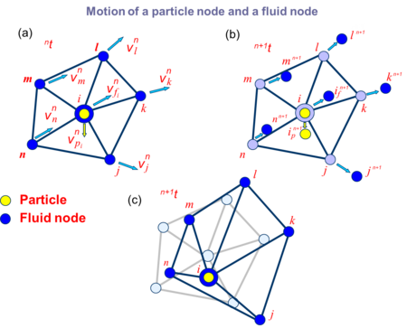
| − | |[[Image:draft_Samper_928603926-motion-particle-node.png| | + | |[[Image:draft_Samper_928603926-motion-particle-node.png|450px|Nodal algorithm for tracking the motion of particles submerged in a fluid. (a) Particle i is coincident with a fluid node. (b) Update the position of the particle and the adjacent nodes. (c) Regeneration of the fluid mesh consistent with the new particle position]] |
|- style="text-align: center; font-size: 75%;" | |- style="text-align: center; font-size: 75%;" | ||
| colspan="1" | '''Figure 9:''' Nodal algorithm for tracking the motion of particles submerged in a fluid. (a) Particle <math>i</math> is coincident with a fluid node. (b) Update the position of the particle and the adjacent nodes. (c) Regeneration of the fluid mesh consistent with the new particle position | | colspan="1" | '''Figure 9:''' Nodal algorithm for tracking the motion of particles submerged in a fluid. (a) Particle <math>i</math> is coincident with a fluid node. (b) Update the position of the particle and the adjacent nodes. (c) Regeneration of the fluid mesh consistent with the new particle position | ||
| Line 856: | Line 867: | ||
{| style="text-align: center; border: 1px solid #BBB; margin: 1em auto; width: 100%;max-width: 100%;" | {| style="text-align: center; border: 1px solid #BBB; margin: 1em auto; width: 100%;max-width: 100%;" | ||
|- | |- | ||
| − | | | + | |(a) |
| − | | | + | |(b) |
|- | |- | ||
| − | | | + | |style="vertical-align: top;|[[Image:draft_Samper_928603926-one-particle1.png|320px|]] |
| + | |style="vertical-align: top;|[[Image:draft_Samper_928603926-one-particle-contours.png|400px|]] | ||
| + | |- | ||
| + | |colspan="2" | (c) | ||
| + | |- | ||
| + | | colspan="2"|[[Image:draft_Samper_928603926-Grafica-velocity.png|360px]] | ||
|- style="text-align: center; font-size: 75%;" | |- style="text-align: center; font-size: 75%;" | ||
| colspan="2" | '''Figure 10:''' Cylindrical particles falling in a water container. 2D PFEM solution using the nodal algorithm for tracking the particle motion. (a) Mesh and particle at a certain instant. (b) Contours of the vertical velocity module. (c) Evolution of the vertical velocity of the particle until a steady state solution is found <span id='citeF-6'></span><span id='citeF-15'></span>[[#cite-6|[6,15]]] | | colspan="2" | '''Figure 10:''' Cylindrical particles falling in a water container. 2D PFEM solution using the nodal algorithm for tracking the particle motion. (a) Mesh and particle at a certain instant. (b) Contours of the vertical velocity module. (c) Evolution of the vertical velocity of the particle until a steady state solution is found <span id='citeF-6'></span><span id='citeF-15'></span>[[#cite-6|[6,15]]] | ||
| Line 876: | Line 892: | ||
{| style="text-align: center; border: 1px solid #BBB; margin: 1em auto; width: 100%;max-width: 100%;" | {| style="text-align: center; border: 1px solid #BBB; margin: 1em auto; width: 100%;max-width: 100%;" | ||
|- | |- | ||
| − | |[[Image:draft_Samper_928603926-three-particles2.png| | + | |[[Image:draft_Samper_928603926-three-particles2.png|400px|Motion of three macroscopic particles in a water sloshing problem within a tank. PFEM results obtained using the nodal algorithm for particle tracking]] |
|- style="text-align: center; font-size: 75%;" | |- style="text-align: center; font-size: 75%;" | ||
| colspan="1" | '''Figure 12:''' Motion of three macroscopic particles in a water sloshing problem within a tank. PFEM results obtained using the nodal algorithm for particle tracking | | colspan="1" | '''Figure 12:''' Motion of three macroscopic particles in a water sloshing problem within a tank. PFEM results obtained using the nodal algorithm for particle tracking | ||
| Line 885: | Line 901: | ||
|- | |- | ||
|[[Image:draft_Samper_928603926-tanque-particles-entrada_clara.png|400px|]] | |[[Image:draft_Samper_928603926-tanque-particles-entrada_clara.png|400px|]] | ||
| − | |[[ | + | | |
| + | [[File:Draft_Samper_928603926_4412_tanque-particles-clara_clara.png|400px|PFEM analysis of the penetration of a collection of spherical (macroscopic) particles into a water container]] | ||
|- style="text-align: center; font-size: 75%;" | |- style="text-align: center; font-size: 75%;" | ||
| colspan="2" | '''Figure 13:''' PFEM analysis of the penetration of a collection of spherical (macroscopic) particles into a water container | | colspan="2" | '''Figure 13:''' PFEM analysis of the penetration of a collection of spherical (macroscopic) particles into a water container | ||
|} | |} | ||
| + | |||
| + | ==12 Examples== | ||
| + | |||
| + | We present the study of a several problems involving the transport of macroscopic and large particles in fluid flows. The problems are schematic representations of particulate flows occurring in practical problems of civil and environmental engineering and industrial problems. | ||
| + | |||
| + | Most problems studied have been solved with the PFEM using the nodal algorithm for the transport of macroscopic particles described in the previous section. An exception are the problems in Section 12.6 dealing with the vertical transport of spherical particles in a cylinder where the standard immersed approach for the transport macroparticles described in Sections 1–4 was used and the fluid equations were solved with an Eulerian flow solver implemented in the Kratos open-source software platform of CIMNE <span id='citeF-24'></span>[[#cite-24|[24]]]. | ||
| + | |||
| + | ===12.1 Erosion of a slope adjacent to the shore due to sea waves=== | ||
| + | |||
| + | Figure [[#img-14|14]] shows a representative example of the progressive erosion of a soil mass adjacent to the shore due to sea waves and the subsequent falling into the sea of a 2D object representing the section of a lorry. The object has been modeled as a rigid solid. Note that the eroded soil particles accumulate at the sea bottom. | ||
| + | |||
| + | This example, although still quite simple and schematic, evidences the possibility of the PFEM for modeling FSSI problems involving soil erosion, free surface waves and rigid/deformable structures. | ||
| + | |||
<div id='img-14'></div> | <div id='img-14'></div> | ||
| Line 901: | Line 931: | ||
| colspan="2" | '''Figure 14:''' Falling of a lorry into the sea by erosion of the underlying soil mass due to the action of waves | | colspan="2" | '''Figure 14:''' Falling of a lorry into the sea by erosion of the underlying soil mass due to the action of waves | ||
|} | |} | ||
| + | |||
| + | ===12.2 Landslide falling on houses=== | ||
| + | |||
| + | Figure [[#img-15|15]] shows two instants of the 2D simulation with PFEM of the motion of a collection of macroscopic particles as they slide over an inclined wall and fall into a water container. | ||
| + | |||
| + | The PFEM is particularly suited for the modelling and simulation of landslides and their effect in the surrounding structures. Figure [[#img-16|16]] shows an schematic 2D simulation of a landslide falling on two adjacent constructions. The landslide material has been assumed to behave as a pure viscoplastic material modelled as a non-Newtonian viscous incompressible fluid <span id='citeF-57'></span>[[#cite-57|[57]]]. Other applications of the PFEM to the modelling of landslides can be found in <span id='citeF-8'></span><span id='citeF-49'></span>[[#cite-8|[8,49]]]. | ||
| + | |||
<div id='img-15'></div> | <div id='img-15'></div> | ||
| Line 919: | Line 956: | ||
| colspan="2" | '''Figure 16:''' 3D PFEM simulation of a landslide falling on four houses | | colspan="2" | '''Figure 16:''' 3D PFEM simulation of a landslide falling on four houses | ||
|} | |} | ||
| + | |||
| + | ===12.3 Dragging of rocks by a water stream=== | ||
| + | |||
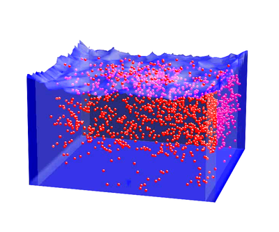
| + | Figure [[#img-17|17]] shows the dragging of a collection of rocks modelled as large rigid particles of arbitrary shape by the action of a water stream. The particles move due to the action of the water forces on the particles computed by integrating the pressure and the viscous stresses in the elements surrounding each particle. | ||
<div id='img-17'></div> | <div id='img-17'></div> | ||
| Line 931: | Line 972: | ||
| colspan="2" | '''Figure 17:''' 3D PFEM results for the dragging of a collection of large rocks by a water stream | | colspan="2" | '''Figure 17:''' 3D PFEM results for the dragging of a collection of large rocks by a water stream | ||
|} | |} | ||
| − | |||
| − | |||
| − | |||
| − | |||
| − | |||
| − | |||
| − | |||
| − | |||
| − | |||
| − | |||
| − | |||
| − | |||
| − | |||
| − | |||
| − | |||
| − | |||
| − | |||
| − | |||
| − | |||
| − | |||
| − | |||
| − | |||
===12.4 Suction of cohesive material submerged in water=== | ===12.4 Suction of cohesive material submerged in water=== | ||
| Line 963: | Line 982: | ||
{| style="text-align: center; border: 1px solid #BBB; margin: 1em auto; width: 100%;max-width: 100%;" | {| style="text-align: center; border: 1px solid #BBB; margin: 1em auto; width: 100%;max-width: 100%;" | ||
|- | |- | ||
| − | |[[ | + | | |
| + | [[File:Draft_Samper_928603926_8538_suction1.png|400px|]] | ||
|[[Image:draft_Samper_928603926-suction2.png|400px|]] | |[[Image:draft_Samper_928603926-suction2.png|400px|]] | ||
|- | |- | ||
| − | |[[ | + | | |
| + | [[File:Draft_Samper_928603926_8004_suction3.png|400px|]] | ||
|[[Image:draft_Samper_928603926-suction4.png|400px|2D PFEM analysis of the detachment and suction of cohesive material submerged in water. The last picture shows the erosion of the bed material after the impact of the mixture of water and eroded particles falling from within the tube]] | |[[Image:draft_Samper_928603926-suction4.png|400px|2D PFEM analysis of the detachment and suction of cohesive material submerged in water. The last picture shows the erosion of the bed material after the impact of the mixture of water and eroded particles falling from within the tube]] | ||
|- style="text-align: center; font-size: 75%;" | |- style="text-align: center; font-size: 75%;" | ||
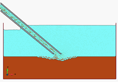
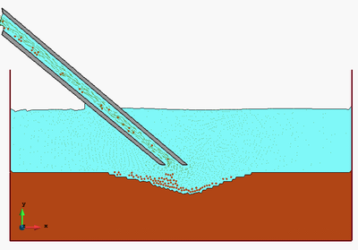
| Line 1,009: | Line 1,030: | ||
{| style="text-align: center; border: 1px solid #BBB; margin: 1em auto; width: 100%;max-width: 100%;" | {| style="text-align: center; border: 1px solid #BBB; margin: 1em auto; width: 100%;max-width: 100%;" | ||
|- | |- | ||
| − | |[[Image:draft_Samper_928603926-ascending-particles1b.png| | + | |style="vertical-align: top;|[[Image:draft_Samper_928603926-ascending-particles1b.png|350px|]] |
| − | |[[Image:draft_Samper_928603926-ascending-particles2.png| | + | |style="vertical-align: top;|[[Image:draft_Samper_928603926-ascending-particles2.png|350px|Transport of spherical macroparticles up to the free surface of a tube filled with water. Particles move up with a prescribed velocity until they accumulate on the free surface. Results obtained with a coupled DEM-Eulerian CFD code <span id='citeF-24'></span>[[#cite-24|[24]]]]] |
|- style="text-align: center; font-size: 75%;" | |- style="text-align: center; font-size: 75%;" | ||
| colspan="2" | '''Figure 21:''' Transport of spherical macroparticles up to the free surface of a tube filled with water. Particles move up with a prescribed velocity until they accumulate on the free surface. Results obtained with a coupled DEM-Eulerian CFD code <span id='citeF-24'></span>[[#cite-24|[24]]] | | colspan="2" | '''Figure 21:''' Transport of spherical macroparticles up to the free surface of a tube filled with water. Particles move up with a prescribed velocity until they accumulate on the free surface. Results obtained with a coupled DEM-Eulerian CFD code <span id='citeF-24'></span>[[#cite-24|[24]]] | ||
| Line 1,018: | Line 1,039: | ||
{| style="text-align: center; border: 1px solid #BBB; margin: 1em auto; width: 100%;max-width: 100%;" | {| style="text-align: center; border: 1px solid #BBB; margin: 1em auto; width: 100%;max-width: 100%;" | ||
|- | |- | ||
| − | |[[Image:draft_Samper_928603926-interaction-six-jets1.png| | + | |(a) |
| − | |[[Image:draft_Samper_928603926-interaction-six-jets2.png| | + | |(b) |
| + | |- | ||
| + | |[[Image:draft_Samper_928603926-interaction-six-jets1.png|350px|]] | ||
| + | |[[Image:draft_Samper_928603926-interaction-six-jets2.png|350px|]] | ||
| + | |- | ||
| + | |(c) | ||
| + | |(d) | ||
|- | |- | ||
| − | |[[Image:draft_Samper_928603926-interaction-six-jets3.png| | + | |[[Image:draft_Samper_928603926-interaction-six-jets3.png|350px|]] |
| − | |[[Image:draft_Samper_928603926-interaction-six-jets4.png| | + | |[[Image:draft_Samper_928603926-interaction-six-jets4.png|350px|]] |
|- style="text-align: center; font-size: 75%;" | |- style="text-align: center; font-size: 75%;" | ||
| colspan="2" | '''Figure 22:''' Interaction of eight jets of ascending air bubbles with a thick layer of 200.000 spherical particles that fall down within a cylinder filled with water. Numerical results obtained with a coupled DEM-Eulerian CFD code <span id='citeF-24'></span>[[#cite-24|[24]]] | | colspan="2" | '''Figure 22:''' Interaction of eight jets of ascending air bubbles with a thick layer of 200.000 spherical particles that fall down within a cylinder filled with water. Numerical results obtained with a coupled DEM-Eulerian CFD code <span id='citeF-24'></span>[[#cite-24|[24]]] | ||
| Line 1,057: | Line 1,084: | ||
This research was supported by the Advanced Grant project SAFECON of the European Research Council. | This research was supported by the Advanced Grant project SAFECON of the European Research Council. | ||
| − | == | + | ==References== |
<div id="cite-1"></div> | <div id="cite-1"></div> | ||
| − | + | [[#citeF-1|[1]]] Anderson T, Jackson R. Fluid mechanical description of fluidized beds: equation of motion. Industrial & Engineering Chemical Fundamentals, 6(4):527–539 | |
<div id="cite-2"></div> | <div id="cite-2"></div> | ||
| − | + | [[#citeF-2|[2]]] Avci B, Wriggers P, (2012) A DEM-FEM coupling approach for the direct numerical simulation of 3D particulate flows. Journal of Applied Mechanics, 79(1), 7 pages | |
<div id="cite-3"></div> | <div id="cite-3"></div> | ||
| − | + | [[#citeF-3|[3]]] T. Belytschko, W.K. Liu, B. Moran, Non linear finite element for continua and structures, 2d Edition, Wiley, 2013. | |
<div id="cite-4"></div> | <div id="cite-4"></div> | ||
| − | + | [[#citeF-4|[4]]] Carbonell JM, Oñate E, Suárez B (2010) Modeling of ground excavation with the Particle Finite Element Method. Journal of Engineering Mechanics (ASCE) 136(4):455–463 | |
<div id="cite-5"></div> | <div id="cite-5"></div> | ||
| − | + | [[#citeF-5|[5]]] Carbonell JM, Oñate E, Suárez B (2013) Modelling of tunnelling processes and cutting tool wear with the Particle Finite Element Method (PFEM). Accepted in Comput. Mech. (2013) DOI:10.1007/s00466-013-0835-x | |
<div id="cite-6"></div> | <div id="cite-6"></div> | ||
| − | + | [[#citeF-6|[6]]] Clift R, Grace JR, Weber ME (1978) Bubbles, drops and particles. Academic Press, New York | |
<div id="cite-7"></div> | <div id="cite-7"></div> | ||
| − | + | [7] Coussy O (2004) Poromechanics. Wiley | |
<div id="cite-8"></div> | <div id="cite-8"></div> | ||
| − | + | [[#citeF-8|[8]]] Cremonesi M, Frangi A, Perego U (2011) A Lagrangian finite element approach for the simulation of water-waves induced by landslides. Computers & Structures 89:1086–1093 | |
<div id="cite-9"></div> | <div id="cite-9"></div> | ||
| − | + | [[#citeF-9|[9]]] Donea J, Huerta A (2003) Finite element method for flow problems. J. Wiley | |
<div id="cite-10"></div> | <div id="cite-10"></div> | ||
| − | + | [[#citeF-10|[10]]] Edelsbrunner H, Mucke EP (1999) Three dimensional alpha shapes. ACM Trans. Graphics 13:43–72 | |
<div id="cite-11"></div> | <div id="cite-11"></div> | ||
| − | + | [[#citeF-11|[11]]] Franci A, Oñate E, Carbonell JM (2013) On the effect of the tangent bulk stiffness matrix in the analysis of free surface Lagrangian flows using PFEM. Research Report CIMNE PI402 | |
<div id="cite-12"></div> | <div id="cite-12"></div> | ||
| − | + | [[#citeF-12|[12]]] Franci A, Oñate E, Carbonell JM (2014b) Unified updated Lagrangian formulation for fluid-structure interaction problems. Research Report CIMNE PI404 | |
<div id="cite-13"></div> | <div id="cite-13"></div> | ||
| − | + | [[#citeF-13|[13]]] Gidaspow D (1994) Multiphase flow and fluidization. Continuum and Kinetic Theory Description, Academic Press, 467 pages | |
<div id="cite-14"></div> | <div id="cite-14"></div> | ||
| − | + | [[#citeF-14|[14]]] Healy DP, Young DB (2005) Full Lagrangian method for calculating particle concentration field in dilute gas-particle flows. Proc. Roy. Soc., London A: Mathematical, Physical and Engineering Sciences, 461(2059):2197–2225 | |
<div id="cite-15"></div> | <div id="cite-15"></div> | ||
| − | + | [[#citeF-15|[15]]] Heider A, Levespiel O (1989) Drag coefficient and terminal velocity of spherical and nonspherical particles. Powder Technol. 58:63–70 | |
<div id="cite-16"></div> | <div id="cite-16"></div> | ||
| − | + | [[#citeF-16|[16]]] Hilton J, Cleary P (2013) Dust modelling using a combined CFD and discrete element formulation. Int. J. Num. Meth. Fluids, 72(5):528-549 | |
<div id="cite-17"></div> | <div id="cite-17"></div> | ||
| − | + | [[#citeF-17|[17]]] Idelsohn SR, Oñate E, Del Pin F (2004) The particle finite element method: a powerful tool to solve incompressible flows with free-surfaces and breaking waves. Int. Journal for Numerical Methods in Engineering, 61(7):964–989 | |
<div id="cite-18"></div> | <div id="cite-18"></div> | ||
| − | + | [[#citeF-18|[18]]] Idelsohn SR, Marti J, Limache A, Oñate E (2008) Unified Lagrangian formulation for elastic solids and incompressible fluids: Application to fluid-structure interaction problems via the PFEM. Comput Methods Appl Mech Engrg. 197:1762–1776 | |
<div id="cite-19"></div> | <div id="cite-19"></div> | ||
| − | + | [19] Idelsohn SR, Mier-Torrecilla M, Oñate E (2009) Multi-fluid flows with the Particle Finite Element Method. Comput Methods Appl Mech Engrg. 198:2750–2767 | |
<div id="cite-20"></div> | <div id="cite-20"></div> | ||
| − | + | [[#citeF-20|[20]]] Idelsohn SR, Oñate E (2010) The challenge of mass conservation in the solution of free-surface flows with the fractional-step method: Problems and solutions. Int. J. Numer. Meth. Biomed. Engng. 26:1313–-1330 | |
<div id="cite-21"></div> | <div id="cite-21"></div> | ||
| − | + | [[#citeF-21|[21]]] Jajcevic D, Siegmann E, Radeke C, Khinast JG (2013) Large-scale CFD-DEM simulations of fluidized granular systems. Chemical Engineering Science, 98:298–310 | |
<div id="cite-22"></div> | <div id="cite-22"></div> | ||
| − | + | [[#citeF-22|[22]]] Jackson R (2000), The dynamics of fluidized particles. Cambridge Monographs on Mechanics, Cambridge Univ. Press | |
<div id="cite-23"></div> | <div id="cite-23"></div> | ||
| − | + | [[#citeF-23|[23]]] Kafui DK, Thornton C, Adams MJ (2002) Discrete particle-continuum fluid modelling of gas-solid fluidised beds. Chemical Engng. Science, 57(13):2395–2410 | |
<div id="cite-24"></div> | <div id="cite-24"></div> | ||
| − | + | [[#citeF-24|[24]]] Kratos (2014) Open source software platform for multiphysics computations. CIMNE, Barcelona, www.cimne.com/kratos | |
<div id="cite-25"></div> | <div id="cite-25"></div> | ||
| − | + | [25] Larese A, Rossi R, Oñate E, Idelsohn SR (2008) Validation of the Particle Finite Element Method (PFEM) for simulation of free surface flows. Engineering Computations 25(4):385–425 | |
<div id="cite-26"></div> | <div id="cite-26"></div> | ||
| − | + | [[#citeF-26|[26]]] Liu SH, Sun DA (2002). Simulating the collapse of unsaturated soil by DEM. Int. J. Num. Anal. Meth. in Geomechanics, 26:633–646 | |
<div id="cite-27"></div> | <div id="cite-27"></div> | ||
| − | + | [[#citeF-27|[27]]] Oliver X, Cante JC, Weyler R, González C, Hernández J (2007) Particle finite element methods in solid mechanics problems. In: Oñate E, Owen R (Eds) Computational Plasticity. Springer, Berlin, pp 87–103 | |
<div id="cite-28"></div> | <div id="cite-28"></div> | ||
| − | + | [[#citeF-28|[28]]] Oliver X, Hartmann S, Cante JC, Wyler R, Hernández J (2009) A contact domain method for large deformation frictional contact problems. Part 1: theoretical basis. Comput Methods Appl Mech Eng 198:2591–2606 | |
<div id="cite-29"></div> | <div id="cite-29"></div> | ||
| − | + | [[#citeF-29|[29]]] Oñate E (1998) Derivation of stabilized equations for advective-diffusive transport and fluid flow problems. Comput. Meth. Appl. Mech. Engng. 151:233–267 | |
<div id="cite-30"></div> | <div id="cite-30"></div> | ||
| − | + | [[#citeF-30|[30]]] Oñate E (2000) A stabilized finite element method for incompressible viscous flows using a finite increment calculus formulation. Comput Methods Appl Mech Engrg. 182(1–2):355–370 | |
<div id="cite-31"></div> | <div id="cite-31"></div> | ||
| − | + | [[#citeF-31|[31]]] Oñate E, García J (2001) A finite element method for fluid-structure interaction with surface waves using a finite calculus formulation. Comput. Meth. Appl. Mech. Engrg. 191:635–660 | |
<div id="cite-32"></div> | <div id="cite-32"></div> | ||
| − | + | [[#citeF-32|[32]]] Oñate E (2003) Multiscale computational analysis in mechanics using finite calculus: an introduction. Comput. Meth. Appl. Mech. Engrg. 192(28-30):3043–3059 | |
<div id="cite-33"></div> | <div id="cite-33"></div> | ||
| − | + | [[#citeF-33|[33]]] Oñate E (2004) Possibilities of finite calculus in computational mechanics. Int. J. Num. Meth. Engng. 60(1):255–281 | |
<div id="cite-34"></div> | <div id="cite-34"></div> | ||
| − | + | [[#citeF-34|[34]]] Oñate E, Rojek J, (2004b) Combination of discrete element and finite element methods for dynamic analysis of geomechanics problems. Comput. Meth. Appl. Mech. Engrg. 193:3087–3128 | |
<div id="cite-35"></div> | <div id="cite-35"></div> | ||
| − | + | [[#citeF-35|[35]]] Oñate E, Idelsohn SR, Del Pin F, Aubry R (2004c) The particle finite element method. An overview. Int. J. Comput. Methods 1(2):267–307 | |
<div id="cite-36"></div> | <div id="cite-36"></div> | ||
| − | + | [[#citeF-36|[36]]] Oñate E, Celigueta MA, Idelsohn SR (2006a) Modeling bed erosion in free surface flows by the Particle Finite Element Method, Acta Geotechnia 1(4):237–252 | |
<div id="cite-37"></div> | <div id="cite-37"></div> | ||
| − | + | [[#citeF-37|[37]]] Oñate E, Valls A, García J (2006b) FIC/FEM formulation with matrix stabilizing terms for incompressible flows at low and high Reynold's numbers. Computational Mechanics 38 (4-5):440–455 | |
<div id="cite-38"></div> | <div id="cite-38"></div> | ||
| − | + | [[#citeF-38|[38]]] Oñate E, García J, Idelsohn SR, Del Pin F (2006c) FIC formulations for finite element analysis of incompressible flows. Eulerian, ALE and Lagrangian approaches. Comput. Meth. Appl. Mech. Engng. 195(23-24):3001–3037 | |
<div id="cite-39"></div> | <div id="cite-39"></div> | ||
| − | + | [[#citeF-39|[39]]] Oñate E, Valls A, García J (2007) Computation of turbulent flows using a finite calculus-finite element formulation. Int. J. Numer. Meth. Engng. 54:609–637 | |
<div id="cite-40"></div> | <div id="cite-40"></div> | ||
| − | + | [[#citeF-40|[40]]] Oñate E, Idelsohn SR, Celigueta MA, Rossi R (2008) Advances in the particle finite element method for the analysis of fluid-multibody interaction and bed erosion in free surface flows. Comput. Meth. Appl. Mech. Engng. 197(19-20):1777–1800 | |
<div id="cite-41"></div> | <div id="cite-41"></div> | ||
| − | + | [[#citeF-41|[41]]] Oñate E (2009), Structural analysis with the finite element method. Linear statics. Volume 1. Basis and Solids. CIMNE-Springer | |
<div id="cite-42"></div> | <div id="cite-42"></div> | ||
| − | + | [42] Oñate E, Rossi R, Idelsohn SR, Butler K (2010) Melting and spread of polymers in fire with the particle finite element method. Int. J. Numerical Methods in Engineering, 81(8):1046–1072 | |
<div id="cite-43"></div> | <div id="cite-43"></div> | ||
| − | + | [[#citeF-43|[43]]] Oñate E, Celigueta MA, Idelsohn SR, Salazar F, Suárez B (2011) Possibilities of the particle finite element method for fluid-soil-structure interaction problems. Computational Mechanics, 48(3):307–318. | |
<div id="cite-44"></div> | <div id="cite-44"></div> | ||
| − | + | [[#citeF-44|[44]]] Oñate E, Carbonell JM (2013) Updated Lagrangian finite element formulation for quasi and fully incompressible fluids. Research Report PI393, CIMNE. Submitted to Comput. Mechanics | |
<div id="cite-45"></div> | <div id="cite-45"></div> | ||
| − | + | [[#citeF-45|[45]]] Oñate E, Franci A, Carbonell JM (2014) Lagrangian formulation for finite element analysis of quasi-incompressible fluids with reduced mass losses. Accepted for publication in Int. J. Num. Meth. in Fluids, 74(10):699–-731 | |
<div id="cite-46"></div> | <div id="cite-46"></div> | ||
| − | + | [[#citeF-46|[46]]] Oñate E, Franci A, Carbonell JM (2014b) A Particle Finite Element Method (PFEM) for analysis of industrial forming processes. Accepted for publication in Comput. Mechanics | |
<div id="cite-47"></div> | <div id="cite-47"></div> | ||
| − | + | [[#citeF-47|[47]]] Patankar NA, Joseph DD (2001) Lagrangian numerical simulation of particulate flows. Int. J. Multiphase Flow, 27:1685–1706 | |
<div id="cite-48"></div> | <div id="cite-48"></div> | ||
| − | + | [48] Ryzhakov P, Oñate E, Rossi R, Idelsohn SR (2012) Improving mass conservation in simulation of incompressible flows. Int. J. Numer. Meth. Engng. 90(12):1435–1451 | |
<div id="cite-49"></div> | <div id="cite-49"></div> | ||
| − | + | [[#citeF-49|[49]]] Salazar F, Oñate E, Morán R (2012) Modelación numérica del deslizamiento de ladeu en embalses mediante el método de partículos y elementos finitos (PFEM). Rev. Int. Meth. Num. Cal. Dis. Ing., 28(2):112–123 | |
<div id="cite-50"></div> | <div id="cite-50"></div> | ||
| − | + | [[#citeF-50|[50]]] Shamy UE, Zeghal M (2005) Coupled continuum–discrete model for saturated granular soils. J. Engineering Mechanics (ASCE), 131(4):413–-426 | |
<div id="cite-51"></div> | <div id="cite-51"></div> | ||
| − | + | [[#citeF-51|[51]]] Sommerfeld M, van Wachen B, Oliemans R (Eds) (2008) Best practice guideliens for computational fluid dynamics of dispersed multiphase flows. European Research Community on Flow, Turbulence and Combustion (ERCOFTAC), Imperial College London. | |
<div id="cite-52"></div> | <div id="cite-52"></div> | ||
| − | + | [52] Tang B, Li JF, Wang TS (2009) Some improvements on free surface simulation by the particle finite element method. Int. J. Num. Methods in Fluids, 60(9):1032–-1054 | |
<div id="cite-53"></div> | <div id="cite-53"></div> | ||
| − | + | [[#citeF-53|[53]]] van Wachen B, Oliveira ES (2010) An immersed boundary method for interacting particles. ERCOFTAC Bulletin 82, 17–22 March 2010 | |
<div id="cite-54"></div> | <div id="cite-54"></div> | ||
| − | + | [[#citeF-54|[54]]] Wang X, Zhang LT, Liu WK (2009) On computational issues of the immersed finite element method. J. Comp. Physics, 228:2535–2551 | |
<div id="cite-55"></div> | <div id="cite-55"></div> | ||
| − | + | [[#citeF-55|[55]]] Li X, Chu X, Sheng DC (2007) A saturated discrete particle model and characteristic-based SPH method in granular materials. Int. J. Numer. Meth. Engng., 72:858–882 | |
<div id="cite-56"></div> | <div id="cite-56"></div> | ||
| − | + | [[#citeF-56|[56]]] Zhang LT, Gerstenberg A, Wang X, Liu WK (2004) Immersed finite element method. Comput. Meth. Appl. Mech. Engrg., 193(21-22):2051–2067 | |
<div id="cite-57"></div> | <div id="cite-57"></div> | ||
| − | + | [[#citeF-57|[57]]] Zienkiewicz OC, Jain PC, Oñate E (1978) Flow of solids during forming and extrusion: some aspects of numerical solutions. ''Int. J. Solids Struct.'', 14:15–38 | |
<div id="cite-58"></div> | <div id="cite-58"></div> | ||
| − | + | [[#citeF-58|[58]]] Zienkiewicz OC, Taylor RL, Zhu JZ (2005) The finite element method. The basis. 6th Ed., Elsevier | |
<div id="cite-59"></div> | <div id="cite-59"></div> | ||
| − | + | [[#citeF-59|[59]]] Zienkiewicz OC, Taylor RL (2005) The finite element method for solid and structural mechanics. 6th Ed., Elsevier | |
<div id="cite-60"></div> | <div id="cite-60"></div> | ||
| − | + | [[#citeF-60|[60]]] Zienkiewicz OC, Taylor RL, Nithiarasu P (2005) The finite element method for fluid dynamics. 6th Ed., Elsevier | |
<div id="cite-61"></div> | <div id="cite-61"></div> | ||
| − | + | [[#citeF-61|[61]]] Zohdi T (2007) An introduction to modelling and simulation of particulate flows. SIAM, Computational Science and Engineering | |
<div id="cite-62"></div> | <div id="cite-62"></div> | ||
| − | + | [[#citeF-62|[62]]] Zohdi T, Wriggers P (2007) Computation of strongly coupled multifield interaction in particle-fluid systems. Comput. Meth. Appl. Mech. Engng., 196:3927–3950 | |
Latest revision as of 14:07, 3 June 2019
Abstract
We present a Lagrangian numerical technique for the analysis of flows incorporating physical particles of different sizes. The numerical approach is based on the Particle Finite Element Method (PFEM) which blends concepts from particle-based techniques and the FEM. The basis of the Lagrangian formulation for particulate flows and the procedure for modelling the motion of small and large particles that are submerged in the fluid are described in detail. The numerical technique for analysis of this type of multiscale particulate flows using a stabilized mixed velocity-pressure formulation and the PFEM is also presented. Examples of application of the PFEM to several particulate flows problems are given.
Keywords: Lagrangian analysis, Multiscale particulate flows, Particle finite element method
1 Introduction
The study of fluid flows containing particles of different sizes (hereafter called particulate flows) is relevant to many areas of engineering and applied sciences. In this work we are concerned with particulate flows containing small to large particles. This type of flows is typical in slurry flows originated by natural hazards such as floods, tsunamis and landslides, as well as in many processes of the bio-medical and pharmaceutical industries, in the manufacturing industry and in the oil and gas industry (i.e. cuttings transport in boreholes), among other applications [1,2,6,13,14,16,21,22,23,26,47,50,51,55,61,62].
Our interest in this work is the modelling and simulation of free surface particulate quasi-incompressible flows containing particles of different sizes using a particular class of Lagrangian FEM termed the Particle Finite Element Method (PFEM, www.cimne.com/pfem) [4,5,8,11,17-20,25,27,28,35,36,38,40,42-46]. The PFEM treats the mesh nodes in the fluid and solid domains as particles which can freely move and even separate from the main fluid domain. A mesh connects the nodes discretizing the domain where the governing equations are solved using a stabilized FEM.
In Lagrangian analysis procedures (such as the PFEM) the motion of fluid particles is tracked during the transient solution. Hence, the convective terms vanish in the momentum equations and no numerical stabilization is needed. Another source of instability, however, remains in the numerical solution of Lagrangian flows, that due to the treatment of the incompressibility constraint which requires using a stabilized numerical method.
In this work we use a stabilized Lagrangian formulation that has excellent mass preservation features. The success of the formulation relies on the consistent derivation of a residual-based stabilized expression of the mass balance equation using the Finite Calculus (FIC) method [29-33,37-39].
The lay-out of the paper is the following. In the next section we present the basic equations for conservation of linear momentum and mass for a quasi-incompressible particulate fluid in a Lagrangian framework. The treatment of the different force terms for micro, macro and large particles are explained. Next we derive the stabilized FIC form of the mass balance equation. Then, the finite element discretization using simplicial element with equal order approximation for the velocity and the pressure is presented and the relevant matrices and vectors of the discretized problem are given. Details of the implicit transient solution of the Lagrangian FEM equations for a particulate flow using a Newton-Raphson type iterative scheme are presented. The basic steps of the PFEM for solving free-surface particulate flow problems are described.
The efficiency and accuracy of the PFEM for analysis of particulate flows are verified by solving a set of free surface and confined fluid flow problems incorporating particles of small and large sizes in two (2D) and three (3D) dimensions. The problems include the study of soil erosion, landslide situations, tsunami and flood flows, soil dredging problems and particle filling of fluid containers, among others. The excellent performance of the numerical method proposed for analysis of particulate flows is highlighted.
2 Modelling of micro, macro and large particles
Figure 1 shows a domain containing a fluid and particles of different sizes. Particles will be termed microscopic, macroscopic and large in terms of their dimensions. Microscopic and macroscopic particles will be assumed to have a cylindrical (in 2D) or spherical (in 3D) shape. These particles are modelled as rigid objects that undergo interaction forces computed in terms of the relative distance between particles (for microscropic particles) or via the physical contact between a particle and its neighbors (for macroscopic particles), as in the standard discrete element method (DEM) [2,16,34].
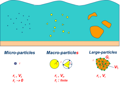
|
| Figure 1: Microscopic, macroscopic and large particles within a fluid domain |
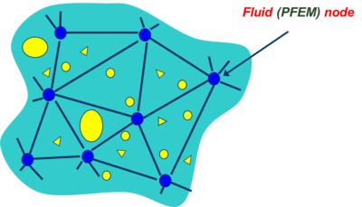
| (a) | (b) |
|
|
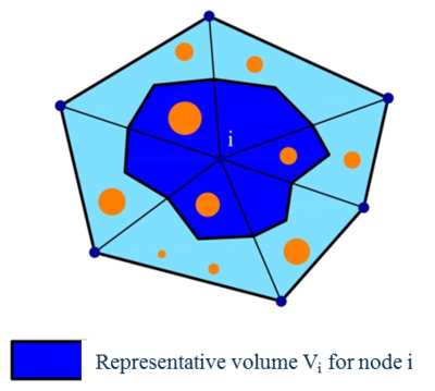
| Figure 2: (a) Particles of different sizes surrounding the nodes in a FEM mesh. (b) Representative volume for a node (in shadowed darker colour) | |
In this work microscopic and macroscopic particles are assumed to be spherical and submerged in the fluid (Figure 2). Fluid-to-particle forces are transferred to the particles via appropriate drag and buoyancy functions. Particle-to-fluid forces have equal magnitude and opposite direction as the fluid-to-particle ones and are transferred to the fluid points as an additional body force vector in the momentum equation (Figure 3). These equations, as well as the mass balance equations account for the percentage of particles in the fluid, similarly at it is done in standard immersed approaches for particulate flows [53,54,56].
 ] ]
|
| Figure 3: Immersed approach for treating the motion of physical particles in a fluid [61] |
Large particles, on the other hand, can have any arbitrary shape and they can be treated as rigid or deformable bodies. In the later case, they are discretized with the standard FEM. The forces between the fluid and the particles and viceversa are computed via fluid-structure interaction (FSI) procedures [31,60].
The following sections describe the basic governing equations for a Lagrangian particulate fluid and the computation of the forces for microscopic, macroscopic and large particles.
3 Basic governing equations for a Lagrangian particulate fluid [1,22,23,61]
Conservation of linear momentum
|
|
(1) |
In is the analysis domain, is the number of space dimensions ( for 3D problems), is the density of the fluid, and are the velocity and body force components along the th cartesian axis, respectively, are the fluid Cauchy stresses, are averaged particle-to-fluid interaction forces for which closure relations must be provided and is the fluid volume fraction defined for each node as
|
|
(2) |
where is the volume of the representative domain associated to a fluid node , is the volume of the th particle belonging to and is the number of particles contained in . Note that for a representative fluid domain containing no particles (Figure 2).
The fluid volume fraction in Eq.(1) is a continuous function that is interpolated from the nodal values in the finite element fashion [22].
Summation of terms with repeated indices is assumed in Eq.(1) and in the following, unless otherwise specified.
Remark 1. The term in Eq.(1) is the material derivative of the velocity . This term is typically computed in a Lagrangian framework as
|
|
(3a) |
with
|
|
(3b) |
where is the velocity of the material point that has the position at time , where is the coordinates vector of a point in a fixed Cartesian system. Note that the convective term, typical of Eulerian formulations, does not appear in the definition of the material derivative [3,9,60].
Constitutive equations
The Cauchy stresses in the fluid are split in the deviatoric () and pressure () components as
|
|
(4) |
where is the Kronecker delta. In this work the pressure is assumed to be positive for a tension state.
The relationship between the deviatoric stresses and the strain rates has the standard form for a Newtonian fluid [9],
|
|
(5) |
In Eq.(5) is the viscosity, and are the deviatoric and volumetric strain rates, respectively. The strain rates are related to the velocities by
|
|
(6) |
Mass conservation equation
The mass conservation equation for a particulate flow is written as
|
|
(7a) |
with
|
|
(7b) |
Expanding the material derivative and dividing Eq.(7a) by the expression of can be rewritten as
|
|
(8) |
where and is the speed of sound in the fluid.
Remark 2. For (i.e. no particles are contained in the fluid) the standard momentum and mass conservation equations for the fluid are recovered.
Boundary conditions
The boundary conditions at the Dirichlet () and Neumann () boundaries with are
|
|
(9) |
|
|
(10) |
where and are the prescribed velocities and prescribed tractions on the and boundaries, respectively and are the components of the unit normal vector to the boundary [3,9,60].
At a free surface the Neumann boundary conditions typically apply.
4 Motion of microscopic and macroscopic particles
As mentioned early, microscopic and macroscopic particles are assumed to be rigid spheres (in 3D). Their motion follows the standard law for Lagrangian particles. For the th spherical particle
|
|
(11) |
where and are the velocity and rotation vector of the center of gravity of the particle, and are the mass and rotational inertia of the particle, respectively and and are the vectors containing the forces and torques acting at the gravity center of the particle [34].
The forces acting on the th particle are computed as
|
|
(12) |
, and are the forces on the particle due to self-weight, contact interactions and fluid effects. These forces are computed as follows.
Self-weight forces
|
|
(13) |
where and are the density and the volume of the th particle, respectively and is the gravity acceleration vector.
Contact forces
|
|
(14) |
where is the number of contact interfaces for the th particle.
|
|
(15) |
where and are the normal and tangential forces acting at the th interface connecting particles and (Figure 4). These forces are computed in terms of the relative motion of the interacting particles as in the standard DEM [2,16,34].
For microscopic particles the tangential forces are neglected in Eq.(15).
Fluid-to-particle forces: , where and are, respectively, the buoyancy and drag forces on the th particle. These forces are computed as:
Buoyancy forces
|
|
(16) |
Drag forces
|
|
where is a coefficient that depends on the local Reynolds number for the particle [1,6,15,22,23] and
|
|
(17) |
In Eq.(17) and are respectively the velocity of the fluid and of the particle center, is the area of the particle surface with radius ( or for a circle or a sphere, respectively) and is a drag coefficient that depends on the particle geometry and the rugosity of its surface [22,23].
The force term in the r.h.s. of the momentum equations (Eq.(1)) is computed for each particle (in vector form) as with vector computed at each node in the fluid mesh from the drag forces as
|
|
(18) |
A continuum distribution of is obtained by interpolating its nodal values over each element in the FEM fashion.
We note that the forces on the particles due to lift effects have been neglected in the present analysis. These forces can be accounted for as explained in [22].
5 Motion of large particles
As mentioned earlier, large particles may be considered as rigid or deformable bodies. In the first case the motion follows the rules of Eq.(13) for rigid Lagrangian particles. The contact forces at the particle surface due to the adjacent interacting particles are computed using a frictional contact interface layer between particles as in the standard PFEM (Section 10.2).
The fluid forces on the particles are computing by integrating the tangential (viscous) and normal (pressure) forces at the edges of the fluid elements surrounding the particles.
Large deformable particles, on the other hand, behave as deformable bodies immersed in the fluid which are discretized via the standard FEM. Their motion can be followed using a staggered FSI scheme, or else by treating the deformable bodies and the fluid as a single continuum with different material properties. Details of this unified treatment of the interaction between fluids and deformable solids can be found in [12,18,46].
6 Stabilized FIC form of the mass balance equation
The modelling of incompressible fluids with a mixed finite element method using an equal order interpolation for the velocities and the pressure requires introducing a stabilized formulation for the mass balance equation.
In our work we use a stabilized form of the mass balance equation obtained via the Finite Calculus (FIC) approach [29-33,37-39]. The FIC stabilized mass balance equation is written as
|
|
(19) |
where
|
|
(20) |
is a static momentum term and is a stabilization parameter computed as
|
|
(21) |
where is a characteristic distance of each finite element and is a time parameter.
The derivation of Eq.(19) for an homogeneous quasi-incompressible fluid is presented in [45].
The stabilization parameter is computed in practice for each element using and as
|
|
(22) |
where is the time step used for the transient solution and is a characteristic element length computed as where is the element area (for 3-noded triangles) or volume (for 4-noded tetrahedra). For fluids with heterogeneous material properties the values of and in Eq.(22) are computed at the element center.
7 Variational equations for the fluid
The variational form of the momentum and mass balance equations is obtained via the standard weighted residual approach [9,60]. The resulting integral expressions after integration by parts and some algebra are:
Momentum equations
|
|
(23) |
Mass balance equation
|
|
(24) |
The derivation of Eqs.(23) and (24) for homogeneous fluids can be found in [45].
8 FEM discretization
We discretize the analysis domain containing microscopic and macroscopic particles and a number of large particles into finite elements with nodes in the standard manner leading to a mesh with a total number of elements and nodes. In our work we will choose simple 3-noded linear triangles () for 2D problems and 4-noded tetrahedra () for 3D problems with local linear shape functions defined for each node of element [41,58]. The velocity components, the weighting functions and the pressure are interpolated over the mesh in terms of their nodal values in the same manner using the global linear shape functions spanning over the elements sharing node () [41,58].
The finite element interpolation over the fluid domain can be written in matrix form as
|
|
(25) |
where
|
|
(26) |
with where is the unit matrix.
In Eq.(26) vectors , and contain the nodal velocities, the nodal weighting functions and the nodal pressures for the whole mesh, respectively and the upperindex denotes the nodal value for each vector or scalar magnitude.
Substituting the approximation (25) into the variational forms (23) and (24) gives the system of algebraic equations for the particulate fluid in matrix form as
|
|
(27a) |
|
|
(27b) |
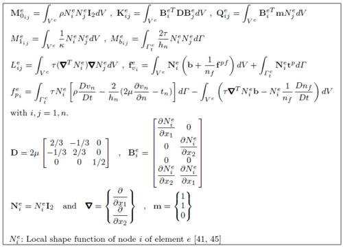
The different matrices and vectors in Eqs.(27) are shown in Box 1 for 2D problems.
Remark 3. The boundary terms of vector can be incorporated in the matrices of Eq.(27b). This, however, leads to a non symmetrical set of equations. For this reason we have chosen to compute these boundary terms iteratively within the incremental solution scheme.
Remark 4. Matrix in Eq.(27b) allows us to compute the pressure without the need of prescribing its value at the free surface. This eliminates the error introduced when the pressure is prescribed to zero in free boundaries, which may lead to considerable mass losses [20,45].
9 Incremental solution of the discretized equations
Eqs.(8) are solved in time with an implicit Newton-Raphson type iterative scheme [3,9,58,60]. The basic steps within a time interval are:
- Initialize variables: .
- Iteration loop: .
For each iteration.
Step 1. Compute the nodal velocity increments
From Eq.(27a), we deduce
|
|
(28a) |
with the momentum residual and the iteration matrix given by
|
|
(28b) |
with
|
|
(28c) |
Step 2. Update the velocities
|
|
(29a) |
|
|
(29b) |
Step 3. Compute the nodal pressures
From Eq.(27b) we obtain
|
|
(30a) |
with
|
|
(30b) |
Step 4. Update the coordinates of the fluid nodes and particles
|
|
(31a) |
|
|
(31b) |
Step 5. Compute the fluid volume fractions for each node via Eq.(2)
Step 6. Compute forces and torques on particles:
Step 7. Compute particle-to-fluid nodes: with computed by Eq.(18)
Step 8. Check convergence
Verify the following conditions:
|
|
(32) |
where and are prescribed error norms for the nodal velocities and the nodal pressures, respectively. In the examples solved in this work we have set .
If both conditions (32) are satisfied then make and proceed to the next time step.
Otherwise, make the iteration counter and repeat Steps 1–8.
Remark 5. In Eqs.([[#Step 1. Compute the nodal velocity increments |28]])–(32) denotes the values of a matrix or a vector computed using the nodal unknowns at time . In our work the derivatives and integrals in the iteration matrices and and the residual vector are computed on the discretized geometry at time (i.e. ) while the nodal force vectors and are computed on the current configuration at time . This is equivalent to using an updated Lagrangian formulation [3,12,44,59].
Remark 6. The tangent “bulk” stiffness matrix in the iteration matrix of Eq.(28b) accounts for the changes of the pressure due to the velocity. Including matrix in has proven to be essential for the fast convergence, mass preservation and overall accuracy of the iterative solution [11,45].
Remark 7. The parameter in () has the role of preventing the ill-conditioning of the iteration matrix for very large values of the speed of sound in the fluid that lead to a dominant role of the terms of the tangent bulk stiffness matrix . An adequate selection of also improves the overall accuracy of the numerical solution and the preservation of mass for large time steps. Details of the derivation of Eq.(28c) can be found in [45].
Remark 8. The iteration matrix in Eq.(28a) is an approximation of the exact tangent matrix in the updated Lagrangian formulation for a quasi/fully incompressible fluid [44]. The simplified form of used in this work has yielded very good results with convergence achieved for the nodal velocities and pressure in 3–4 iterations in all the problems analyzed.
Remark 9. The time step within a time interval has been chosen as where is the minimum characteristic distance of all elements in the mesh, with computed as explained in Section 6, is the maximum value of the modulus of the velocity of all nodes in the mesh and is the critical time step of all nodes approaching a solid boundary [45].
10 About the particle finite element method (PFEM)
10.1 The basis of the PFEM
Let us consider a domain containing fluid and solid subdomains. Each subdomain is characterized by a set of points, hereafter termed virtual particles. The virtual particles contain all the information for defining the geometry and the material and mechanical properties of the underlying subdomain. In the PFEM both subdomains are modelled using an updated Lagrangian formulation [3,44,59].
The solution steps within a time step in the PFEM are as follows:
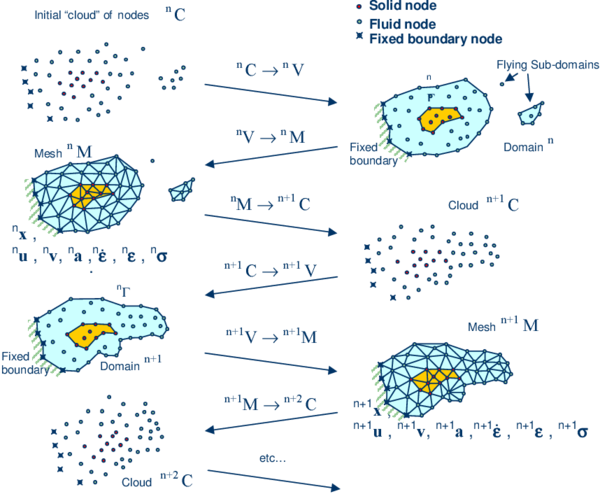
- The starting point at each time step is the cloud of points in the fluid and solid domains. For instance denotes the cloud at time (Figure 5).
- Identify the boundaries defining the analysis domain , as well as the subdomains in the fluid and the solid. This is an essential step as some boundaries (such as the free surface in fluids) may be severely distorted during the solution, including separation and re-entering of nodes. The Alpha Shape method [10] is used for the boundary definition. Clearly, the accuracy in the reconstruction of the boundaries depends on the number of points in the vicinity of each boundary and on the Alpha Shape parameter. In the problems solved in this work the Alpha Shape method has been implementation as described in [17,35].
- Discretize the the analysis domain with a finite element mesh We use an efficient mesh generation scheme based on an enhanced Delaunay tesselation [17,35].
- Solve the Lagrangian equations of motion for the overall continuum using the standard FEM. Compute the state variables in at the next (updated) configuration for : velocities, pressure and viscous stresses in the fluid and displacements, stresses and strains in the solid.
- Move the mesh nodes to a new position where n+1 denotes the time , in terms of the time increment size.
- Go back to step 1 and repeat the solution for the next time step to obtain .
|
| Figure 5: Sequence of steps in the PFEM to update a “cloud” of nodes representing a domain containing a fluid and a solid part (in darker shadow) from time () to time () |
Note that the key differences between the PFEM and the classical FEM are the remeshing technique and the identification of the domain boundary at each time step.
The CPU time required for meshing grows linearly with the number of nodes. As a general rule, meshing consumes for 3D problems around 15% of the total CPU time per time step [43].
Application of the PFEM in fluid and solid mechanics and in fluid-structure interaction problems can be found in [CaOnSu10,CaOnSu13,CrFrPe11,FrOnCa13,IdOnPi04,IdMaLiOn08,IdMiOn09a,IdOn10, Laetal08,Oliver07,Oliver09, Onetal04b,OnCeId06a,Onetal06c,Onetal08,Onetal10,Onetal11,OnCa13,OnFrCa14a,OnFrCa14b], as well in www.cimne.com/pfem.
10.2 Treatment of contact conditions
Known velocities at boundaries in the PFEM are prescribed in strong form to the boundary nodes. These nodes might belong to fixed external boundaries or to moving boundaries linked to the interacting solids. Surface tractions are applied to the Neumann part of the boundary, as usual in the FEM.
Contact between fluid particles and fixed boundaries is accounted for by adjusting the time step so that fluid nodes do not penetrate into the solid boundaries [45].
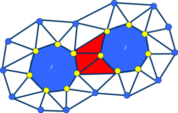
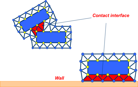
The contact between two large particles (and between two bodies, in general) is treated by introducing a layer of contact elements between the two interacting particles. This contact interface layer is automatically created during the mesh generation step by prescribing a minimum distance between two interacting particles. If the distance exceeds the minimum value then the generated elements are treated as fluid elements. Otherwise the elements are treated as contact elements where a relationship between the tangential and normal forces and the corresponding displacement is introduced [35,40,43] (Figure 6).
This algorithm allows us to model complex frictional contact conditions between two or more interacting bodies moving in water in an a simple manner. The algorithm has been used to model frictional contact situations between rigid and elastic solids in structural mechanics applications, such as soil/rock excavation problems [4,5]. The frictional contact algorithm described above has been extended by Oliver et al. [27,28] for analysis of metal cutting and machining problems.
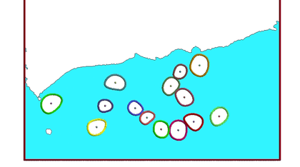
Figure 7 shows an example of the analysis with the PFEM of a collection of large particles submerged in a tank containing water in sloshing motion.
|
| Figure 7: PFEM results for the motion of large particles submerged in a tank containing water in sloshing motion |
10.3 Treatment of surface erosion
Prediction of bed erosion and sediment transport in open channel flows are important tasks in many areas of river and environmental engineering. Bed erosion can lead to instabilities of the river basin slopes. It can also undermine the foundation of bridge piles thereby favouring structural failure. Modeling of bed erosion is also relevant for predicting the evolution of surface material dragged in earth dams in overspill situations. Bed erosion is one of the main causes of environmental damage in floods.
Oñate et al. [36] have proposed an extension of the PFEM to model bed erosion. The erosion model is based on the frictional work at the bed surface originated by the shear stresses in the fluid.
The algorithm for modeling the erosion of soil/rock particles at the fluid bed is briefly the following:
- Compute at every point of the bed surface the tangential stress induced by the fluid motion.
- Compute the frictional work originated by the tangential stress at the bed surface.
- The onset of erosion at a bed point occurs when exceeds a critical threshold value .
- If at a bed node, then the node is detached from the bed region and it is allowed to move with the fluid flow. As a consequence, the mass of the patch of bed elements surrounding the bed node vanishes in the bed domain and it is transferred to the adjacent fluid node. This mass is subsequently transported with the fluid as an immersed macroscopic particle.
- Sediment deposition can be modeled by an inverse process to that described in the previous step. Hence, a suspended node adjacent to the bed surface with a velocity below a threshold value is attached to the bed surface.
Figure 8 shows an schematic view of the bed erosion algorithm described. Details of the algorithm can be found in [36].
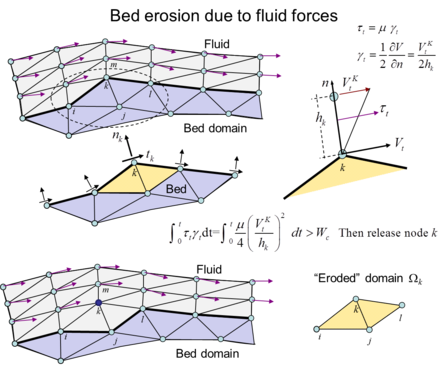
|
| Figure 8: Modeling of bed erosion with the PFEM. The mass of the eroded domain is assigned to the fluid node |
11 A nodal algorithm for transporting microscopic and macroscopic particles within a finite element mesh
The fact that in the PFEM a new mesh is regenerated at each time step allows us to make microscopic and macroscopic particles to be coincident with fluid nodes. An advantage of this procedure is that it provides an accurate definition of the particles at each time step which is useful for FSI problems.
The algorithm to compute the position of the particles using the nodal algorithm is as follows.
At each time step :
- Compute the converged value of the position of the fluid nodes () and the particles () using the algorithm of Section 9. The particles coinciding with fluid nodes () will typically move to a different position than that of the corresponding fluid nodes (Figure 9).
- Regenerate the mesh discretizing the fluid domain treating the position of the particles as fluid nodes and ignore the fluid nodes originally coinciding with the particles at .
- Interpolate the velocity of the fluid nodes at the position of the particles surrounding the fluid nodes.
The algorithm is schematically described in Figure 9.
Figures 10 show an example of the application of the nodal algorithm to the study of the motion of an individual particle within a rectangular domain filled with water. The correct end velocity for the individual particle is obtained as shown in Figure 10c. Figures 11–13 show other examples of application of the nodal algorithm to the motion of macro-particles in water containers.
Other examples of application of this algorithm are shown in the next section.
| (a) | (b) |
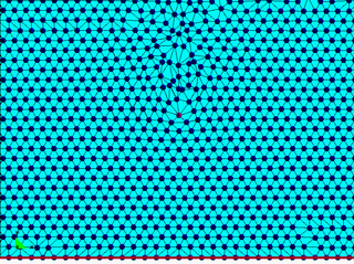
|
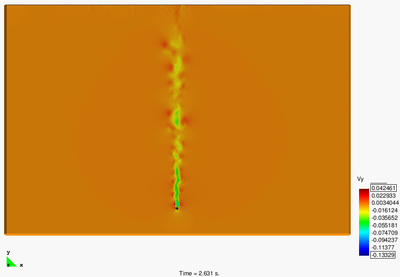
|
| (c) | |
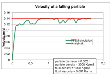
| |
| Figure 10: Cylindrical particles falling in a water container. 2D PFEM solution using the nodal algorithm for tracking the particle motion. (a) Mesh and particle at a certain instant. (b) Contours of the vertical velocity module. (c) Evolution of the vertical velocity of the particle until a steady state solution is found [6,15] | |
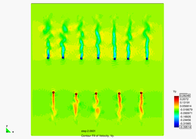
|
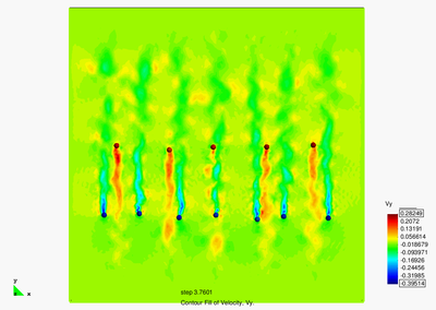
|
| Figure 11: Motion of ascending and descending particles of different density in a fluid domain. PFEM results using the nodal algorithm for tracking the particles motion | |
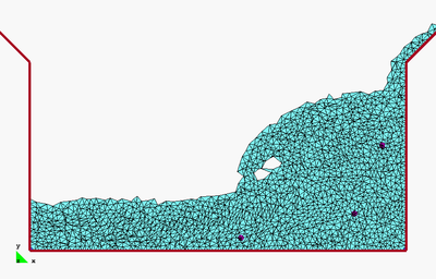
|
| Figure 12: Motion of three macroscopic particles in a water sloshing problem within a tank. PFEM results obtained using the nodal algorithm for particle tracking |
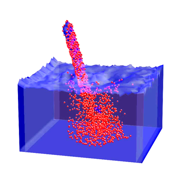
|
|
| Figure 13: PFEM analysis of the penetration of a collection of spherical (macroscopic) particles into a water container | |
12 Examples
We present the study of a several problems involving the transport of macroscopic and large particles in fluid flows. The problems are schematic representations of particulate flows occurring in practical problems of civil and environmental engineering and industrial problems.
Most problems studied have been solved with the PFEM using the nodal algorithm for the transport of macroscopic particles described in the previous section. An exception are the problems in Section 12.6 dealing with the vertical transport of spherical particles in a cylinder where the standard immersed approach for the transport macroparticles described in Sections 1–4 was used and the fluid equations were solved with an Eulerian flow solver implemented in the Kratos open-source software platform of CIMNE [24].
12.1 Erosion of a slope adjacent to the shore due to sea waves
Figure 14 shows a representative example of the progressive erosion of a soil mass adjacent to the shore due to sea waves and the subsequent falling into the sea of a 2D object representing the section of a lorry. The object has been modeled as a rigid solid. Note that the eroded soil particles accumulate at the sea bottom.
This example, although still quite simple and schematic, evidences the possibility of the PFEM for modeling FSSI problems involving soil erosion, free surface waves and rigid/deformable structures.
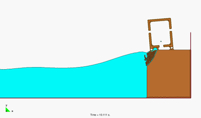
|
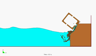
|
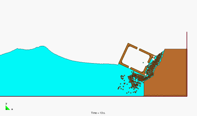
|
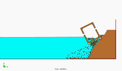
|
| Figure 14: Falling of a lorry into the sea by erosion of the underlying soil mass due to the action of waves | |
12.2 Landslide falling on houses
Figure 15 shows two instants of the 2D simulation with PFEM of the motion of a collection of macroscopic particles as they slide over an inclined wall and fall into a water container.
The PFEM is particularly suited for the modelling and simulation of landslides and their effect in the surrounding structures. Figure 16 shows an schematic 2D simulation of a landslide falling on two adjacent constructions. The landslide material has been assumed to behave as a pure viscoplastic material modelled as a non-Newtonian viscous incompressible fluid [57]. Other applications of the PFEM to the modelling of landslides can be found in [8,49].
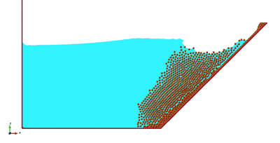
|
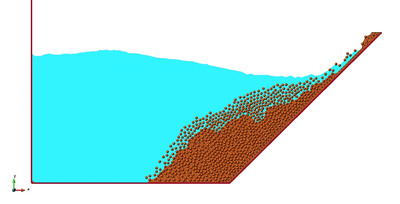
|
| Figure 15: Sliding of macroscopic particles over an inclined wall entering a container with water | |
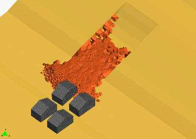
|
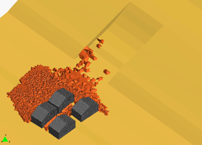
|
| Figure 16: 3D PFEM simulation of a landslide falling on four houses | |
12.3 Dragging of rocks by a water stream
Figure 17 shows the dragging of a collection of rocks modelled as large rigid particles of arbitrary shape by the action of a water stream. The particles move due to the action of the water forces on the particles computed by integrating the pressure and the viscous stresses in the elements surrounding each particle.
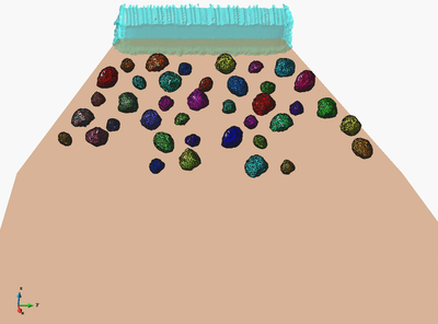
|
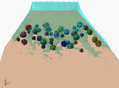
|
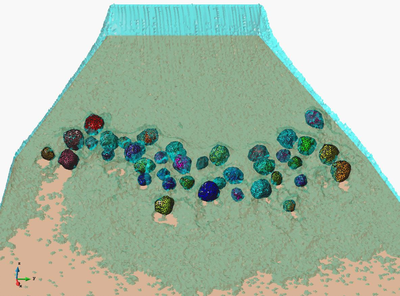
|
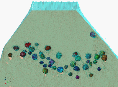
|
| Figure 17: 3D PFEM results for the dragging of a collection of large rocks by a water stream | |
12.4 Suction of cohesive material submerged in water
Figures 18 and 19 show two examples of the detachment, suction and transport of particles of a cohesive material submerged on water. Figure 18 shows how the particles detatch from the cohesive soil bed and are transported within the suctioning tube (modelled as a 2D problem). The last picture shows the erosion in the soil as the mixture of water and eroded particles falls down from within the tube and hits the soil surface due to a stop in the suction pressure.
Figure 19 shows a similar 3D problem. The suction in the tube erodes the surface of the soil bed in the right hand container. The mixture of water and eroded particles is transported to the adjacent containers.
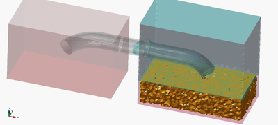
|
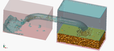
|
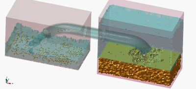
|
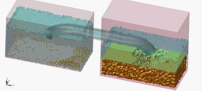
|
| Figure 19: 3D PFEM simulation of the detachment, suction and transport of submerged cohesive material from one recipient to another | |
12.5 Filling of a water container with particles
Figure 20 shows a 3D example of the filling of a cylindrical container with water containing macroscopic spherical particles. Water is allowed to exit the cylinder by a lateral hole while particles enter from two other holes at different height and fall down by gravity until they progressively fill the cylinder. The figures show different instants of the filling process.
12.6 Transport of spherical particles in a tube filled with water
The example in Figure 21 models the vertical transport of some 120.000 spherical particles to the surface of a tube filled with water and the subsequent deposition of the particles on the free water surface at the top of the tube. Particles move upwards within the tube due to a fluid velocity of 1 m/s. The average size of the particles radius is 2 mm and their density is 2300 Kg/m. Particles move vertically until they reach the top of the fluid domain and accumulate there due to the combined effect of their weight and the effect of the interaction force from the fluid. Figure 21 shows two instants of the particles ascending process. The accumulation of particles in the water free surface at the top of the tube is clearly seen.
Figure 22 shows the interaction of eigth jets of ascending air bubbles with 200.000 spherical solid particles that fall down within a cylinder filled with water.
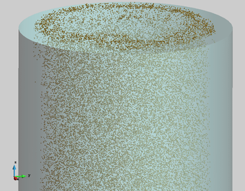
|
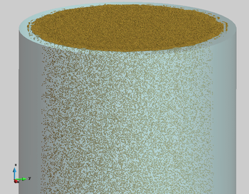 ] ]
|
| Figure 21: Transport of spherical macroparticles up to the free surface of a tube filled with water. Particles move up with a prescribed velocity until they accumulate on the free surface. Results obtained with a coupled DEM-Eulerian CFD code [24] | |
| (a) | (b) |
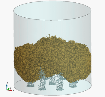
|
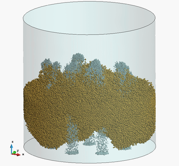
|
| (c) | (d) |
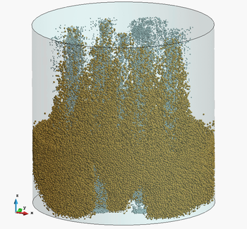
|
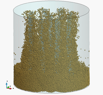
|
| Figure 22: Interaction of eight jets of ascending air bubbles with a thick layer of 200.000 spherical particles that fall down within a cylinder filled with water. Numerical results obtained with a coupled DEM-Eulerian CFD code [24] | |
12.7 Dragging of large objects and small particles in a tsunami type flow
The last example is the dragging of cars, barrels and debris (modelled as macroscopic particles) by a water stream that flows over a vertical wall. The problem represents an schematic study of a real situation corresponding to the tsunami in Fukushima (Japan) on March 2011 (Figure 23). Figures 24 show two snapshots of the PFEM solution of this complex problem.
|
| Figure 23: Dragging of cars and large and small objects in the Fukushima tsunami (Japan) |

|
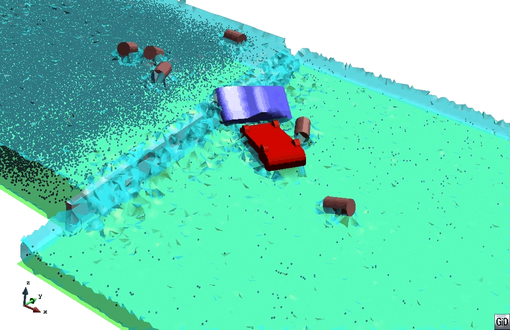
|
| Figure 24: Dragging of large objects and macroscopic particles in a tsunami type flow passing over a vertical wall. 3D PFEM results |
13 Concluding remarks
We have presented a Lagrangian numerical technique for analysis of flows incorporating physical particles of different sizes. The numerical approach is based on the Particle Finite Element Method (PFEM) and a stabilized Lagrangian mixed velocity-pressure formulation. The examples presented in the paper evidence the possibilities of the PFEM for analysis of practical multiscale particulate flows in industrial and environmental problems.
Acknowledgements
This research was supported by the Advanced Grant project SAFECON of the European Research Council.
References
[1] Anderson T, Jackson R. Fluid mechanical description of fluidized beds: equation of motion. Industrial & Engineering Chemical Fundamentals, 6(4):527–539
[2] Avci B, Wriggers P, (2012) A DEM-FEM coupling approach for the direct numerical simulation of 3D particulate flows. Journal of Applied Mechanics, 79(1), 7 pages
[3] T. Belytschko, W.K. Liu, B. Moran, Non linear finite element for continua and structures, 2d Edition, Wiley, 2013.
[4] Carbonell JM, Oñate E, Suárez B (2010) Modeling of ground excavation with the Particle Finite Element Method. Journal of Engineering Mechanics (ASCE) 136(4):455–463
[5] Carbonell JM, Oñate E, Suárez B (2013) Modelling of tunnelling processes and cutting tool wear with the Particle Finite Element Method (PFEM). Accepted in Comput. Mech. (2013) DOI:10.1007/s00466-013-0835-x
[6] Clift R, Grace JR, Weber ME (1978) Bubbles, drops and particles. Academic Press, New York
[7] Coussy O (2004) Poromechanics. Wiley
[8] Cremonesi M, Frangi A, Perego U (2011) A Lagrangian finite element approach for the simulation of water-waves induced by landslides. Computers & Structures 89:1086–1093
[9] Donea J, Huerta A (2003) Finite element method for flow problems. J. Wiley
[10] Edelsbrunner H, Mucke EP (1999) Three dimensional alpha shapes. ACM Trans. Graphics 13:43–72
[11] Franci A, Oñate E, Carbonell JM (2013) On the effect of the tangent bulk stiffness matrix in the analysis of free surface Lagrangian flows using PFEM. Research Report CIMNE PI402
[12] Franci A, Oñate E, Carbonell JM (2014b) Unified updated Lagrangian formulation for fluid-structure interaction problems. Research Report CIMNE PI404
[13] Gidaspow D (1994) Multiphase flow and fluidization. Continuum and Kinetic Theory Description, Academic Press, 467 pages
[14] Healy DP, Young DB (2005) Full Lagrangian method for calculating particle concentration field in dilute gas-particle flows. Proc. Roy. Soc., London A: Mathematical, Physical and Engineering Sciences, 461(2059):2197–2225
[15] Heider A, Levespiel O (1989) Drag coefficient and terminal velocity of spherical and nonspherical particles. Powder Technol. 58:63–70
[16] Hilton J, Cleary P (2013) Dust modelling using a combined CFD and discrete element formulation. Int. J. Num. Meth. Fluids, 72(5):528-549
[17] Idelsohn SR, Oñate E, Del Pin F (2004) The particle finite element method: a powerful tool to solve incompressible flows with free-surfaces and breaking waves. Int. Journal for Numerical Methods in Engineering, 61(7):964–989
[18] Idelsohn SR, Marti J, Limache A, Oñate E (2008) Unified Lagrangian formulation for elastic solids and incompressible fluids: Application to fluid-structure interaction problems via the PFEM. Comput Methods Appl Mech Engrg. 197:1762–1776
[19] Idelsohn SR, Mier-Torrecilla M, Oñate E (2009) Multi-fluid flows with the Particle Finite Element Method. Comput Methods Appl Mech Engrg. 198:2750–2767
[20] Idelsohn SR, Oñate E (2010) The challenge of mass conservation in the solution of free-surface flows with the fractional-step method: Problems and solutions. Int. J. Numer. Meth. Biomed. Engng. 26:1313–-1330
[21] Jajcevic D, Siegmann E, Radeke C, Khinast JG (2013) Large-scale CFD-DEM simulations of fluidized granular systems. Chemical Engineering Science, 98:298–310
[22] Jackson R (2000), The dynamics of fluidized particles. Cambridge Monographs on Mechanics, Cambridge Univ. Press
[23] Kafui DK, Thornton C, Adams MJ (2002) Discrete particle-continuum fluid modelling of gas-solid fluidised beds. Chemical Engng. Science, 57(13):2395–2410
[24] Kratos (2014) Open source software platform for multiphysics computations. CIMNE, Barcelona, www.cimne.com/kratos
[25] Larese A, Rossi R, Oñate E, Idelsohn SR (2008) Validation of the Particle Finite Element Method (PFEM) for simulation of free surface flows. Engineering Computations 25(4):385–425
[26] Liu SH, Sun DA (2002). Simulating the collapse of unsaturated soil by DEM. Int. J. Num. Anal. Meth. in Geomechanics, 26:633–646
[27] Oliver X, Cante JC, Weyler R, González C, Hernández J (2007) Particle finite element methods in solid mechanics problems. In: Oñate E, Owen R (Eds) Computational Plasticity. Springer, Berlin, pp 87–103
[28] Oliver X, Hartmann S, Cante JC, Wyler R, Hernández J (2009) A contact domain method for large deformation frictional contact problems. Part 1: theoretical basis. Comput Methods Appl Mech Eng 198:2591–2606
[29] Oñate E (1998) Derivation of stabilized equations for advective-diffusive transport and fluid flow problems. Comput. Meth. Appl. Mech. Engng. 151:233–267
[30] Oñate E (2000) A stabilized finite element method for incompressible viscous flows using a finite increment calculus formulation. Comput Methods Appl Mech Engrg. 182(1–2):355–370
[31] Oñate E, García J (2001) A finite element method for fluid-structure interaction with surface waves using a finite calculus formulation. Comput. Meth. Appl. Mech. Engrg. 191:635–660
[32] Oñate E (2003) Multiscale computational analysis in mechanics using finite calculus: an introduction. Comput. Meth. Appl. Mech. Engrg. 192(28-30):3043–3059
[33] Oñate E (2004) Possibilities of finite calculus in computational mechanics. Int. J. Num. Meth. Engng. 60(1):255–281
[34] Oñate E, Rojek J, (2004b) Combination of discrete element and finite element methods for dynamic analysis of geomechanics problems. Comput. Meth. Appl. Mech. Engrg. 193:3087–3128
[35] Oñate E, Idelsohn SR, Del Pin F, Aubry R (2004c) The particle finite element method. An overview. Int. J. Comput. Methods 1(2):267–307
[36] Oñate E, Celigueta MA, Idelsohn SR (2006a) Modeling bed erosion in free surface flows by the Particle Finite Element Method, Acta Geotechnia 1(4):237–252
[37] Oñate E, Valls A, García J (2006b) FIC/FEM formulation with matrix stabilizing terms for incompressible flows at low and high Reynold's numbers. Computational Mechanics 38 (4-5):440–455
[38] Oñate E, García J, Idelsohn SR, Del Pin F (2006c) FIC formulations for finite element analysis of incompressible flows. Eulerian, ALE and Lagrangian approaches. Comput. Meth. Appl. Mech. Engng. 195(23-24):3001–3037
[39] Oñate E, Valls A, García J (2007) Computation of turbulent flows using a finite calculus-finite element formulation. Int. J. Numer. Meth. Engng. 54:609–637
[40] Oñate E, Idelsohn SR, Celigueta MA, Rossi R (2008) Advances in the particle finite element method for the analysis of fluid-multibody interaction and bed erosion in free surface flows. Comput. Meth. Appl. Mech. Engng. 197(19-20):1777–1800
[41] Oñate E (2009), Structural analysis with the finite element method. Linear statics. Volume 1. Basis and Solids. CIMNE-Springer
[42] Oñate E, Rossi R, Idelsohn SR, Butler K (2010) Melting and spread of polymers in fire with the particle finite element method. Int. J. Numerical Methods in Engineering, 81(8):1046–1072
[43] Oñate E, Celigueta MA, Idelsohn SR, Salazar F, Suárez B (2011) Possibilities of the particle finite element method for fluid-soil-structure interaction problems. Computational Mechanics, 48(3):307–318.
[44] Oñate E, Carbonell JM (2013) Updated Lagrangian finite element formulation for quasi and fully incompressible fluids. Research Report PI393, CIMNE. Submitted to Comput. Mechanics
[45] Oñate E, Franci A, Carbonell JM (2014) Lagrangian formulation for finite element analysis of quasi-incompressible fluids with reduced mass losses. Accepted for publication in Int. J. Num. Meth. in Fluids, 74(10):699–-731
[46] Oñate E, Franci A, Carbonell JM (2014b) A Particle Finite Element Method (PFEM) for analysis of industrial forming processes. Accepted for publication in Comput. Mechanics
[47] Patankar NA, Joseph DD (2001) Lagrangian numerical simulation of particulate flows. Int. J. Multiphase Flow, 27:1685–1706
[48] Ryzhakov P, Oñate E, Rossi R, Idelsohn SR (2012) Improving mass conservation in simulation of incompressible flows. Int. J. Numer. Meth. Engng. 90(12):1435–1451
[49] Salazar F, Oñate E, Morán R (2012) Modelación numérica del deslizamiento de ladeu en embalses mediante el método de partículos y elementos finitos (PFEM). Rev. Int. Meth. Num. Cal. Dis. Ing., 28(2):112–123
[50] Shamy UE, Zeghal M (2005) Coupled continuum–discrete model for saturated granular soils. J. Engineering Mechanics (ASCE), 131(4):413–-426
[51] Sommerfeld M, van Wachen B, Oliemans R (Eds) (2008) Best practice guideliens for computational fluid dynamics of dispersed multiphase flows. European Research Community on Flow, Turbulence and Combustion (ERCOFTAC), Imperial College London.
[52] Tang B, Li JF, Wang TS (2009) Some improvements on free surface simulation by the particle finite element method. Int. J. Num. Methods in Fluids, 60(9):1032–-1054
[53] van Wachen B, Oliveira ES (2010) An immersed boundary method for interacting particles. ERCOFTAC Bulletin 82, 17–22 March 2010
[54] Wang X, Zhang LT, Liu WK (2009) On computational issues of the immersed finite element method. J. Comp. Physics, 228:2535–2551
[55] Li X, Chu X, Sheng DC (2007) A saturated discrete particle model and characteristic-based SPH method in granular materials. Int. J. Numer. Meth. Engng., 72:858–882
[56] Zhang LT, Gerstenberg A, Wang X, Liu WK (2004) Immersed finite element method. Comput. Meth. Appl. Mech. Engrg., 193(21-22):2051–2067
[57] Zienkiewicz OC, Jain PC, Oñate E (1978) Flow of solids during forming and extrusion: some aspects of numerical solutions. Int. J. Solids Struct., 14:15–38
[58] Zienkiewicz OC, Taylor RL, Zhu JZ (2005) The finite element method. The basis. 6th Ed., Elsevier
[59] Zienkiewicz OC, Taylor RL (2005) The finite element method for solid and structural mechanics. 6th Ed., Elsevier
[60] Zienkiewicz OC, Taylor RL, Nithiarasu P (2005) The finite element method for fluid dynamics. 6th Ed., Elsevier
[61] Zohdi T (2007) An introduction to modelling and simulation of particulate flows. SIAM, Computational Science and Engineering
[62] Zohdi T, Wriggers P (2007) Computation of strongly coupled multifield interaction in particle-fluid systems. Comput. Meth. Appl. Mech. Engng., 196:3927–3950Document information
Published on 01/01/2014
DOI: 10.1007/s40571-014-0012-9
Licence: CC BY-NC-SA license
Share this document
claim authorship
Are you one of the authors of this document?
