(Created page with "==Abstract== This paper presents an optimal design of three dimensional multi-story reinforced concrete structures using recently developed meta-heuristic algorithms, namely;...") |
m (Scipediacontent moved page Draft Content 514306669 to Kaveh Behnam 2013a) |
(No difference)
| |
Latest revision as of 14:56, 6 October 2016
Abstract
This paper presents an optimal design of three dimensional multi-story reinforced concrete structures using recently developed meta-heuristic algorithms, namely; the charged system search and the enhanced charged system search. The design is based on the ACI 318-05 code and loadings are based on ASCE7-05. Analysis of the structures is performed by the standard stiffness method. All members are subjected to biaxial moments and axial loads. Pre-determined sections are assumed for beams and columns, and the corresponding interaction curves are utilized to check whether the selected section for each member is acceptable. The objective function is taken as the weight of the structure, and constraints consist of the slenderness of compression members, the maximum allowable drift of the structure and the natural frequency of the structure. It should be mentioned that second order effects are also considered and that the end moments of the columns are magnified when needed.
First, a 7-story frame with 3 spans is considered and optimized. Then, a sensitivity analysis is performed by optimal design of nine frames having 3 stories and 2 spans. In each story, different span lengths and loading conditions are assumed, and the results are compared.
Keywords
Optimization ; Reinforced concrete ; Three dimensional frames ; Natural frequency ; Charged system search ; Enhanced charged system search
1. Introduction
Many large reinforced concrete structures have been designed and constructed worldwide in the past century. Before the development of computers, analysis and design steps were done by simplified approaches, mainly by trial and error. After the arrival of computers, some prominent software, such as ETABS and SAP from Computers and Structures Inc., helped engineers to analyze and design these structures. These software tried to optimize their results via trial and error. However, these design methods should further be improved by addition of powerful optimization systems to these software.
Different methods have been used for the optimal design of RC structures over the past two decades. Fadaee and Grierson [1] optimized the cost of 3D skeletal structures using optimality criteria. Balling and Yao [2] optimized 3D frames with a multi-level method by decomposing the problem into a system optimization problem and a series of individual member optimization problems, and Rajeev and Krishnamoorthy [3] applied a Simple Genetic Algorithm (SGA) to the cost optimization of 2D frames. In this paper, we perform the design process of a three dimensional RC structure by utilizing a robust meta-heuristic algorithm known as the Charged System Search (CSS) and an enhanced version of this method [4] and [5] .
The CSS algorithm is based on Coulomb and Gauss laws from Physics and Newton laws from Mechanics. A number of charged particles are considered that have coordinates equivalent to the variables of structures and have the shape of a sphere with a uniform volume charge. The values assumed for these variables create the coordinates of each particle. Each of these particles has a charge proportional to the fitness of the particle. In other words, the better the fitness, the more the charge of the particle. These particles can attract each other in such a way that a better particle certainly attracts a worse particle, but a worse particle perhaps attracts the better particle. The force applied between the particles and the paths of particle motion are obtained from Coulomb and Gauss laws and Newton laws, respectively. Therefore, a force is applied to each particle and this force causes a displacement such that all particles are located in new positions. In this way, the optimization process in the CSS is performed.
2. Optimum design of three dimensional RC structures
2.1. Design variables
In this study, the sections used for beams or column members are predetermined as 13 sizes for each one. Beam sections have a rectangular shape with dimensions of , by a step of 50 mm in each direction, and column sections are square with dimensions of , by a step of 50 mm. Each size of the beam and column sections consists of 5 sections with varying numbers of tension and compression rebar. The sizes of the rebars used in the sections are D10–D30, by a step of 5. Table 1 and Table 2 present the sections used for members in the analysis and design process.
| Beam sections | Height | Width | Type 1 | Type 2 | Type 3 | Type 4 | Type 5 | |||||
|---|---|---|---|---|---|---|---|---|---|---|---|---|
| T-rebar | C-rebar | T-rebar | C-rebar | T-rebar | C-rebar | T-rebar | C-rebar | T-rebar | C-rebar | |||
| 1 | 200 | 150 | 3-D10 | 0-D10 | 4-D10 | 0-D10 | 5-D10 | 0-D10 | 5-D10 | 3-D10 | 5-D10 | 4-D10 |
| 2 | 250 | 200 | 4-D10 | 0-D10 | 5-D10 | 0-D10 | 6-D10 | 0-D10 | 6-D10 | 4-D10 | 6-D10 | 5-D10 |
| 3 | 300 | 250 | 5-D10 | 0-D10 | 6-D10 | 0-D10 | 7-D10 | 0-D10 | 7-D10 | 4-D10 | 7-D10 | 5-D10 |
| 4 | 350 | 300 | 4-D15 | 0-D15 | 5-D15 | 0-D15 | 6-D15 | 0-D15 | 6-D15 | 3-D15 | 6-D15 | 4-D15 |
| 5 | 400 | 350 | 5-D15 | 0-D15 | 6-D15 | 0-D15 | 7-D15 | 0-D15 | 7-D15 | 4-D15 | 7-D15 | 5-D15 |
| 6 | 450 | 350 | 6-D15 | 0-D15 | 7-D15 | 0-D15 | 8-D15 | 0-D15 | 8-D15 | 5-D15 | 8-D15 | 6-D15 |
| 7 | 500 | 350 | 7-D15 | 0-D15 | 8-D15 | 0-D15 | 9-D15 | 0-D15 | 9-D15 | 6-D15 | 9-D15 | 7-D15 |
| 8 | 550 | 400 | 5-D20 | 0-D20 | 6-D20 | 0-D20 | 7-D20 | 0-D20 | 7-D20 | 4-D20 | 7-D20 | 5-D20 |
| 9 | 600 | 400 | 6-D20 | 0-D20 | 7-D20 | 0-D20 | 8-D20 | 0-D20 | 8-D20 | 5-D20 | 8-D20 | 6-D20 |
| 10 | 650 | 400 | 7-D20 | 0-D20 | 8-D20 | 0-D20 | 9-D20 | 0-D20 | 9-D20 | 6-D20 | 9-D20 | 7-D20 |
| 11 | 700 | 450 | 7-D25 | 0-D25 | 8-D25 | 0-D25 | 9-D25 | 0-D25 | 9-D25 | 6-D25 | 9-D25 | 7-D25 |
| 12 | 750 | 450 | 7-D25 | 0-D25 | 8-D25 | 0-D25 | 9-D25 | 0-D25 | 9-D25 | 6-D25 | 9-D25 | 7-D25 |
| 13 | 800 | 450 | 7-D30 | 0-D30 | 8-D30 | 0-D30 | 9-D30 | 0-D30 | 9-D30 | 6-D30 | 9-D30 | 7-D30 |
| Column sections | Height | Width | Type 1 | Type 2 | Type 3 | Type 4 | Type 5 | |||||
|---|---|---|---|---|---|---|---|---|---|---|---|---|
| T-rebar | C-rebar | T-rebar | C-rebar | T-rebar | C-rebar | T-rebar | C-rebar | T-rebar | C-rebar | |||
| 1 | 200 | 200 | 3-D10 | 3-D10 | 4-D10 | 4-D10 | 5-D10 | 5-D10 | 6-D10 | 6-D10 | 7-D10 | 7-D10 |
| 2 | 250 | 250 | 4-D15 | 4-D15 | 5-D15 | 5-D15 | 6-D15 | 6-D15 | 7-D15 | 7-D15 | 8-D15 | 8-D15 |
| 3 | 300 | 300 | 5-D15 | 5-D15 | 6-D15 | 6-D15 | 7-D15 | 7-D15 | 8-D15 | 8-D15 | 9-D15 | 9-D15 |
| 4 | 350 | 350 | 4-D20 | 4-D20 | 5-D20 | 5-D20 | 6-D20 | 6-D20 | 7-D20 | 7-D20 | 7-D20 | 7-D20 |
| 5 | 400 | 400 | 5-D20 | 5-D20 | 6-D20 | 6-D20 | 7-D20 | 7-D20 | 8-D20 | 8-D20 | 9-D20 | 9-D20 |
| 6 | 450 | 450 | 6-D25 | 6-D25 | 7-D25 | 7-D25 | 8-D25 | 8-D25 | 9-D25 | 9-D25 | 10-D25 | 10-D25 |
| 7 | 500 | 500 | 7-D25 | 7-D25 | 8-D25 | 8-D25 | 9-D25 | 9-D25 | 10-D25 | 10-D25 | 11-D25 | 11-D25 |
| 8 | 550 | 550 | 5-D25 | 5-D25 | 6-D25 | 6-D25 | 7-D25 | 7-D25 | 8-D25 | 8-D25 | 9-D25 | 9-D25 |
| 9 | 600 | 600 | 6-D25 | 6-D25 | 7-D25 | 7-D25 | 8-D25 | 8-D25 | 9-D25 | 9-D25 | 10-D25 | 10-D25 |
| 10 | 650 | 650 | 7-D30 | 7-D30 | 8-D30 | 8-D30 | 9-D30 | 9-D30 | 10-D30 | 10-D30 | 11-D30 | 11-D30 |
| 11 | 700 | 700 | 7-D30 | 7-D30 | 8-D30 | 8-D30 | 9-D30 | 9-D30 | 10-D30 | 10-D30 | 11-D30 | 11-D30 |
| 12 | 750 | 750 | 7-D30 | 7-D30 | 8-D30 | 8-D30 | 9-D30 | 9-D30 | 10-D30 | 10-D30 | 11-D30 | 11-D30 |
| 13 | 800 | 800 | 8-D30 | 8-D30 | 9-D30 | 9-D30 | 10-D30 | 10-D30 | 11-D30 | 11-D30 | 12-D30 | 12-D30 |
2.2. Loading of the structure and load combinations
In this work, the assumed dead and live loads on each floor are and , respectively. Also, lateral loads are calculated on the basis of the ASCE7-05 code [6] , by assuming that the site class of the structure is , and and are 0.75 and 0.3, respectively. The ACI 318-05 code [7] for strength design suggests the following load cases:
|
|
( 1) |
2.3. Analysis of the structure
To determine the forces and moments in the members after selecting the section for each member, the structure is analyzed. This analysis is performed using the finite element method. In RC frames, in order to consider the effect of cracking, the moment of inertia and the area of the cross section for each member are calculated using the following relationships:
|
|
( 2) |
and are gross area and gross moment of inertia of the section of the beam or column, respectively [8] . The ACI 318-05 code provides the elastic modulus of the concrete as in MPa. The analysis of the frame consists of controlling the slenderness of the columns, and in case a section is recognized to be slender, magnified bending is considered for that column.
2.3.1. Slenderness
According to the ACI 318-05 code [7] , for compression members not braced sideways, the slenderness effects can be neglected, when . In this relation, is the effective length factor for compression members, is the unsupported length of the compression member, and is the radius of gyration of the cross section of a compression member.
The effective length factor of a column denoted by depends on the ratio of the stiffness of the columns to the stiffness of beams connected at the end of the compression member. This ratio at the end of a compression member can be expressed as:
|
|
( 3) |
where is the moment of inertia considering the cracked section, is the modulus of elasticity, and is the length of the beams and columns. Indices and refer to beams and columns connected to the ends of a column, respectively.
After calculating for the ends of each compressive member, the mean value of these values, , is obtained, and the coefficient of the effective length of the compression member, , is calculated using the following relationships:
|
|
( 4) |
For a fixed support, we have . The radius of gyration is calculated as .
For a slender column, the magnified bending moment can be calculated as:
|
|
( 6) |
where is the bending moment generated by the gravity load, is due to lateral load and is the moment magnification factor for frames not braced sideways. After determining the magnified moment separately for each end of a column, the biggest one is used to design the column. The calculation of the magnification factor, , is as follows:
|
|
( 7) |
In this relationship, is the sum of the vertical loads in each story and is the sum of the critical buckling loads of the columns in each story that resists lateral loads. is obtained from the following relationship:
|
|
( 8) |
2.3.2. Free vibration and natural period of structure
One important parameter in the design of a structure is its natural period. The value of the natural period is very effective in the behavior of a structure. A structure with higher natural period behaves more elastically. Also, in the reaction spectrum, a bigger period causes less spectral response acceleration. Therefore, it is very important to control this parameter. In this paper, frequency constraints are considered to control this parameter. For both structures, first, similar frames are modelled in ETABS software and design steps are performed to have acceptable but not necessarily optimum members, using similar pre-determined sections utilized in the paper. Then by modal analysis, the fundamental period of each structure is determined, and the coefficient of 1.2 is multiplied by the calculated periods to increase the flexibility of the structures and reduce the induced seismic loads. Thus, a period of 0.8 (s) or more is acceptable for the design of 7-story frames and 0.5 (s) is suitable for 3-story structures.
2.4. Design considerations
In this work, for each pre-determined section, the interaction curve is traced accurately as a function in the main program. For these curves, reduction factors are applied. This operation is performed by changing the compression area of each section from 0 to the height of the section, and and are calculated:
|
|
( 9) |
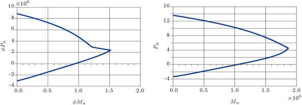
where is the width of the cross section; is the area of compressive bars; is the area of tensile bars; is the yield strength of compressive bars; is the stress value in compressive bars; is the distance of the center of compressive bars from the furthest compression fiber of the section; is the distance between the plastic neutral axis and centroid of tensile bars; is the depth of the equivalent rectangular stress block; is the eccentricity of the axial load from the plastic neutral axis; is the eccentricity of the axial load from the centroid of the tensile bars; is the nominal axial strength and is the nominal flexural strength of the section. A sample of these interaction curves is presented in Figure 1 .
|
|
|
Figure 1. The and interaction curves for section B11-type 5. |
The eccentricity of the members in and directions is calculated in the analysis and used to find the ultimate capacity of each section. Biaxial bending is considered for the members using the MacGregor method. This method replaces the biaxial eccentricities with an equivalent uniaxial eccentricity, and members are designed with equivalent uniaxial moments and axial forces as described in the following.
MacGregor suggested that sections designed for biaxial bending should be proportioned on the basis of the required axial load acting at eccentricity larger than either of the required values, and . For greater than, or equal to, , value should be taken as:
|
|
( 13) |
where in the above equation is calculated as:
|
|
( 14a) |
where is the gross area of the cross section; and are column cross section dimensions along the - and -axis, respectively. If , then, and terms, as well as subscripts in Eq. (5) , are transposed. Hence, a section is checked for the required load, , acting at eccentricity about one of the principal axes of the rectangular section.
The maximum ultimate axial forces and moments that are achieved from the above analysis are compared to the ultimate capacity of each member’s section. If the achieved forces are less than ultimate capacity, the member section is accepted. If one of them is greater than the capacity, the selected section will be unacceptable and the objective function should be fined for this member.
It should be mentioned that, in this paper, the analysis of a structure is based on six degrees of freedom per node, and shear forces and torsions are calculated during the analysis. Therefore, all members, including beams and columns, are checked for shear capacity by considering their dimensions. However, in the process of design, the stirrups are disregarded for the sake of simplicity of optimization.
3. A brief description of the charged system search
The charged system search is an approach based on some principals from Physics and Mechanics. Coulomb and Gauss laws from electrostatics are used for determining the value of attracting forces between Charged Particles (CPs). Newton laws are used for determination of the displacement of each CP. For more details, readers may refer to [4] and [5] . In this section, some essential equations from the CSS method used for optimization are explained.
- The value of charge magnitude for each particle is defined as:
|
|
( 15) |
where and are the best and the worst fitness of all the particles and represents the fitness of agent .
- The distance between each pair of particles is defined as:
|
|
( 16) |
where and are the positions of the th and th CPs, respectively, is the position of the best current CP and is a small positive number to avoid singularities.
- The probability of moving each CP toward other CPs is determined by the following conditional equation:
|
|
( 17) |
- The attracting force between each charged particle is defined as:
|
|
( 18) |
where is the resultant force affecting the th CP.
- The new position and velocity of each CP is obtained as:
|
|
( 19) |
where and are two random numbers uniformly distributed in the range (0, 1). is the mass of the CPs, which is equal to in this paper. is the time step, and it is set to 1. is the acceleration coefficient, and is the velocity coefficient. These coefficients are defined as:
|
|
( 21) |
4. Enhanced charged system search
One of the assumptions of every meta-heuristic algorithm is that the time alters discretely. This means that all alterations in space–time are performed when all agents have created their solutions. For example, in the CSS algorithm, when the calculations of the amount of forces are completed for all CP, the new locations of agents are determined. Also, Charged Memory (CM) updating is fulfilled after moving all CPs to their new locations. All these conform to the discrete time concept. In the optimization problems, this is known as iteration. In other words, the modification of space–time for the multi-agent algorithms is often performed when iteration is completed and the new iteration has not yet started. This assumption is ignored in the enhanced CSS algorithm. In the enhanced CSS, time changes continuously and after creating just one solution, all updating processes are performed [5] . Using the enhanced CSS, the new position of each agent can affect the moving process of subsequent CPs, while, in the standard CSS, unless an iteration is completed, the new positions are not utilized.
Here, the fly to boundary method is utilized for the discrete optimum design of RC structures [9] .
5. Objective function
The purpose of optimization is to design a structure that resists the applied loads; the members have a minimum possible size to reduce the structure’s weight. It is obvious that when the weight of the structure reduces, the lateral forces also reduce, and this results in a reduction in the section size of the structure. In this paper, the objective function of the optimization is considered to be the weight function of the structure. There are some reasons for choosing a weight function instead of a cost function, as explained in the following:
- Material and labor costs are varied from one country to another and, therefore, the use of relative cost as an objective function would be deeply dependent on the location at which these structures were built.
- In comparison to steel structures, member sections of the RC structures have larger dimensions, and this is one weaknesses of this kind of structure. In this paper, the aim is to reduce the dimensions of member sections as far as possible. Also, the higher cost of steel compared to that of concrete leads the algorithm to select larger sections with less rebar, which is not ideal. In fact, the weight function looks for suitable sections without giving priority to a particular material.
- The weight function of the structure is as follows:
|
|
( 22) |
where:
- = Length of the members (m);
- = Total area of the reinforcing bars for each section (m2 );
- = Density of concrete (N/m3 );
- = Density of rebar (N/m3 );
- = Externally applied moment and axial force of the members, respectively;
- = Nominal flexural and axial strength of the members, respectively;
- = Natural period of the structure (s)
- = Penalty coefficient for violating the strength of the member, and assumed as 1.5.
- = Penalty coefficient for violating the slenderness constraint of columns. This is assumed as 1.4.
- = Penalty coefficient for violating the natural period of structure. This is assumed as 1.3.
- = Penalty coefficient for violating the allowed story drift of the structure and it is assumed as 1.2.
It is noticeable that the penalty coefficients are indirectly related to the weight of the structure. This is because the larger weight causes bigger cross section dimensions. Thus, for example, when one section violates the strength of the member or slenderness constraints by magnifying its weight, the dimension of the section will become bigger, hence, preventing this violation. These magnifying factors are and . Also, for the natural period and story drift, and affect the entire weight of the structure, respectively, since these parameters are related to the enlargement of all members. From an optimization point of view, these coefficients make the value of the objective function worse when the selected variables are not suitable for the optimization problem and the related CP is ranked inferior. Therefore, the CPs without violations come up in ranking and the optimization process stays on the right path.
6. Optimum design of RC structures
The design process begins by input data. All data for the structure, such as joint coordinates, pairs of joints forming members, member lengths, loading on members and joints, and input of materials, such as yield stress of concrete and steel and concrete compressive characteristic strength, are prepared in a Microsoft Excel file and imported at the beginning of the program. The design process via the CSS algorithm consists of three levels as follows [4] :
Level 1: Initialization
Step 1: Select the random values for particles. In this paper, the number of CPs is set to 20. The number of variables is equal to the number of members, including columns and beams, which are selected randomly between the predetermined sections for each group. In this way, the initial positions of the CPs are defined.
Step 2: In this step, for each CP, conditional inequalities for the objective function are checked, and if every condition is satisfied, the value of the objective function is calculated. Otherwise, the objective function is fined and then the CPs are sorted in an increasing order.
Step 3: The CMS number of the first CPs and the related values of the objective function are stored in the charged memory (CM). CMS is chosen to be 5 in this article.
Level 2: Search
Step 1: In this step, the distance between CPs and the charge of the CPs are calculated, and then, the probability of moving CPs toward others and attracting forces for CPs is determined.
Step 2: After determination of attracting forces, the new position and new velocity of each CP are determined.
Step 3: Some particles’ new positions violate the boundaries. The CSS algorithm corrects their position using the harmony search based handling approach [4] and [10] .
Step 4: This step is similar to step 2 of level 1 with the new position of the CPs.
Step 5: If some CPs are better than the particles saved in the CM, they are replaced.
Level 3: Termination criterion
Level 2 is repeated until the termination criterion is satisfied.
In this article, the maximum number of iterations is the termination criterion. The optimization process is terminated after 200 iterations.
7. Design example
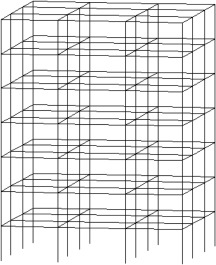
First, a 7-story structure with 3 spans in each horizontal direction is considered. The frames in both directions are moment resisting and all joints are fixed. The 3D view of this structure is presented in Figure 2 . The flooring system is considered to be a two-way slab. Thus, the coefficients of loading in two-way slabs are used to distribute the dead and live loads to the beam members. In this paper, slabs are set to be non-rigid and all the joints have 6 degrees of freedom. Lateral forces affecting the structure are entered to the center of the mass of each story, and, due to the symmetry, the center of stiffness coincides with the center of the mass. Thus, torsional effects in the plan can be neglected. Lateral force in each story is divided equally among 4 centric joints.
|
|
|
Figure 2. 3D view of a 7-story structure. |
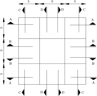
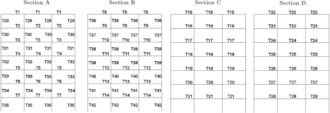
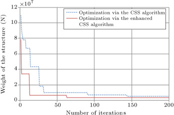
The algorithm, by default, selects individual values for each member, and, at last, we will have a structure with each member’s section being different. Therefore, we should have some type classifications to group the beams and columns of the frames. The sections and planar dimensions are illustrated in Figure 3 . In Figure 4 , the frame sections and type classifications are presented. In this way, we have 42 groups of members, which are shown by T1–T42 in Figure 4 . The results of the optimal design of this structure via CSS and enhanced CSS algorithms are presented in Table 3 . In this table, the sections that are finally chosen by each algorithm, according to Table 1 and Table 2 , are displayed. Also, the weight of each member and sum of the weights for each design are presented in Table 3 , in order to report the optimum weights. The design histories for both CSS and enhanced CSS algorithms are shown in Figure 5 . As obvious from this figure, the downfall of the CSS curve in the initial steps demonstrates the power of the method in exploration. This behavior continues in the first 10 iterations, completing the global search phase. Then, the local search starts and in 50 steps, the minimum solution is found, completing the exploitation phase of the algorithm. The number of maximum iterations in this paper is chosen to be 200, to assure the results for stochastic decline. Also, it is clear that the enhanced version of the CSS algorithm has a better minimum solution obtained in fewer steps.
|
|
|
Figure 3. Planar dimensions and sections. |
|
|
|
Figure 4. Type classification of beams and columns previewed in 4 sections presented in Figure 3 . |
| Type classification of members | Optimal design by CSS | Weight of cross sections ( ) | Optimal design by ECSS | Weight of cross sections ( ) |
|---|---|---|---|---|
| T1 | B3-type 4 | 0.179 | B3-type 2 | 0.177 |
| T2 | B3-type 3 | 0.177 | B3-type 3 | 0.177 |
| T3 | B3-type 3 | 0.177 | B7-type 1 | 0.413 |
| T4 | B3-type 3 | 0.177 | B7-type 2 | 0.414 |
| T5 | B5-type 2 | 0.177 | B7-type 3 | 0.415 |
| T6 | B7-type 5 | 0.422 | B8-type 2 | 0.521 |
| T7 | B11-type 4 | 0.772 | B8-type 4 | 0.530 |
| T8 | B9-type 1 | 0.568 | B9-type 4 | 0.580 |
| T9 | B9-type 2 | 0.570 | B10-type 1 | 0.616 |
| T10 | B9-type 4 | 0.580 | B10-type 1 | 0.616 |
| T11 | B10-type 1 | 0.616 | B10-type 5 | 0.632 |
| T12 | B11-type 4 | 0.772 | B10-type 5 | 0.632 |
| T13 | B12-type 2 | 0.806 | B10-type 5 | 0.632 |
| T14 | B12-type 3 | 0.808 | B12-type 5 | 0.827 |
| T15 | B3-type 4 | 0.179 | B3-type 2 | 0.177 |
| T16 | B3-type 3 | 0.177 | B3-type 3 | 0.177 |
| T17 | B3-type 3 | 0.177 | B7-type 1 | 0.413 |
| T18 | B3-type 3 | 0.177 | B7-type 2 | 0.414 |
| T19 | B5-type 2 | 0.331 | B7-type 3 | 0.415 |
| T20 | B7-type 5 | 0.422 | B8-type 2 | 0.521 |
| T21 | B11-type 4 | 0.772 | B8-type 4 | 0.530 |
| Sum of the weights | 9.832 | 9.039 | ||
| T22 | B9-type 4 | 0.580 | B9-type 1 | 0.568 |
| T23 | B10-type 1 | 0.616 | B9-type 2 | 0.570 |
| T24 | B10-type 1 | 0.616 | B9-type 4 | 0.580 |
| T25 | B10-type 5 | 0.632 | B10-type 1 | 0.616 |
| T26 | B10-type 5 | 0.632 | B11-type 4 | 0.772 |
| T27 | B10-type 5 | 0.632 | B12-type 2 | 0.806 |
| T28 | B12-type 5 | 0.827 | B12-type 3 | 0.808 |
| T29 | C1-type 5 | 0.099 | C2-type 1 | 0.153 |
| T30 | C2-type 1 | 0.153 | C2-type 1 | 0.153 |
| T31 | C2-type 1 | 0.153 | C2-type 1 | 0.153 |
| T32 | C2-type 1 | 0.153 | C2-type 1 | 0.153 |
| T33 | C2-type 1 | 0.153 | C2-type 1 | 0.153 |
| T34 | C5-type 1 | 0.389 | C2-type 4 | 0.159 |
| T35 | C5-type 3 | 0.396 | C4-type 2 | 0.302 |
| T36 | C6-type 5 | 0.525 | C6-type 3 | 0.514 |
| T37 | C6-type 5 | 0.525 | C6-type 3 | 0.514 |
| T38 | C7-type 1 | 0.619 | C6-type 3 | 0.514 |
| T39 | C7-type 1 | 0.619 | C6-type 3 | 0.514 |
| T40 | C7-type 1 | 0.619 | C6-type 3 | 0.514 |
| T41 | C7-type 4 | 0.635 | C11-type 1 | 1.193 |
| T42 | C9-type 2 | 0.874 | C11-type 1 | 1.193 |
| Sum of the weights | 10.901 | 10.446 | ||
|
|
|
Figure 5. Design optimization of 7-story RC 3D structures via CSS and enhanced CSS algorithms. |
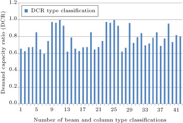
Figure 6 shows the maximum values of the demand capacity ratio (DCR), i.e., the maximum of for beam–columns in all groups, under cases of critical loading. For each group, if this ratio is near to 1.0, it shows that the section is optimum for that group. From this figure, it can be observed that the Maximum DCR for some groups is close to 1.0 and some of them are between 0.6 and 0.8. This is because of other constraints, such as slenderness of column; story drift and natural period of the structure. It can also be because of the limitation of sections used in the process of optimum design.
|
|
|
Figure 6. Maximum DCR of members for each type classification. |
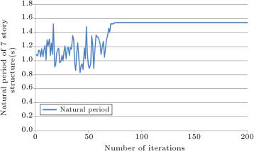
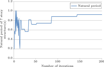
The history of the natural period of the structure is presented in Figure 7 . This figure demonstrates that in the initial stages of iteration, the value of the natural period has a large range of variation, but, after 60 iterations, this value improves and, at 80 iterations, it converges and takes a constant value. Increasing the period during the design history is the result of reduction in section sizes and the more flexible behavior of the structure.
|
|
|
Figure 7. History of natural period of 7-story structure. |
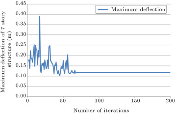
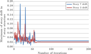
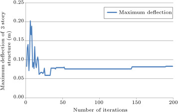
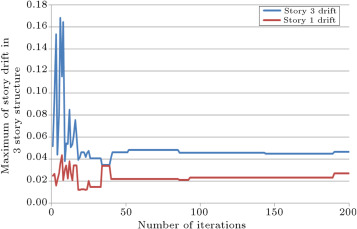
In Figure 8 and Figure 9 , the history of the maximum deflection of the structure and the story drifts of the structure are presented, respectively. Variation of the values for deflections and drifts for 60 initial iterations are because of algorithm exploration. After this number of iterations, exploitation of the algorithm causes the convergence of these values to a constant value. Drift constraints based on the ACI 318-05 code are used in the program to control the deflection of the structure.
|
|
|
Figure 8. History of maximum deflection of the structure. |
|
|
|
Figure 9. History of drift of structure in stories 3 and 7. |
8. Sensitivity analysis
In this section, 9 three story structures with 3 spans in each horizontal direction are considered. The sensitivity analysis is performed by changing span size and loading conditions, and results are compared. The span sizes are 6, 7 and 9 m and loading coefficients for the above mentioned loadings are 1, 1.25 and 1.5. The algorithm used for these designs is the enhanced CSS. Because of constructional conditions, we should consider some type of classification in the selection of sections for the beams and columns of each frame. For example, in opposite frames in each story, beam and column members are defined to be similar. Also, the 2 innermost frame beam members are similar to each other. Figure 10 presents the 3D view of these structures, in addition to the type classification of the members. Thus, we have 15 groups of members and the algorithm will choose sections for these groups.
|
|
|
Figure 10. 3D view of 3-story structure and type classification of beams and columns. |
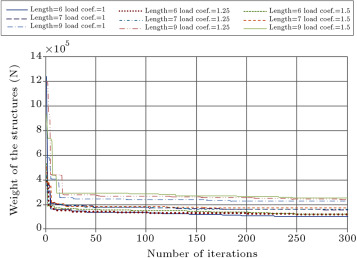
The result of sensitivity analysis of the optimal design of these structures via the enhanced CSS algorithm is presented in Table 4 . In this table, the sections that are finally chosen by the algorithm, according to Table 1 and Table 2 , are displayed. The optimum design histories for the sensitivity analysis via the enhanced CSS algorithm are shown in Figure 11 . The gradual increase of the section sizes of the members and the weight of the structures by an increment of the length and loading coefficient of each structure is obvious from Table 4 . Also, the increment of optimum weight in the design history of each structure by the growth of the length and loading coefficients is noticeable from Figure 11 .
| Type classification of members | Length = 6 | Length = 6 | Length = 6 | Length = 7 | Length = 7 | Length = 7 | Length = 9 | Length = 9 | Length = 9 |
|---|---|---|---|---|---|---|---|---|---|
| loading coefficient = 1 | loading coefficient = 1.25 | loading coefficient = 1.5 | loading coefficient = 1 | loading coefficient = 1.25 | loading coefficient = 1.5 | loading coefficient = 1 | loading coefficient = 1.25 | loading coefficient = 1.5 | |
| T1 | B3-type 5 | B3-type 5 | B4-type 2 | B3-type 3 | B3-type 5 | B3-type 3 | B3-type 5 | B4-type 5 | B3-type 5 |
| Weight ( ) | 0.179 | 0.179 | 0.249 | 0.177 | 0.179 | 0.177 | 0.179 | 0.254 | 0.179 |
| T2 | B3-type 3 | B3-type 3 | B4-type 2 | B3-type 5 | B4-type 3 | B3-type 5 | B3-type 5 | B4-type 5 | B3-type 5 |
| Weight ( ) | 0.177 | 0.177 | 0.249 | 0.179 | 0.250 | 0.179 | 0.179 | 0.254 | 0.179 |
| T3 | B4-type 1 | B4-type 1 | B4-type 2 | B3-type 5 | B4-type 3 | B3-type 5 | B3-type 5 | B7-type 3 | B3-type 5 |
| Weight ( ) | 0.248 | 0.248 | 0.249 | 0.179 | 0.250 | 0.179 | 0.179 | 0.415 | 0.179 |
| T4 | B5-type 2 | B5-type 1 | B6-type 3 | B8-type 3 | B7-type 4 | B8-type 3 | B8-type 2 | B11-type 3 | B11-type 3 |
| Weight ( ) | 0.331 | 0.330 | 0.374 | 0.523 | 0.421 | 0.523 | 0.521 | 0.756 | 0.756 |
| T5 | B6-type 3 | B5-type 4 | B6-type 5 | B5-type 4 | B7-type 4 | B8-type 3 | B8-type 5 | B12-type 3 | B11-type 4 |
| Weight ( ) | 0.374 | 0.336 | 0.380 | 0.336 | 0.421 | 0.523 | 0.532 | 0.808 | 0.772 |
| T6 | B6-type 5 | B6-type 1 | B8-type 4 | B6-type 1 | B7-type 4 | B8-type 5 | B9-type 3 | B12-type 5 | B11-type 4 |
| Weight ( ) | 0.380 | 0.372 | 0.530 | 0.372 | 0.421 | 0.532 | 0.571 | 0.827 | 0.772 |
| T7 | B3-type 5 | B3-type 5 | B4-type 2 | B3-type 3 | B3-type 5 | B3-type 3 | B3-type 5 | B4-type 5 | B3-type 5 |
| Weight ( ) | 0.179 | 0.179 | 0.249 | 0.177 | 0.179 | 0.177 | 0.179 | 0.254 | 0.179 |
| T8 | B3-type 3 | B3-type 3 | B4-type 2 | B3-type 5 | B4-type 3 | B3-type 5 | B3-type 5 | B4-type 5 | B3-type 5 |
| Weight ( ) | 0.177 | 0.177 | 0.249 | 0.179 | 0.250 | 0.179 | 0.179 | 0.254 | 0.179 |
| T9 | B4-type 1 | B4-type 1 | B4-type 2 | B3-type 5 | B4-type 3 | B3-type 5 | B3-type 5 | B7-type 3 | B3-type 5 |
| Weight ( ) | 0.248 | 0.248 | 0.249 | 0.179 | 0.250 | 0.179 | 0.179 | 0.415 | 0.179 |
| T10 | C2-type 4 | C2-type 5 | C3-type 4 | C3-type 3 | C3-type 5 | C4-type 2 | C4-type 5 | C5-type 5 | C7-type 4 |
| Weight ( ) | 0.159 | 0.161 | 0.225 | 0.223 | 0.227 | 0.302 | 0.309 | 0.403 | 0.635 |
| T11 | C2-type 4 | C2-type 5 | C3-type 5 | C3-type 4 | C3-type 5 | C4-type 3 | C4-type 5 | C5-type 5 | C7-type 4 |
| Weight ( ) | 0.159 | 0.161 | 0.227 | 0.225 | 0.227 | 0.305 | 0.309 | 0.403 | 0.635 |
| T12 | C3-type 3 | C2-type 5 | C4-type 3 | C4-type 5 | C3-type 5 | C5-type 4 | C4-type 5 | C10-type 2 | C9-type 1 |
| Weight ( ) | 0.223 | 0.161 | 0.305 | 0.309 | 0.227 | 0.399 | 0.309 | 1.044 | 0.869 |
| T13 | C3-type 5 | C5-type 2 | C4-type 2 | C6-type 3 | C5-type 3 | C9-type 2 | C5-type 4 | C6-type 5 | C5-type 4 |
| Weight ( ) | 0.227 | 0.393 | 0.302 | 0.514 | 0.396 | 0.874 | 0.399 | 0.525 | 0.399 |
| T14 | C4-type 1 | C8-type 5 | C7-type 5 | C9-type 5 | C9-type 3 | C10-type 3 | C8-type 3 | C7-type 3 | C7-type 5 |
| Weight ( ) | 0.298 | 0.752 | 0.640 | 0.891 | 0.880 | 1.052 | 0.741 | 0.630 | 0.640 |
| T15 | C6-type 4 | C8-type 5 | C7-type 5 | C10-type 2 | C9-type 5 | C10-type 3 | C9-type 3 | C8-type 1 | C8-type 1 |
| Weight ( ) | 0.519 | 0.752 | 0.640 | 1.044 | 0.891 | 1.052 | 0.880 | 0.730 | 0.730 |
| Sum of weights ( ) | 3.878 | 4.625 | 5.116 | 5.508 | 5.968 | 6.635 | 6.648 | 7.971 | 8.286 |
|
|
|
Figure 11. Sensitivity analysis of the optimum design of RC 3D structures by changing span size and loading coefficient. |
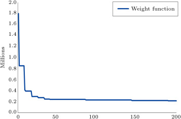
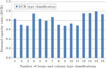
In Figure 12 , Figure 13 , Figure 14 , Figure 15 and Figure 16 , the parameters studied for the 7-story structure are presented for a 3-story structure with a 9 m span length and a load coefficient of 1.5 once more, to monitor the constraint values during the design process. The following points can be observed:
|
|
|
Figure 12. Design history of 3-story structure with 9 m span size and load coefficient of 1.5. |
|
|
|
Figure 13. Maximum DCR of members for each type classification for 3-story structure. |
|
|
|
Figure 14. History of natural period of 3-story structure. |
|
|
|
Figure 15. History of maximum deflection of 3-story structure. |
|
|
|
Figure 16. History of drift of structure in stories 3 and 1. |
Footfalls that exist in the design history of this structure are transmitted to the other figures, as presented in Figure 12 , Figure 13 , Figure 14 , Figure 15 and Figure 16 . This means that an exploitation of the algorithm has occurred, even in the final iterations, leading to better results for optimal design of the structure.
9. Concluding remarks
Optimization of large structures requires a considerable amount of computational time, because each analysis and design step needs a great deal of time to run. It is obvious that some optimization algorithms that need considerable iterations to achieve a good result cannot be used to optimize the design of large structures. The CSS and the enhanced CSS methods are in the group of algorithms that optimizes the structures in a small number of iterations. A more thorough comparison between the CSS and its enhanced version and other meta-heuristic algorithms is performed for the design optimization of skeletal structures in [11] , illustrating the superiority of the CSS algorithm, as shown in Figure 17 . In order to avoid a similar comparison, in this paper, only a comparison between the CSS and enhanced CSS is performed.
|
|
|
Figure 17. Comparison of convergence history for unbraced space frame [11] . |
Obviously, the design optimization of the 3D structures will be useful for future industrial buildings. Meta-heuristic algorithms, such as the ones utilized in this paper, which simplify the process of the optimization process, will be suitable tools. Equivalent linear analysis, predetermined sections and disregard for outside walls are some simplifying assumptions used in this paper. Future research work should also include such effects.
Acknowledgment
The first author is grateful to the Iran National Science Foundation for its support.
References
- [1] M.M. Fadaee, D.E. Grierson; Design optimization of 3D reinforced concrete structures; Structural Optimization, 12 (1996), pp. 127–134
- [2] R.J. Balling, X. Yao; Optimization of reinforced concrete frames; Journal of Structural Engineering, ASCE, 123 (1997), pp. 193–202
- [3] S. Rajeev, C.S. Krishnamoorthy; Genetic algorithm-based methodology for design optimization of reinforced concrete frames; Computer-Aided Civil and Infrastructure Engineering, 13 (1998), pp. 63–74
- [4] A. Kaveh, S. Talatahari; A novel heuristic optimization method: charged system search; Acta Mechanica, 213 (3–4) (2010), pp. 267–286
- [5] A. Kaveh, S. Talatahari; An enhanced charged system search for configuration optimization using the concept of fields of forces; Structural and Multidisciplinary Optimization, 43 (2010), pp. 339–351
- [6] Minimum Design Loads for Buildings and Other Structures, ASCE7-05; American Society of Civil Engineers (ASCE) (2005)
- [7] Building Code Requirements for Structural Concrete and Commentary, ACI 318-05; American Concrete Institute (ACI) (2005)
- [8] A. Kaveh, S. Talatahari; A charged system search with a fly to boundary method for discrete optimum design of truss structures; Asian Journal of Civil Engineering, 11 (3) (2010), pp. 277–293
- [9] Z.W. Geem, J.H. Kim, G.V. Loganathan; A new heuristic optimization algorithm: harmony search; Simulation, 76 (2001), pp. 60–68
- [10] A. Kaveh, O. Sabzi; A comparative study of two meta-heuristic algorithms for optimal design of planar RC frames; International Journal of Civil Engineering IUST, 9 (3) (2011), pp. 193–206
- [11] A. Kaveh, S. Talatahari; Optimal design of skeletal structures via the charged system search algorithm; Structural Multidisciplinary Optimization, 41 (2010), pp. 893–911
Document information
Published on 06/10/16
Licence: Other
Share this document
Keywords
claim authorship
Are you one of the authors of this document?

![Comparison of convergence history for unbraced space frame [11].](/wd/images/5/5b/Draft_Content_514306669-1-s2.0-S1026309813000588-gr17.jpg)