Abstract
Optimization of the use of resources and adaptability of the structures to their environment are new concerns in architecture and structural engineering. At the same time, ephemeral structures are gaining relevance in the market for their uses in maintenance and repair, organization of events, rescue and emergencies and temporary works.
Inflatable structures satisfy two of the points aforementioned: they require small amounts of materials and are adequate for ephemeral structures, due to their low deflated volume and lightness. They are also adaptable in the sense that their overpressure determines their load carrying capacity. However, they are inadequate for environments where high external loads may be present.
Tensairity appears as a solution to this problem, increasing the carrying capacity of inflatable structures without renouncing to their advantages. This technology adds two extra structural elements to inflatable beams, with greater strengths, in order to redistribute stresses along it. The inflatable element serves then to couple the two stiff elements and to avoid buckling.
This work presents and explores design possibilities of Tensairity beams with special focus on their computational modelling. Then, research is carried out regarding modular Tensairity beams, thought as a solution for deployable footbridges. A prototype was built and tested in serviceability conditions to prove the fitness of the proposal to a commercial level.
Resumen
La optimización de los recursos y la adaptabilidad de las estructuras a su ambiente son nuevas tendencias en la arquitectura y la ingeniería estructural. Al mismo tiempo, las estructuras efímeras están ganando relevancia en el mercado por sus usos en tareas de mantenimiento y reparación, organización de eventos, operaciones de salvamento y emergencia y obras temporales.
Las estructuras hinchables satisfacen dos de los puntos arriba mencionados: usan poco material y son adecuadas para usos efímeros debido a su bajo volumen al desinflarse y su ligereza. También son adaptables en cuanto que su presión determina su capacidad de carga máxima. Sin embargo, son poco aptas para ambientes donde se esperan cargas externas elevadas.
Tensairity aparece como una solución a este problema, incrementando la resistencia de carga máxima de las estructuras inflables sin renunciar a sus otras ventajas. Esta tecnología añade dos elementos estructurales a la viga hinchable, con mayor resistencia frente a esfuerzos, para redistribuir la carga. El elemento inflable sirve entonces para acoplar los elementos rígidos y para evitar el pandeo.
Este trabajo presenta y explora posibilidades de diseño de vigas Tensairity con atención especial a su modelado computacional. Después, se investiga sobre vigas Tensairity modulares como solución de pasarelas portátiles. Se ha construido un prototipo para probarlo bajo condiciones de servicio y valorar así su validez a nivel comercial.
Dedication
To my family, for letting me come to Barcelona and have this opportunity, and my friends here, for making me want to stay. Especially, I want to dedicate this to Javi and Dani, who have been with me from minute one up to now. You are what made this city great for me in the first place.
Declaration
I, Alberto Rodríguez Jiménez, declare that all the work presented in this document is my own or, when other author`s content has been used, it has been properly referenced in the bibliography of this document.
Acknowledgments
First, I would like to thank my supervisor, Professor Eugenio Oñate, for the opportunity and support in the development of this work. Special thanks also to Mr. Javier Marcipar for the continuous brainstorming and interest in this project; and to Dr. Omar Salomón, for his guidance, availability and his patience for solving my many doubts and questions.
I am also very thankful to Dr. Carles Estruch and the rest of the crew in BuildAir for their help in building the prototype and their disposition to stop their work to help in this project. In the same way, I appreciate the help from Mr. Miguel Ángel Sánchez and Professor Rolando Chacón in the making and testing of the prototype, and I thank Mr. Tomás García for the use of some of his equipment and tools.
Introduction
Traditional building methods account for the largest share of primary energy consumption worldwide [1]. This is due to several reasons; mainly, the high emission levels in the production of concrete and steel and the conservative design of the structures, which consider large load cases that may never happen during the service life of the structure. As a result, permanent structures tend to be large and, although having the advantage of being on the safe side, have an ‘excess’ of material. This fact causes economical inefficiency during construction but also during management and maintenance, as more material can be damaged and some parts of the structure may be harder to reach and repair.
Inflatable structures were thought as an alternative to traditional ones to solve these issues. Air pressure lets us reduce the necessary amount of building material, similarly to the effect of pretensioning in concrete structures. In addition, changing the air pressure makes the structure adaptable to live loads, limiting the energy consumption of the inflation during the most common load scenarios, in which a high resistance is unnecessary.
On the other hand, inflatable structures present several disadvantages. The materials used for inflation are flexible and less resistant than traditional ones. Therefore, load carrying capacity of these structures is low for many applications in Civil Engineering, or too large air pressures would be needed to perform correctly. Due to the inevitable pressure loss through membranes, a high energy cost should be assumed to keep the structure inflated, which contradicts the principle of energy saving they pursue. In addition, membranes are weak against sting and piercing loads and, at the same time, are prone to wrinkling under excessive flexural and axial loads. Durability is then a critical issue when designing an inflatable structure.
Due to these limitations, inflatable structures have been traditionally used for the construction of temporal pavilions and other uses which require little bearing capacity: goal arcs, advertisement panels and structures or tents, where the only purpose of the structure is the isolation from the exterior.
This work focuses on the development of an inflatable bridge that overcomes the main disadvantages aforementioned; namely, the need for high air pressure and the low load carrying capacity while maintaining its lightness and versatility. The first chapter overviews the market and history of light and inflatable structures. The second one introduces Tensairity, the new technology used for the design of the bridge. The third chapter applies the gained theoretical knowledge in benchmark problems and introduces the computational modelling of such structures. The design process of the bridge is presented in the fourth chapter and, finally, the fifth one gives the economic and feasibility analysis of the bridge.
1. State of the art
The first human-built structures were simple tents made of animal skin strips supported by sticks. These satisfied the need for quick deployment and dismantle and were very light, in accordance to the nomadic style of life of those times. The main function of these structures was simply to isolate the interior from the weather conditions outside, mainly cold, rain and winds. Hide and leather worked as membrane elements that distributed the load to the sticks and then to the soil.
Once people started claiming lands, buildings started being demanded other capabilities, such as comfort, larger inner space and durability. Consequently, builders changed materials, moving to mortar, adobe and wattle and daub, creating walls and surfaces that acted as slabs and shells. Of course, stones were used as well, but mainly to build tombs and monuments.
During these ancient times, structural schemes still preferred tension and compression to bending, as it uses more efficiently the whole section of the structural element. The evolution of structures corresponded to a trade-off between durability and load bearing capacity and lightness, but the structural concepts were similar. However, the development of new techniques and materials changed architecture, especially during the classical age. The appearance of the roman bricks and concrete allowed the construction of larger and more diverse structures, at the cost of increasing the weight and loads in the structure. Large spans now required columns, and arches were used to distribute loads from walls to the foundations [2]. The new materials allowed for a rapid diversification and growth of the settlements, at the cost of removing tension off the structural schemes. Building elements started working in compression and bending, most like modern concrete does.
Vitruvius’s laws of architecture, Firmitas, Utilitas and Venustas [3], summarise the functions required to classical buildings, that is, solidity, utility -understood as serviceability and commodity- and aesthetics. These principles have remained untouched from Roman times up to our days. The first principle is often seen as robustness in, for example, architectural currents such as brutalism.
Because of this view of architecture, traditional construction breaks the surrounding environment, clearly distinguishing urban and rural landscapes. What is more, traditional buildings use large amounts of aggregates and sands, as well as steel, which are obtained by modifying the natural landscape. As opposed to this drawback, and according to the principles of sustainability, a new architecture has arisen that minimises the impact of urban concentration in the landscape and the environment. Some first examples of this new current are found in the eco-districts of Vauban, Germany, and Ekoviikki, Finland. These new neighbourhoods focus on the integration of the urban landscape within the natural, green one and on energy sustainability.
On the other hand, other technicians have focused on material savings and the inclusion of curves and natural forms in buildings. Light structures achieve that by returning to the schemes of the first built structures: the tents. They use membranes that, correctly pretensioned, adapt and maintain curvature. The lightness of these structural elements makes them suitable for adaptive uses, like the retractable rooftops of some football stadiums.
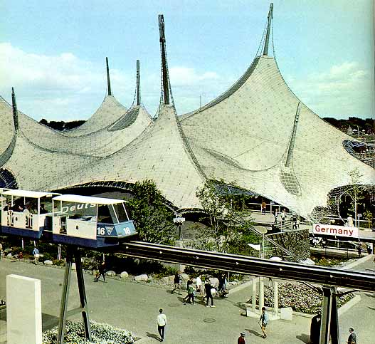
However, membranes still lack the strength to bear important loads by themselves, so they are often used as part of larger and heavier structures or in temporary installations. A well-known example of the latter is the West Germany Pavilion at Expo 67, shown in Figure 1.
|
| Figure 1: West Germany Pavilion at Expo 67 |
Inflatable and air-supported structures appeared as an improvement of tensile ones. These new systems use air pressure to stiffen the membrane layers, so that it is possible to get rid of other heavy structural elements. Inflatable systems have pressurised air between two layers of membrane, while air-supported ones pressurise the whole space occupied by the building. Consequently, the last ones need airlocks in the access points to prevent pressure losses.
Inflatable structures have the advantage of being self-supporting when inflated; they usually need only some connector to transmit forces to the ground. In addition, they can adapt to different external conditions by regulating the internal pressure. Generally, the more pressure, the more resistant the structure, even though maintaining high pressures is costly and therefore avoided whenever possible. This increase in costs limits the load bearing capacity of these structures, which are still weaker than traditional ones, although their live/dead load ratio is higher: usually lower than 3 in traditional structures and more than an order of magnitude higher for reinforced inflatable ones [4].
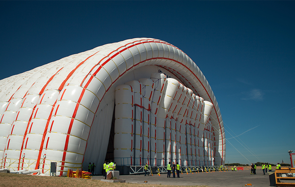
All in all, inflatable structures reduce the necessary heavy elements in a structure, reducing its bearing capacity but allowing them to support themselves. As a result, inflatable schemes are often used for temporal structures, like the tensile ones. The most common uses include expo pavilions, goal arcs and advertisement totems and tents. Their best property, apart from their lightness, is the ability to create isolated clear spans. This started being used recently to build hangars for aeronautical and industrial applications by companies like Buildair. Figure 2 shows the largest inflatable structure built so far, a hangar for maintenance of planes in the military base of Getafe, Spain.
|
| Figure 2: Inflatable hangar for maintenance of planes |
There are many companies specialised in the design and manufacturing of inflatable structures. This is an already consolidated market, being its most profitable part the design of portable event structures. Apart from this, there is another market in providing for the military and civil protection agencies. The principal applications of inflatable structures there are quick deployment and disassembly of camps and buildings for emergencies such as medical assistance and chemical/biological protection. Another use of these structures is the prevention of floods with portable dams, which adapt their internal pressure to changing water levels. These structures are used to control low-level flows, such as irrigation channels and they present many advantages over the classical regulation methods: larger spans, adaptability and the capability of being laid on the river bottom without obstructing the river [5]. This project derives from a similar idea: an inflatable structure that helps during flood events. In this case, its function is the safe transport of people above waterlogged surfaces. The concept is then that of an inflatable bridge for emergency use. Then, it should be light, portable and thin, allowing the pass of one person or wheelchair at a time. The versatility of this design makes it useful also in other scenarios that require an emergency footbridge.
1.1 Other temporary and deployable bridges
This product would compete against any other emergency footbridge. For that reason, it is adequate to study the current situation of inflatable structures for transportation, focusing then on the market of emergency and deployable bridges, especially for pedestrian use. The idea of using inflatable structures for transportation is not new. Most of their applications so far are ephemeral structures of quick deployment, being perhaps the evacuation ramp in commercial airplanes the most common example. There are also vehicles that use this technology, such as zeppelins and modules of aerospace vehicles and many inflatable boats like the Zodiac. Inflatable structures for in-land transportation have rarely been used. One example is the Lightweight Modular Causeway System, used and designed by the United States army. This consists of a series of inflatable cylinders supported on the river bed which bears a stiff deck. The result is a light bridge, weighting 900 kg per linear meter that can carry heavy military vehicles. It needs a boat to be deployed. Inflatable beams as bridges exist since at least 1942. Their conception was always as quick-deployment structures for the army until a new model [6], developed in 1993, was created for rescue operations. It consists of inflatable hoses that support a walkway and have inner and outer reinforcement layers for increased axial and transversal stiffness. The inner layer is comprised of parallel longitudinal threads, while the outer one consists of two helicoids running in opposite directions. This is a similar concept as the one used in Tensairity, which will be explained in the following chapter.
|
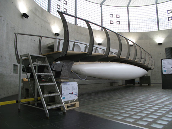
| Figure 3: Inflatable footbridge prototype by Tensairity Solutions |
Although the concept is not new, nowadays it is hard to find inflatable footbridges in the market. Puntec Industries claims to produce customised inflatable footbridges and bridges on its website, and the ETH University in Zürich, in collaboration with the Swiss Federal Laboratory for Materials Science and Technology and Tensairity Solutions 1, have designed and tested the footbridge of Figure 3, but it is not a commercial model so far. This same company produces heavier models, with larger spans and load carrying capacity to allow the passing of vehicles. These models, however, are not in direct competition with the model proposed in this thesis. Therefore, if the product designed here were released to the market, it would not compete against other similar inflatable bridges. Nonetheless, there are other solutions with classical materials that could compete with this one:
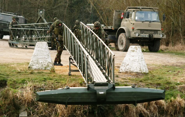
- Infantry Assault Bridge (IAB) by General Dynamics. IAB is a light modular bridge in aluminium, with clear spans of up to 30 meters. It has a very thin cross-section with a railing system to ease the crossing. It can be deployed very quickly after assembly by means of a floating support (Figure 4) if it is used to cross a water mass and is especially designed for being used in armies. European Land Systems, part of General Dynamics, produces this bridge. This company produces vehicles and structures for armies and its headquarters are in Madrid, Spain. It has more than 1800 employees in Austria, Czech Republic, Germany and Switzerland.
- Mabey Pedesta. Footbridge made of fibre-reinforced plastic (FRP), in this case with glass fibre. It is thought as a permanent solution for zones with difficult access, and so the design can be personalised to suit the environment and climatic conditions. Its design is modular and 70% lighter than it would be if steel was used. Each module is 1 meter long, with a maximum span of 30 meters thanks to posttensioning. It requires a crane for its construction and its capital cost is similar to that of a traditional steel bridge. However, the reduction of maintenance allows for savings during its 120 years of service life. Mabey is an international company founded almost 100 years ago with more than 800 employees nowadays. It operates in 142 countries worldwide and made more than 110 million pounds in income in 2015. This company offers other model of a bridge for pedestrians, based on 3 meter long steel modules, which can be assembled with light equipment.
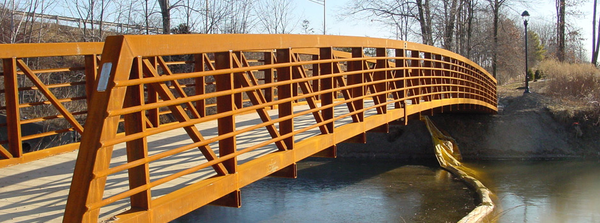
- Pedestrian footbridge by Acrow. Prefabricated modular steel bridge as the one seen in Figure 5. Thought for temporary and permanent uses, especially in construction, excavation and drilling sites. Acrow is an American company specialised in modular steel bridges, with more than 50 years of experience. It operates mainly in the USA and Canada, with offices also in South Africa.
|
| Figure 4: IAB with floating module during deployment |
|
| Figure 5: Pedestrian bridge by Acrow |
When considering the market of deployable bridges, not focusing only on those for pedestrian use, there are many other available models. A review of these is shown in the following, briefly describing the bridge itself and the companies that offer it.
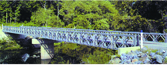
- Bailey bridge [7]. The most common portable system of deployable bridges. It consists of prefabricated modules that can be put together in site without the need of heavy equipment, using only common tools. The parts are made of steel, strong enough to carry heavy vehicles according to the scheme of the bridge. An example is shown in Figure 6. This type of bridge can be used to cover spans ranging from 10 to 61 meters. Larger spans can be reached if intermediate piers are placed. Assembly time depends on the needed span but generally it takes a few days. As this system is the most used for deployable bridges, it is commercialised by several companies being some of them Bailey Bridges Inc., Acrow and Mabey.
- Amphibious bridges. Some heavy vehicles, such as the Engin de Franchissement de l'Avant (EFA), in the French army, or the M3 vehicle of the British army, can be driven underwater and aligned to form a bridge. These are able to carry other heavy vehicles, such as tanks or trucks. The M3 vehicle is produced by General Dynamics European Land Systems.
|
| Figure 6: Single storey Bailey bridge by Bailey Bridges Inc. |
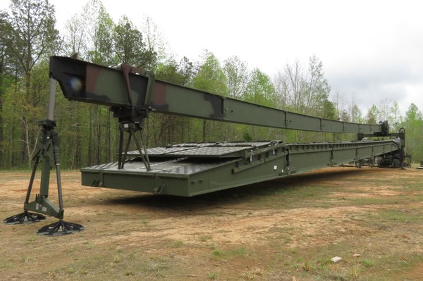
- Dry support bridge (DSB). This bridge is deployed from a special vehicle (Figure 7) in less than 90 minutes and spans a maximum of 46 meters. It allows the passage of heavy vehicles and requires only eight people for the deployment operations. DSB is produced by WFEL, a company focused on tactical military bridging. It was funded forty years ago and is based in the United Kingdom, from where it serves 39 armed forces around the world. This company produces another bridge model, the Medium Girder Bridge (MGB), that needs cranes or other heavy equipment to be deployed. Depending on its scheme, the MGB can span up to 50 meters or 76 meters in a multi-span bridge, being able to carry heavy vehicles.
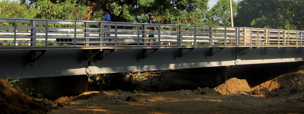
- Unibridge. Prefabricated modular metallic bridge with spans up to 45 meters. There are different kinds of modules, even one for cyclists and pedestrians, like the one in Figure 8. It requires heavy equipment for the deployment. This bridge is produced by Matière, a French company with offices all around the world, although it produces bridges only in France. Its turnover was 115 M€ in 2014 and it has 415 employees.
- Panel bridge. Light steel modular bridge, which deck is formed by standard panels, similar to the single storey Bailey bridge. Panels are welded to each other, which makes the deployment slower. Besides, this bridge is thought for permanent use, not temporary nor for emergencies.Panel bridges are produced by Waagner Biro, an Austria-based company with more than 1300 employees nowadays and offices in Europe, the Middle East and Southeast Asia. Waagner Biro is not focused entirely in the design and construction of bridges; it also builds steel-glass structures and provides stage and special machinery equipment. Apart from panel bridges, they also produce modular bridges, tailor-made structures that adapt better to the specific environment but require larger periods for construction.
Research is being carried out with new materials, especially fibre-reinforced plastics like the one already in use by Mabey in its Pedesta bridge. As mentioned in [8], there have been several studies on the behaviour of FRP in the design of short-span emergency bridges. Although there are no commercial applications of these new materials so far in temporary applications (the Pedesta bridge is thought as a permanent solution), it is very likely that commercial models will be released into market in the near future, although the ones tried so far are still too heavy to be practical. A solution to reduce weight and ease packaging has been patented [9], which consists in using a high pressure membrane as compression element. This new membrane surrounds the airbeam and is tightly connected to it by a sheath. This structure is lighter than any using classical materials and can be folded into small volumes when deflated for transportation.
|
| Figure 7: Dry Support Bridge |
|
| Figure 8: Pedestrian Unibridge |
(1) http://www.tensairitysolutions.com/applications/pedestrian-footbridge-tensairity/
2. Tensairity
As already mentioned before, the goal of this work is to design a prototype of inflatable bridge for emergencies. This structure needs to be light, portable and easily deployable while maintaining enough load carrying capacity. Classical inflatable structures rarely present enough strength to bear the external loads or, in order to do so, they would need high internal pressure. A way of solving this problem is reinforcing an inflatable beam with materials stronger that the inflatable membrane to bear the loads. Tensairity does exactly that, separating compression and tension into two new elements of the beam.
Tensairity is a technology developed by R.H. Luchsinger and his work team at the ETH in Zürich and patented by M. Pedretti and R. Luscher [10]. Buildair has a commercial agreement to use this technology in temporal bridge applications. It is based on Tensegrity, which in turn is a structural scheme composed of wires and bars. These wires and bars are connected to create frames with particular geometries so that wires are only tensioned and bars are only compressed. This distribution of forces gives many advantages to these structures compared to traditional ones: they are light and efficient as the whole sections of the bars are equally solicited, they are deployable as the wires can be folded and their reliability can be more easily modelled since only axial internal forces appear[11].
Tensegrity structures copy the scheme of spider webs. In the same way, also Tensairity is inspired in structures of the nature. In this case, Tensairity copies the combination of compressive and tensile forces that surround the fluid in plant stems [12]. In Tensairity beams, this fluid is simply compressed air, which adds several benefits to the Tensegrity technology. The principal advantage of Tensairity over Tensegrity is that buckling of the compression members can be avoided for any external load by adjusting the internal pressure [13]. Some other advantages are that the load bearing capacity of the structural element can be increased to up to two orders of magnitude with respect to pneumatic structures [14] and, if designed correctly, they are self-supporting even with zero internal pressure.
Tensairity is a relatively new technology. Bibliography about this topic started to appear in 2004 but during these years the design of Tensairity beams and girders has changed considerably. In the same way, our knowledge about the behaviour of these structures has also increased, allowing the development of analytical models to predict the performance of the different design proposals.
The first design consisted of a cylindrical airbeam with a strut attached along its whole length and two cables describing a spiral surrounding the beam [13]. Later, new designs changed the shape of the airbeam to that of a cigar. Variations of this shape, namely the symmetrical and asymmetrical ones, present some technical and functional differences that should be taken into account in the design of the footbridge. In the following, the main theory regarding Tensairity beams will be presented. Later, further considerations regarding deployable beams will be shown. This development will serve as the theoretical frame from which the inflatable footbridge will be designed.

|
| Figure 9: Cylindrical beam |
2.1 Cylindrical beam
The first attempts of creating a Tensairity beam had a cylindrical design, with the compression bar on top and spiralled cables surrounding the airbeam. A scheme of this type of beam can be viewed in Figure 9. A simplified model of a cylindrical beam under uniform distributed load is given in [13]. This model is useful to understand the interactions between the different elements composing a Tensairity beam.
2.1.1 Stress analysis
Imagine a beam of length L under a uniform distributed load q. Imposing external rotational equilibrium one gets the classical expression for the maximum bending moment at midspan:
|
|
(2.1) |
which is compensated by the moment given by the tension in the cables. To maximise this effect, the cable must be diametrically opposed to the strut, as shown in Figure 9. Therefore:
|
|
(2.2) |
Combining these two equations and introducing the slenderness,
|
|
(2.3) |
we get an expression for the tension stress in the cable:
|
|
(2.4) |
The cables tend to ascend when tensioned, compressing the airbeam and thus creating a force n normal to it. From cable theory, it is known that the tension in the cables is related to the contact force f with the membrane and the curvature of the cable,
|
|
(2.5) |
So in the case the Tensairity beam has two cables, the cable force is
|
|
(2.6) |
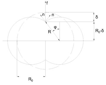
The value of f depends on the contact between the membrane and the cables. Generally, the more the cables press the membrane, the larger the force. The authors have developed a model to compute this force for the case with two parallel cables, which is applicable when the slenderness is very large. Under this assumption, as the cables penetrate the membrane, it deforms into two smaller circles as shown in Figure 10.
It is easy to see that f is the vertical projection of the normal forces n that act on the membrane:
|
|
(2.7) |
while, for each deformed circle, n is given by force equilibrium of half a circumference in the direction perpendicular to the cut, like in classic ring beam theory:
|
|
(2.8) |
In this model n depends only on R as the pressure is assumed constant. It follows then that the maximal hoop force will appear at midspan, when . The variation of the radius, if an inelastic membrane is assumed, is given by:
|
|
(2.9) |
|
| Figure 10: Membrane-cable interaction with parallel cables |
Putting equations 2.8 and 2.9 into 2.7 we obtain the expression:
|
|
(2.10) |
which can be also written in terms of the constriction of the cable in the membrane:
|
|
(2.11) |
The resulting expression can be linearly approximated around the origin as:
|
|
(2.12) |
And to the second order by:
|
|
(2.13) |
It can be shown that the first order approximation of f gives accurate results for and the second order one for .
Focusing on the case , the maximal contact force in the cable is
|
|
(2.14) |
which gives a maximal tension
|
|
(2.15) |
From force equilibrium of half a beam, it must be satisfied then that the maximum compression, at the centre of the strut, must also be .
Matching 2.15 with 2.4, we can find the needed pressure in the airbeam to support the external load q:
|
|
(2.16) |
Substituting this result in 2.8 with , we get the maximal hoop force that the membrane will have to withstand as a function of the external load:
|
|
(2.17) |
From force equilibrium at midspan it is satisfied that the strut suffers a compression equal to the tension in the cable. Consequently, buckling can happen at the strut. The strut lies on the membrane, which acts as an elastic foundation. The buckling load for a beam on elastic foundation is:
|
|
(2.18) |
where k is the stiffness of the elastic foundation and E and I are the elastic modulus and moment of inertia of the strut, respectively.
The value of k can be derived from the interaction between cable and membrane:
|
|
(2.19) |
This means that the buckling load can be controlled by adjusting the pressure in the airbeam. To avoid buckling it is enough to set EI such that P is greater than the compression in the strut. This is a great advantage with respect to classical structures as the material can be loaded up to its yield limit and not the buckling one, allowing a reduction of the useful section [15].
Let us call the yield stress of the strut and A its cross-sectional area. The maximum force that the strut can withstand is then . The maximum external load that the Tensairity beam can bear is then obtained by matching 2.4 with the yield force, resulting in:
|
|
(2.20) |
2.1.2 Displacement analysis
An expression for the displacement in the beam is also given in [13]. It assumes that the deflection is circular and large slenderness. Three components of the deflection are considered: the lengthening of the cable, the reduction of the strut and the reduction of the spiral radius:
|
|
(2.21) |
Here, is the strain of the cable and ; that of the strut.
2.2 Symmetrical spindle beam
In spite of the considerations previously made, buckling can happen in cylindrical Tensairity beams even if the cables, strut and air pressure are well designed. The formulation for buckling-free bending is based on a design in which the cables lie on the opposite site of the airbeam with respect to the strut. In cylindrical beams, this is true in their central parts but, as the cable approaches the supports, the spiral goes up and therefore both strut and cable lie above the neutral axis of the beam (Figure 9). As a consequence, the membrane pulls the strut downwards and buckling can happen in the extremes of the beam [16].
One way to avoid this is by setting the neutral axis at the same height of the supports. Alternatively, one can define a curve neutral axis that goes up as the cable does, maintaining symmetry between the strut and the cable at every section with respect to the axis. These solutions are called respectively symmetric and asymmetric spindle. A simple scheme of a symmetric spindle is shown in Figure 11.
|
| Figure 11: Symmetric spindle-shaped beam |
In these structures, the neutral axis is kept aligned with the supports and both the strut and the cable follow the same curve with respect to it. The shape of the curve that adapts better to uniformly distributed bending loads is the parabola, as the bending moment distribution is of this type. However and for most applications, a circular shape is used because it approximates the parabola while being simpler to model.
Apart from reducing the risk of buckling in the extremes of the beam, the spindle shape also increases its bending stiffness [16]. Besides, its symmetric shape allows using bending stiff members for the tension element too, so both positive and negative loads can be applied to the beam [17]. All these advantages have caused a further development of the analytical models to describe the structural behaviour of these structures compared to the cylindrical ones: [18] have studied symmetric spindle beams as columns, developing a model that describes the inflation of the hull and the axial compression separately. [4] and [19] have developed and solved analytical models based on ordinary differential equations considering and obviating the bending stiffness of the chords, respectively.
In the following, the models for inflation and uniform bending loading will be presented. A circular-shaped spindle is assumed in the first model, while the second one considers a parabolic shape.
2.2.1 Inflation of the beam
|
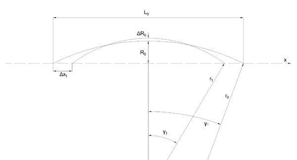
| Figure 12: Geometric changes due to inflation |
Imagine a hull of initial length under no loads but air pressure p due to inflation. The initial radius of the beam at midspan is . As shown in Equation 2.8, the hoop force depends on the pressure and the radius of the beam, so, assuming a constant distribution of in-plane stresses, the maximal hoop stress is:
|
|
(2.22) |
with t the thickness of the membrane.
For elastic elongations of the membrane, it is satisfied that:
|
|
so that, in the end:
|
|
(2.23) |
with E the elastic modulus of the hull.
It is also assumed that the cable and strut do not change their length during inflation. If is their length before inflating the beam and is that after inflation, then:
|
|
(2.24) |
From geometric considerations, the radii at midspan can be expressed as:
|
|
(2.25) |
And considering that and , one can solve 2.24 and 2.25 for and . The result for a first order approximation is:
|
With these quantities it is possible to compute the axial shortening of the airbeam:
|
|
(2.28) |
which is approximated to the first order as:
|
|
(2.29) |
A further approximation can be made if one assumes that the arch defining the spindle is almost flat. If this is done, then:
|
|
(2.30) |
and, finally,
|
|
(2.31) |
2.2.1.1 Stresses due to inflation
Regarding stresses generated during inflation, they can be computed through the expressions [17]:
|
|
(2.32) |
|
|
(2.33) |
where is the longitudinal stress, is the hoop one and the geometric parameters are those of the undeformed shape as already defined in Figure 12. These expressions are valid for any circular-shaped spindle, be it symmetric or asymmetric, and also for spindles that do not have end points but circular sections at the extremes.
These last expressions can be simplified for very slender beams, in which , to the form:
|
|
(2.34) |
|
|
(2.35) |
From Equations 2.32 and 2.33 and comparing with the stresses in a cylindrical tube, we see that stresses in a spindle are equal or lower than in a cylinder for the same radius and pressure [17].
The values and correspond to stresses assuming unit thickness of the membrane or, alternativey, to stresses integrated through its thickness. For any other membrane, the expressions can be rewritten as:
|
|
(2.36) |
|
|
(2.37) |
2.2.2 External uniformly distributed load
Authors [19] and [4] propose the same equations to solve the problem of the symmetric spindle under uniformly distributed loads. However, the first ones eliminate the bending stiffness of the chords off the equations, so that their solution is a particular case of the one given by [4]. This is the reason why only the complete case is presented here.
Such model consists of two beams -the strut and chord- coupled by an elastic foundation -the membrane-. The two chords are equal, symmetric with respect to the neutral axis of the beam () and follow a parabola, which can be described in the form
|
|
(2.38) |

|
| Figure 13: Geometric description of the parabolic spindle beam |
The differential equations that define the model are:
|
These are equilibrium equations imposed to differential elements in the upper and lower chords, respectively. As one can deduce from the equations, only the upper chord is assumed to be loaded with a load q. In these equations, EI is the bending stiffness of the chords, H is the horizontal component of the forces that arise in the chords, and k and G are the linear stiffness and shear modulus of the membrane, respectively. The equations are solved in and , which are the vertical displacements of the chords in the positive direction of z.
The properties of the membrane are considered constant in all the geometry for a given pressure and are computed as:
|
The problem is solved imposing symmetry along the z axis - so that only the right half of the beam is studied - and the following boundary conditions:
|
|
(2.43) |
The horizontal force in the chords is found by imposing that both chords suffer the same change in length as they are tied at the extremes of the beam:
|
|
(2.44) |
where A is the cross-sectional area of a chord. The values
|
|
(2.45) |
are the length of the chords.
To solve the system given by 2.39 and 2.40 with boundary conditions 2.43, an initial guess is made, with:
|
|
(2.46) |
which yields a result for and . At the same time, these values allow us to go to 2.44 and find a new H for the next iteration. The process is repeated until convergence is reached. The initial guess of H in Equation 2.46 corresponds to the analytical value of the tension at the cables in cylindrical beams (Equation 2.4).
The same authors propose different simplifications of this model to reach easier analytical solutions. One of them, of special interest in this work, is presented next.
2.2.2.1 ODE8 model
Introducing the hypothesis that the membrane has no resistance to out-of-plane forces; that is, , Equation 2.39 can be solved for , obtaining:
|
|
(2.47) |
This result can be introduced into 2.40, which then takes the form:
|
|
(2.48) |
with
|
Equation 2.48 is solved by imposing symmetry along the z axis again. The result is shown in Equation 2.51.
|
|
(2.51) |
The coefficients are determined through the boundary conditions given in 2.43, except for , which is:
|
|
These equations are also solved by iterating for different values of H found through 2.44 until convergence is reached.
The main advantage of this formulation is that it lets us know a priori the maximum load that the beam can withstand. This critical load is:
|
|
(2.52) |
where and is the slenderness of the beam, which can be computed now as .
Although it is possible to give closed expressions of the constants , the displacements and their integrals as a function of H, the resulting equations are too lengthy and symbolic representation and computation of these quantities is advised. All the same, Equation 2.44 can only be solved numerically.
2.3 Asymmetric spindle beam

|
| Figure 14: Asymmetric spindle with straight tension element |
As seen in Equation 2.6, the larger the curvature radius, the larger the tension in the cable for a given constant force. Therefore, a straight line in the tensional element is the shape that maximises the stiffness of the beam [16]. This fact explains the appearance of the asymmetric spindle (Figure 14).
In this type of beam, similarly to what happens in symmetrical spindles, the neutral axis lies above the tensional element and so buckling in the extremes of the beam is avoided. Besides, a straight tensional member gives the advantage of additional safety against deflation: it can be easily prestressed so that it withstands dead loads even if zero pressure is applied [17]. This feature is not useful for a deployable emergency footbridge, though. The final solution should avoid prestressing while ensuring resistance against dead loads.
Another problem with prestressing is that the tensional member would be subjected to large stresses once live loads act as well. In a footbridge, where one could expect mainly vertical loads pointing downwards, the best option is to use a material that stands tension only, not compression, like a wire or a loading belt. The stress this element can take depends on the material but, thinking in economic terms, it may be a good idea to reduce these stresses and reduce the amount of material needed.

|
| Figure 15: Asymmetric spindle with curved tension element |
One way to do this is by inverting the scheme of the asymmetric spindle, as shown in 15. Curvature in the tension element reduces its stresses, and so reducing the stiffness of the beam as well. At the same time, the compression element becomes straight, adapting worse to bending under uniformly distributed loads.
The behaviour of this type of structure is studied analytically and empirically in [20]. The resulting analytical model is presented next.
2.3.1 Analytical model under distributed load
Similarly to the case of the symmetric spindle, the structure is studied as two beams supported and coupled by an elastic medium.
The spindle is symmetric with respect to an axis perpendicular to the lines of the supports. The length of half a spindle is . The tensional element is assumed to have a parabolic form described by the curve , which follows the same expression as in Equation 2.38. The value of corresponds to the diameter at midspan of the beam. All these quantities can be seen in Figure 16.

|
| Figure 16: Geometric description of an asymmetric spindle |
The governing equations of the problem describe beams coupled by an elastic membrane, with the further hypothesis that the hull does not withstand shear stresses. They are:
|
with the same notation as for the symmetric spindle. The value of k is also the same as for the symmetric spindle, following Equation 2.41.
The process for solving these equations is also given in [20]; here we will just present the results:
|
Unlike in the symmetric case, the parameter is defined as:
|
|
(2.57) |
and the integration constants are:
|
The solution of the system depends on the value of the horizontal force H, which is computed through imposing that the change of length of the cable is due to this force. Mathematically:
|
|
(2.62) |
Here, is the axial stiffness of the cable and is the initial cable length. Equation 2.62 neglects the reduction of length of the strut, since it is considered to have a much larger cross section than the wire. The integral in 2.62 can be solved analytically, yielding:
|
|
(2.63) |
Like in the symmetric case, the analytical model is valid only if , which gives a condition for a maximum admissible horizontal force , with
|
|
(2.64) |
Approximating the value of H by the one that appears in a cylindrical beam,
|
|
(2.65) |
it is possible to estimate a maximum admissible uniform load on the beam:
|
|
(2.66) |
2.4 Computational models
The analytical models presented in the previous sections let us understand the main concepts governing the behaviour of a Tensairity beam. However, all of them are developed under simplifying hypotheses, such as the assumption of constant pressure after inflation or the coupling of tension and compression elements by a perfectly elastic medium. For this reason, displacements and stresses can only be computed analytically in a limited number of beam types.
Other problems in applying the analytical models are, for example, that the symmetric spindle can only be studied if the same material properties are used for the top and bottom parts of the beam. Instead, for the asymmetrical spindle, the material properties of the tensional element are ignored. Besides, cross sections of the airbeam are always circular and only uniform loads are considered.
These reasons make it necessary to create numerical models when a detailed analysis of the beam is needed [16], as in the design of the Tensairity footbridge.
In this work, only static load scenarios are considered. Following the recommendations in [16], only elastic models will be used. This is due to the static determinacy of the beam, which prevents any redistribution of stresses in the beam after failure of one of its parts. Therefore, failure verifications are performed simply by checking that stresses are in the acceptable range of the material.
Loading is applied in two consecutive steps. The first step represents the inflation of the beam, with two loads acting on the structure: self-weight and air pressure. Air pressure is modelled as a surface load acting perpendicularly to the membrane. The second step represents the external loading of the beam.
The order in which these loads are applied follows the real sequence in the deployment of the structure. This order affects the final result of the analysis and so it must be kept, since non-linearity is considered. This non-linearity arises from two sources in this type of problem. Namely, geometric non-linearity, especially during inflation of the hull, and non-linearity from contact forces are expected.
There are three main parts in the computational model of a Tensairity beam, same as in the analytical models. They are the compression element, the hull and the chords.
2.4.1 Compression element
The compression element, which is the deck in the footbridge, is modelled as a shell. Its mesh is composed of S4R elements: 4-node elements with curvature and reduced integration. This option is appropriate when the deck is in direct contact with the hull. If kernels were added, they should be modelled with 1D beam elements. This last element type is used also for Tensairity beams with no deck, having only a strut.
The initial geometry of the deck is the one expected after inflation. During inflation, the deck acts as a slave of the hull and so it deforms according to its contact with the hull. In order to model this step correctly, the hull needs to be described initially with its inflated geometry.
Boundary conditions, which are simple supports, are modelled in the deck. This is done by blocking the degrees of freedom of the nodes that correspond to the supported surface. The extremes of the tensional element, which should join the deck at the supports, interact with the deck as slave nodes.
2.4.2 Hull
The hull is the most problematic part to be modelled. Properties of the inflating hull vary in practice from one manufacturer to the next one. Here, since Buildair buys its fabric from the same provider, its behaviour is well-known and, based on this previous experience, the hull is modelled as an isotropic membrane. The original material is actually woven differently in the longitudinal and transversal directions but the manufacturer prestresses the transversal threads, so the membrane behaves equally in both directions.
Membrane elements are used to mesh the hull. In particular, M3DR4 elements are used, which also have 4 nodes and reduced integration.
The shape of the hull influences the type of analysis performed on the structure. It was observed that static analyses reached convergence when the hull had circular cross section. For more complex shapes, quasi-static analyses had to be performed. Besides, including the extremes of the hull in the model has been proven by past experiences to complicate further the convergence of the problem. These parts of the structure are not important for the analysis and have been eliminated off the model.
A quasi-static analysis is a type of dynamic analysis in which the loads are applied so slowly that ignoring inertia forces does not affect the solution of the problem. The Finite Element solver applies the load linearly over the total time of analysis and then it evaluates the solution at time increments such that the load increase does not cause inertial effects.
Unlike in purely static analyses, time derivatives are involved in the solution. This increases the computational effort for the solver but allows to include damping in the model. As a result, convergence is reached more easily than in static problems, so this type of analysis is suited for problems with complex contact and deformation conditions.
Convergence is hard to reach in these problems during the inflation phase, as the hull is loaded perpendicularly to its surface, while membrane elements bear only in-plane stresses. To solve this issue, [16] proposed including an elastic element perpendicular to the membrane at each of its nodes, so that some artificial bending stiffness appears in the membrane. Instead of doing so, the analyses performed here implemented the stress stiffening property of membrane elements, which gives bending resistance to the membrane as in-plane stresses grow.
To understand this property, we can think of a paper sheet. Initially, the sheet is very soft and deforms very easily. However, if we pull from its extremes, the sheet becomes straight and is able to withstand perpendicular loads. The stress stiffening property can only be included if a non-linear analysis is performed, since the stiffness increase is computed iteratively from the previous equilibrium state.
2.4.3 Tensional element
The tensional element is modelled either with membrane (M3DR4) or 1D truss (T3D2) elements, depending if it is a belt (in which case some width has to be taken into account) or a wire.
|
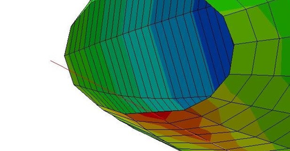
| Figure 17: Example of chord penetrating the hull in a computational model |
Penetration of the tensional element into the hull, especially if it is a wire, is very important for obtaining correct results. This penetration governs the coupling between the strut and the chord and determines the stress level in the chord. Therefore, it is crucial to model correctly the contact between these parts.
All the models built here have been drawn with high precision via CAD and the geometry exported later to a FE solver. This high precision, together with a fine mesh, allow to define which elements are initially in contact. The software then couples the nodes that come closer than a given tolerance once the model starts deforming.
In all cases, even though we have talked about contact, the interaction between structural elements is not defined through this tool in the Finite Element solver. Instead, these were modelled as ties between adjacent nodes. Ties assign the same values of nodal displacement to the slave node as to the master node. This choice was taken instead of modelling friction for two reasons: advice from an engineer working on similar projects and the lack of data regarding the tangential friction coefficient for any of the materials used. The result of this choice can be seen in Figure 17, which represents the penetration of a wire into a hull.
2.5 Deployable structures
All the models and schemes presented this far have assumed that the strut or compression element is continuous and formed by a single piece. However, these structures do not take full profit of the advantages that Tensairity beams present. With a correct dimensioning and material choice for the tension and compression elements, Tensairity structures can be much lighter than traditional ones, for the same length of the beam.
This lightness, together with the reduction of volume after deflation and the easy division of the structure in different components, make Tensairity appropriate to design deployable structures, such as the footbridge object of this work. Nonetheless, a continuous and rigid strut makes it hard to transport the beam.
The most immediate idea to lose rigidity in the strut is to include pin joints along it. However, these structures are not able to bear external loads. The basic structural scheme of the Tensairity beam is an isostatic beam. Including any joint causes the beam to become a mechanism and collapse under any load, at least if no resistance of the hull is considered.
The actual behaviour of the pin-jointed beam differs from the expected mechanism because the hull has indeed some -small- shear resistance [17] and so the system can still bear some load. All the same, the pin-jointed sections are weakness points of the structure and large deflections are expected. In chap:chapter3 and chap:chapter4 the shear resistance of the hull is ignored, for simplicity and based on previous works in Buildair.
In order to reduce the large deflections while allowing the deployment of the beam, [21] have studied different strut systems with different deployment mechanisms and have characterised their behaviour under external loads.
A deployable Tensairity structure is defined as "a Tensairity structure which can be folded or rolled together when deflated to a compact configuration without disassembling the different components it is constituted of" [22]. In [21], three different methods are proposed to achieve that.
The first method consists of a segmented compression element. This strut is formed by several rigid members joined by a textile hinge in their lower sides, as illustrated in Figure 18. In this way, the strut can be folded in the side of the hinge but will have hard contact between stiff members when bending it to the other side. This strut is then bending stiff only if loaded on the appropriate side.
 ] ]
|
| Figure 18: Segmented strut with textile hinge. Extracted from [21] |
The correct positioning of this strut would then have the textile hinge in contact with the hull, so that it can adapt to its changing shape during inflation. External loads can only be applied on the opposite side then. Furthermore, this system is not appropriate for strictly symmetric designs, since it should have another strut on the opposite side of the hull and folding would not be possible.
The second method is the triangulated cylinder. This concept is still in early development and it still needs to be tested in a prototype. The idea is to generate a cylinder made of a mesh of triangles. This mesh collapses into a stack of planar layers.
The cylinder should be composed of a 'wire' net, each 'wire' following a helical curve. This network, however, works as the compression element of the beam and thus the material should be bending stiff, although it must keep some flexibility. Then, a membrane fills the gaps between wires. Obviously, the union between membrane and wire and the contact points of wires must be airtight. Figure 19 shows a digital representation of a possible configuration of a triangulated cylinder.
 ] ]
|
| Figure 19: Sketch of a triangulated cylinder with highlited compression element. Extracted from [21] |
The wire network acts as the compression element of the beam. The main advantage of this system would be the controlled shape of the deflated airbeam, which could ease the transport and packaging of the beam. Besides, the compression element is now really small and coupled with the membrane, so the size of the package is reduced when compared to a regular strut. On the other hand, this system does not allow to walk comfortably on it, so it would need an additional walkway that would bring back the problem of transportation.
The third method is the foldable truss. This truss is characterised by having hinges along the compression and tension segments. The result is a mechanism that can be overlapped and so it reduces its volume when folded.
The foldable truss is placed inside the airbeam. When inflated, the internal pressure pulls the mechanisms and gives rigidity to the hinges, so the truss is able to bear loads. For this to happen, the truss must be continuously joined to the membrane.
In order to increase the stiffness of the system, cables can be added to join the compression and tension elements. These are loose when the beam is deflated and so they do not disturb the folding process, while they become tensioned when the truss strut and tension element are straight.
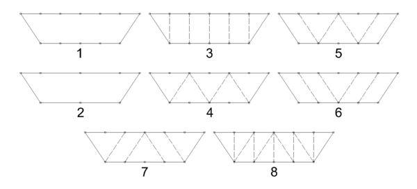
In [21], various truss systems were tested inside a cylindrical beam. These had different geometries, as seen in Figure 20. The number of hinges, internal pressure and pretension level of the cables was altered as well to check their influence in the stiffness of the system.
The results of these tests can be seen in detail in their paper. Here, we will just focus on the general conclusions from their tests. First and similarly to what is observed in ordinary Tensairity beams, the higher the pressure, the stiffer the structure. This is due to the increase of tension in the membrane, which increases the tension in the cables as well, and the larger friction between strut and membrane.
 ] ]
|
| Figure 20: Different truss systems tested in [21] |
As seen in Figure 20, trusses with different number of hinges (numbers 1 and 2 of Figure 20) were tested. Surprisingly, the number of hinges does not have great effect on the stiffness of the structure. However, the two trusses tested in [21] have hinges at midspan. In [22], some extra tests were performed, one on a truss without central hinge. The results with both local and distributed loads showed that this truss was much stiffer than the others, indicating that the presence of the central hinge is the most decisive factor in the level of stiffness of a deployable truss.
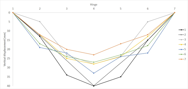
Trusses 3 to 8 of Figure 20 have the same number of hinges but different internal cable layouts. Performing the same loading tests on these trusses lets us observe the influence of the cable layout. Figure 21 shows the vertical displacement of different trusses with the layouts of Figure 20. These results were obtained for 2 m long beams with a maximum distance of 50 cm between the compression and tensional bars when a force of 6 kN is distributed on every hinge of the beam.
 ] ]
|
| Figure 21: Vertical displacement at hinges for different cable layouts. Adapted from [21] |
In Figure 21, each cable layout is represented with a different colour and, besides, the cases in which no cable is present is shown in black for the sake of comparison. The discontinuous line indicates the case with fewer hinges along the compression and tension sides (case 2 in Figure 20). The identifier of the hinges in the plot runs from 1 corresponding to the one at the left support to 7 at the right support.
The test results for the eighth truss are not provided in [21] but for the rest we can see that the seventh is the stiffest one. However, it is necessary to remark that all these trusses have pinned joints at midspan, and probably other configurations lacking this central joint would be stiffer than these ones.
The different folding mechanisms for deployable Tensairity beams have been presented. Nonetheless, the triangulated cylinder still needs a valid prototype to be tested and understood. Therefore, when thinking about a deployable footbridge for emergencies, we will consider only the two remaining options: the segmented compression element and the foldable truss.
The main problems of the foldable truss for its application in an emergency footbridge are that it increases the total weight of the structure and its cost compared to the segmented strut. Weight is in fact a critical issue in this structure and so it is worth focusing more on a segmented compression element.
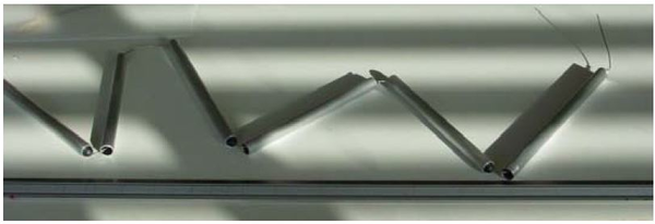
In [22], different materials are tested for the segmented strut. One of them has already been shown in Figure 18. In that case, a composite section is used, with aluminium in the contact surface with the external loads and wood -which is lighter and less resistant- under it. Other options considered are a segmented pipe, a chain, an inflated hose and wooden blocks.
 ] ]
|
| Figure 22: Segmented pipe used in [22] |
The last option is very similar to the composite section but leaving out the aluminium on the top side and the textile hinge on the bottom side. Both of these systems perform well under high distributed loads, with similar stiffness than continuous struts with the same materials. When the external load is small, the compression in the segments is not enough to press them and shear cannot be transmitted along the strut. The same problem arises when local loads are applied instead of distributed ones. In this situation, the compression element fails by buckling of its segments.
The segmented pipe works with the same principle as the ones before. The segments are joined by a wire, as seen in Figure 22, that compresses them when it is tensioned, but it lets them loose when no tension is applied. In their experiment, [22] used a thin circular aluminium pipe. This shape is not appropriate for bearing loads as high stresses concentrate in the point of application, and the prototype buckled in that point with a small load.
Another investigated option is the chain. The test results are not promising at all, as the chain buckles at low loads in both the distributed and local load cases and regardless of the orientation of the pins.
Finally, two different hoses were tested. The idea behind this element choice is to have a foldable and flexible strut, easy to transport, which can then be pressurised and thus stiffened. One of them was composed by a steel tube covered by rubber, as seen on the right of Figure 23. This system fails under small loads since the rubber and the steel have bad contact. Instead, the other one, a simple plastic hose, showed relatively good performance when it was inflated to a high pressure: 8 bars in the experiment. With this overpressure, the beam could bear twice as load as the airbeam without any strut and tensional element.
Besides, this last hose was filled twice, once with air and once with water until the same pressure was reached. The same results were obtained in the loading test, so we can conclude that the load bearing capacity is independent from the fluid as it is the rubber the one carrying the load.
 ] ]
|
| Figure 23: Hoses used in [22] |
Out of the tested systems, only the inflated hose and the segmented trusses showed a good-enough performance for future applications. The hose, nonetheless, only improved a 100% the load carrying capacity of the classical airbeam. For comparison with any other system, Table 1 shows the maximum beared load for each system, the reason for failure and the deflection at that moment. Blank cells are as found in the original.
The folding hose could be an appropriate choice for applications in which the external load is distributed and small. The segmented strut, though, is a better choice in terms of load carrying capacity and, between the wooden and the composite struts, the composite one stands out as the best choice for future developments.
In any case, the range of application of the segmented strut is limited since its behaviour under local load is not satisfactory, suffering from buckling even when it lays on an inflated airbeam. Besides, and thinking about its use in a footbridge, a compressed strut is not sufficient for carrying people; a walkway is still needed. For these reasons, the proposed footbridge will not be strictly deployable but modular. And from the results obtained here, a composite material will be proposed as its walkway.
There is no bibliography dedicated to the study of modular inflatable beams, and so the next fourth chapter will focus on the development of our own design. The notions gained in this chapter will be used to create a proposal for a modular footbridge which will be then built and tested, as "The exploration and analysis of ideas for deployable systems by means of experiments on scale models is the recommended method to evaluate proposals and gain understanding of the influence of different parameters" [22].
| Folding system | Load at failure [kg] | Deflection [cm] | Failure mode [] |
| Airbeam | 18 | 5 | - |
| Continuous wooden strut | 70 | 3 | Material yield |
| Segmented wooden strut | 48 | - | Buckling |
| Segmented composite strut | 60 | 5 | Material yield |
| Segmented pipe | 45 | - | Buckling |
| Chain | 30 | - | Buckling |
| Steel and rubber hose | 30 | 5 | Pressure limit |
| Folding hose | 37 | 5 | Pressure limit |
3. Preliminary studies
In order to clarify the theoretical concepts and models presented in chap:chapter2, different computational models have been produced and studied in Abaqus2mm. These models do not serve for design purposes but as first hands-on approaches to the computation of Tensairity structures. Nonetheless, some conclusions might be useful to decide the best geometry for a final design.
First, beams with only one hull are computed. Simple materials and structural elements -beams- are used as to make possible their comparison with the analytical solution. Later, more complex structures are solved. They include composite materials and shell parts, with more complex interactions among the elements.
3.1 Single-tubed footbridges
Two beams with a single tube have been solved. Each one has only three different structural elements: the hull, the strut and the chord. The first one is modelled through membrane elements, while the other two are modelled as beam elements. All beams have circular cross-section with 2 cm radius. The extremes of the beam elements are tied together, also rotationally, as to model the effects of the end parts of an actual Tensairity beam. Table 2 sums up the material properties of said structural elements. Both of them are commercially available.
| Structural element | Material | E [MPa] | |
| Hull | Membrane | 1045 | 0.235 |
| Chord | Steel | 160000 | 0.3 |
One of the beams follows the scheme of a symmetric spindle, while the other one is an asymmetric one with a flat upper side. In both cases, it is satisfied that:
- The length between the two supports is 6 m.
- The beam is simply supported, with free longitudinal displacement at .
- The hull has circular cross-section with a maximum diameter at midspan of 60 cm, resulting in a ratio diameter at midspan/length equal to 0.1.
- The spindles follow a parabola in the longitudinal direction, given by the two supports and the radius of the hull at midspan.
- The beam elements are in tight contact with the hull.
Besides, all materials are elastic and the external load is applied to the whole strut and it is equal to 100 kg/m. Internal pressure, on the other hand, is 105 mbar.
The same beams have been calculated analytically in parallel following the ODE8 models described in the previous chapter. The models are implemented in scripts written for Matlab2mm v2015. The scripts are copied entirely in appex:appendixA.
3.1.1 Symmetric spindle
Figure 24 shows the longitudinal profile of the symmetric spindle taken as example for this exercise.

|
| Figure 24: Longitudinal profile of the single-tubed symmetric spindle |
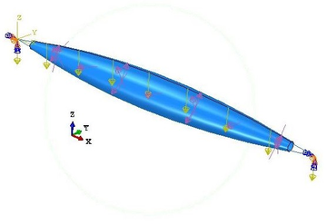
The beam is solved in two consecutive steps: inflation and loading. In these exercises, in order to get a problem as similar as possible to the analytical model proposed in [19], self-weight is not considered. The applied loads appear in Figure 25. Internal pressure, in purple, is applied to the insides of the membrane, while the line load is applied to the whole length of the strut.
|
| Figure 25: Loads in the single-tubed symmetric spindle |
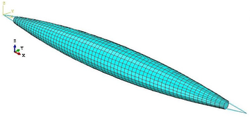
Each part of the model has been meshed independently. In the hull, in order to maintain the curved shapes, the borders at the extremes are seeded finer than the generatrix. In particular, a node is placed every 8 cm approximately in the longitudinal direction and every 2 cm in the extreme borders. In the cables, each node is separated 4 cm approximately. This distance is enough to keep a good approximation of the initial parabolic shape. The resulting mesh is shown in Figure 26.
|
| Figure 26: Mesh in the single-tubed symmetric spindle |
The solution process, divided into two steps, is not only necessary to correctly account for the non-linear effects induced by the inflation of the hull; it is also useful to check the status of the beam also when there are no external loads acting yet.
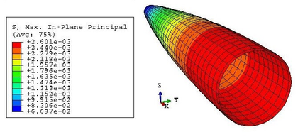
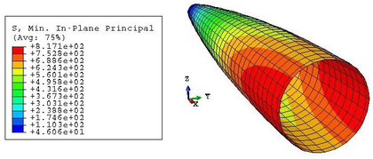
Then, the results of this first step can be compared with the mathematical development of subsec:Inflation of the beam. For example, focusing on the stresses in the membrane, the analytical model assumed a constant distribution of value given in Equation 2.22. This hypothesis is conservative and, as seen in Figures 27 and 28, it overestimates the stress state of the hull. Equation 2.22 predicts a hull stress equal to:
|
|
|
| Figure 27: Symmetric single-tubed beam. Max. in-plane stresses after inflation |
|
| Figure 28: Symmetric single-tubed beam. Min. in-plane stresses after inflation |
This value is very similar to the maximum in-plane stress of the membrane, equal to 2610 kPa. However, this value corresponds only to the maximum of the maximum in-plane stress distribution. This maximum is kept constant in the nodes corresponding to the same cross-section, but it diminishes as we go far from the centre of the beam. Besides, the stresses in a point depend also on the direction, as proven by the values of Figure 28, different from the maxima.
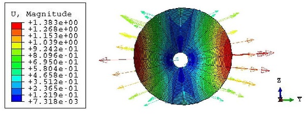
The increment of radius predicted in Equation 2.23, which is equal to 0.75 mm, differs from the actual change of shape experienced by the hull. This is due to the fact that the analytical model does not account for the interaction between the membrane and the beam elements. After inflation, the radius at midspan is actually lower than , as seen in Figure 29. The elongation of the beam cannot be predicted with the analytical model presented in subsec:Inflation of the beam as the membrane does not end in the supports.
|
| Figure 29: Symmetric single-tubed beam. Displacements at midspan after inflation |
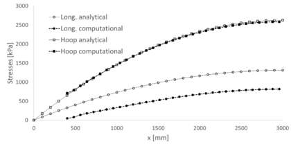
The stress state of the airbeam after inflation can be computed more accurately through Equations 2.36 and 2.37. The results are shown for half a beam in Figure 30. There, for the analytical curves, the longitudinal stresses are simply half of the hoop ones at every section. This Figure allows us to compare the analytical results with the ones obtained numerically, which are shown in a discontinuous line. We can see that the hoop stresses show close results in both models, while the longitudinal stresses differ more; being lower in the computational model. The curves from the computational models do not start at because the hull does not collapse into a point at the support; it ends 40 cm before.
|
| Figure 30: Symmetric single-tubed beam. Stresses along the midline after inflation |
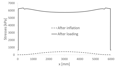
The second step of the numerical model represents the application of a uniformly distributed load along the strut, with magnitude equal to 100 kg/m. The loading process is the responsible for most of the stresses in the beam elements. During inflation they do not suffer much, as shown in a discontinuous line in Figure 31 for the tensional element. This Figure represents the maximum stress field - its tension - in the chord for both steps. After loading, the tension in the chord is represented by the continuous line.
|
| Figure 31: Symmetric single-tubed beam. Tension along the chord |
We can see that the tension at midspan grows more than ten times its original value after applying the load. Besides, the maximum value is not at midspan, as it happened after inflation, but at the last point of contact between the chord and the membrane - around and . At those points, the tension is equal to 6345 kPa. Another important aspect of those curves is that, in either case, the extremes of the chord are subject to small tensions, null during inflation in fact. This result is valid for the inflation phase, as we have seen that stresses in the membrane, which are then passed to the chord, are dependent on the radius and so they diminish near the supports. However, the sudden drop after loading should be looked at carefully.
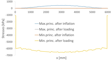
The same plot can be seen in Figure 32 for the strut. In this case, the maximum and minimum principal stresses are shown, even if mostly compressions -negative stresses- are expected. Both the stress state after inflation and after loading are represented, but the minimum after inflation and the maximum after loading cannot be seen as they collapse to the axis of the plot in the vicinity of zero stress. In other words, the strut bears no compression during inflation and no tension after loading.
|
| Figure 32: Symmetric single-tubed beam. Stresses along the strut |
The stress state after loading is different from its counterpart in the tensional element. First of all, the value of the compression at the extreme is equal to the value of the tension in the extremes of the chord, as required by nodal equilibrium. For the rest, the curve grows almost monotonically as we approach the centre of the beam, although there is some alteration in the vicinity of the extremes of the membrane.
The maximum compression has a value of 6586 kPa. Note that this value differs from the maximum tension at the chord. As stated in chap:chapter2, the compression force in the strut must equal the tensional one in the chord at midspan. If the beam elements were considered completely rigid, this equation would be satisfied also for the stresses. However, the numerical model takes into account cross-sectional deformability and so the stresses change. Besides, flexion effects are introduced in the tensional element, which is usually considered as being capable of bearing tension only.
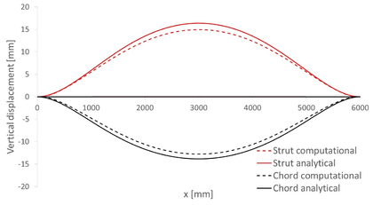
Regarding displacements, it is possible to compare the numerical results and the ones provided after solving the ODE8 model in Matlab. For that purpose, it must be considered in the computational model that the geometry after inflation is the initial one, so displacements must be relative to the deformed state of the first step. The numerical results are shown in Figure 33. The discontinuous red line represents the displacements in the strut, while the black one corresponds to the chord. As seen there, the maximum displacement corresponds to the centre of the strut and it is equal to 1.45 cm, directed downwards.
|
| Figure 33: Symmetric single-tubed beam. Vertical displacements due to loading |
The same Figure also shows the displacements from the analytical model. The reference system has been transformed to coincide with the one from the computational model. A downwards displacement is considered positive, so both plots agree in this aspect. The maximum displacement in the strut in this case is 1.64 cm, which represents a difference of a 13.1% with respect to the numerical value. This is an acceptable difference given the small entity of the displacements - both models differ only 3 mm - and so the numerical model is considered valid.
3.1.2 Assymetric spindle
With similar characteristics as the symmetric spindle of the previous section, an asymmetric spindle is studied now. Its geometry is such that all cross-sections have their top point aligned horizontally. These cross-sections are circular, resulting in an asymmetric spindle with curved tension member and straight strut. The resulting profile is shown in Figure 34.

|
| Figure 34: Asymmetric single-tubed beam. Profile |
The procedure to study this beam follows the same steps as the previous one; that is, an increment of the internal pressure is applied first and then a vertical line load acts along the strut.
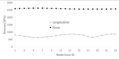
The stresses in the membrane after inflation follow the same expressions as the symmetric case, as they are applicable to any vessel with circular cross-section. Therefore, their analytical determination follows Equations 2.36 and 2.37. We can check that, as in the last case, the numerical results adjust very well to its analytical counterpart, while the longitudinal stress is lower. As an example, Figure 35 shows these stresses at the central cross-section of the membrane. The hoop stress, plotted with filled markers at each node, is almost constant in the numerical model and oscillates around a value close to 2600 kPa, almost coincident with the predicted 2625 kPa of the analytical expression. The longitudinal stress, on the other hand, has larger oscillations around a value lower than the expected 1312.5 kPa. Only the central part of the plot curve is close to that value, although still lower.
|
| Figure 35: Asymmetric single-tubed beam. Membrane stresses after inflation at midspan |
Regarding displacements, it is remarkable that the inflation process provokes almost no movements in the beam elements. The vertical component of these displacements can be seen in Figure 36 for the strut and the cable. Furthermore, the cable moves downwards at the extremes of the beam. As a consequence, the penetration of the cable into the hull is almost null, reason why we can expect lower tensions there. This is explained through Equation 2.6, in which T is given, since the beam is isostatic and so for larger curvatures , the tension f in the cable is lower.
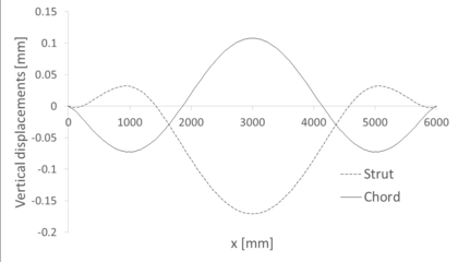
|
| Figure 36: Asymmetric single-tubed beam. Vertical displacement due to inflation in the beam elements |
As a result, the asymmetric spindle with curved cable is less stiff than the symmetric one. This is effectively checked in the displacements caused by the external load. Let us plot these results for the computational and analytical models (Figure 37).
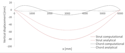
|
| Figure 37: Asymmetric single-tubed beam. Vertical displacement due to external loads in the beam elements |
The first thing to notice in this plot is that the cable is not lifted as tension increases. Instead, it goes down in its whole length according to the computational model, or in its central part, according to the analytical one. In any case, these displacements are still small, especially when compared to those in the strut. The maximum displacement achieved in the strut is 5.56 cm, which is 3.83 times larger than in the symmetric spindle. The overall behaviour of the beam is the same when the two models are compared. The main difference is found in the extremes of the cable, which go up according to the analytical model and down according to the numerical one. The centre moves downwards in both models. Moreover, and similarly to what happened in the symmetric case, the displacements in the computational model are lower than those of the analytical one. Taking as an example the displacement at the centre of the strut, we see that the analytical model yields 8.22 cm, that is, a 47.84% more than the computational model. This is a relevant difference, which may be explained partially by the augmented stiffness of the mesh, which represents the beam as four centimetre long segments with constant stresses and deformations along them.
All the same, the error between the two approaches is too large to ignore, creating an uncertainty in the capability of the chosen computational model to represent the actual problem.
3.2 Double-tubed footbridges
With the scope of introducing the modelling of more complex materials and structural interactions among elements, double-tubed beams have been designed and studied in Abaqus. Currently there are no models to describe the behaviour of these beams, so the study will include only computational results, which will be used to compare the fitness of each beam type to carry people. Three computational models have been created, each one corresponding to one of the shapes discussed before -symmetric and asymmetric spindles-. All these footbridges follow a similar scheme with a continuous walkway and two airbeams with a radius of 30 cm at midspan. In order to allow an easy comparison, they are all built with the same materials and main dimensions. The acting external loads are the same as well: an inner overpressure of 200 mbar and a uniformly distributed load over the walkway of 200 . Materials are commercially available for each part of the structure:
- The walkway is a sandwich panel consisting of three layers: a core in rigid polystyrene and skins of aluminium. Its thickness is 0.5+9+0.5mm.
- The membrane is a composite material already used for Buildair in other projects with satisfactory performance. It is composed of a web of high tenacity polyester coated with high performance polymers.
- The tensional element is a galvanised steel strand cable with a diameter of 6 mm.
Isotropic linear elastic constitutive laws are considered for all the materials involved. The values of the elastic constants for each material are given in 3.
The geometry of the bridges is given by:
- A ratio diameter at midspan/length equal to 0.1.
- A length of 6 m.
- A width of 1.2 m for the walkways.
As for the single-tubed beams, all curved shapes in the longitudinal direction of the footbridges are parabolas defined by three boundary conditions:
- The extremes and coincide with the supports.
- At midspan, the parabola touches the membrane and so it has its same height.
| Structural element | Material | E [MPa] | Density [] | |
| Deck | Aluminium | 69000 | 0.3 | 2700 |
| Deck | Foam | 69 | 0.3 | 55 |
| Hull | Membrane | 1045 | 0.235 | 1323 |
| Chord | Steel | 160000 | 0.2 | 7850 |
The geometry of all models has been developed in CAD and then exported to the Finite Element program. The walkway is originally divided into one-meter long segments in order to start testing the modelling of modular footbridges.
Like the single-tubed beams, these are solved in a two-step analysis. The first one is inflation but now includes the effect of the self-weight as well, which was ignored previously to adapt to the numerical model. The second step is again the external load, now imposed as a uniformly distributed pressure along the walkway. A static analysis has been performed, as no convergence issues appeared due to the relative simplicity of the models.
3.2.1 Symmetric spindle
The first double-beamed footbridge is built from two airbeams like the ones used in subsec:symmetric_spindle. The cables with a diameter of 6 mm are in tight contact with the lowermost points of the airbeams, and their extremes fall along the extreme lines of the walkway. These can be seen in Figure 38, which shows the profile of the footbridge. The extremes of the walkway serve now as a lineal support for the footbridge, as appreciated in Figure 39.
We can see in that last image that some portions of the airbeams overlap with the walkway and even hide it. This is an issue related to the image processing of Abaqus, but the real geometry as imported from CAD featured an exact coincidence between the two surfaces. This is proven in Figure 40.

|
| Figure 38: Symmetric double-tubed beam profile |

|
| Figure 39: Symmetric double-tubed beam top view |

|
| Figure 40: Symmetric double-tubed beam profile as designed in CAD |
Each module of the walkway is meshed separately and then an interaction to block the corresponding degrees of freedom at the shared borders is imposed. By doing so, the structure behaves as it had a continuous walkway, but eliminating the tie in the rotational degrees of freedom also allows to study the beam as pin-jointed.
Another tie is imposed in the touching points of the two airbeams to model their contact. This avoids overlapping of the two membranes when inflating, as it is expected that their sides grow. This hard contact makes that, once inflated, the membranes do not grow symmetrically in both lateral directions. Instead, they experience a slight rotation towards the exterior of the footbridge. This is clearly seen in the displacements of the nodes shown in Figure 41. The section shown corresponds to a transversal cut at midspan of the beam.
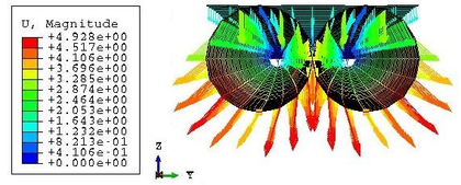
|
| Figure 41: Symmetric double-tubed beam. Displacements after inflation |
The impeded penetration between membranes is not relevant to the stress state of the airbeams after inflation. In practice, both membranes could have been studied separately. A proof for that is given in 42. It shows the hoop stresses acting on the most extreme nodes of the cut shown in the previous Figure. As already seen for the single-tubed cases, the stresses are nearly constant and close to the theoretical value of 5000 kPa in all nodes, so there is no difference between having or not contact between membranes during the inflation phase.
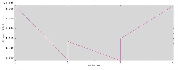
|
| Figure 42: Symmetric double-tubed beam. Hoop force along the central nodes at midspan during inflation |
An important difference with respect to the single-tubed cases is that now we can see the effects of the self-weight in the inflation. Now, the whole upper sides of the airbeams move downwards, while this only happened to the node closest to the strut before. This is due to the weight of the own membrane and also the walkway, which pushes them down.
After loading, the cables are the structural elements that bear more stresses. Before the external load is applied, the central part of the cables is the one that is more tensioned, mainly because it is the part of the beam with larger radius and so the hull transmits the most stresses there. However, the appearance of the uniform load changes this distribution.
First, we notice that tensions grow to values up to 450 MPa from the maximum of 55.16 MPa experienced before. Secondly, the maximum after loading is not in the centre of the cable. This is expected since now the increment is due to the transmission of forces from the walkway at the supports and not to a direct transmission through the membrane. As the curvature of the cable is higher when closer to the centre, then the stresses get lower in that area. A comparison of the stress state in any of the cables when only inflated and with the applied load can be seen in Figure 43.
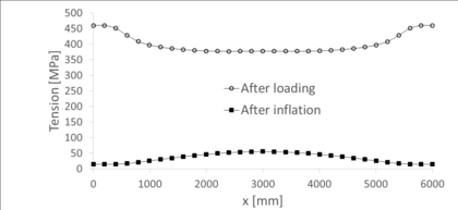
|
| Figure 43: Symmetric double-tubed beam. Stresses at the cables |
Regarding the membrane, the stresses do not vary much from inflation to loading states. This is in agreement with the theory, which tells that external forces are carried by the compression and tension elements, while the hull serves only as a support of the compression element and to pretension the tensional one [16]. In particular, the maximum principal tension changes from 4905 kPa to 4801 kPa, always at midspan.
Finally, regarding the walkway, the same phenomenon as in the cables happens: the most solicited zones of the element move from the centre (Figure 44) after inflation to the extremes after loading.

|
| Figure 44: Symmetric double-tubed beam. Min. principal stress at the walkway after inflation |

|
| Figure 45: Symmetric double-tubed beam. Max. principal stress at the walkway after loading |
In the final state, however, the maximum stresses are not right at the supports but slightly moved to the centre. In particular, the largest tensions concentrate right above the extremes of the membranes, where there is direct contact between them and the walkway. On the other hand, the largest compression is found in the end supports, where longitudinal movement is allowed. All the central part of the walkway works only in compression, while the extremes bear more tension. All this can be appreciated in Figures 45 and 46. Only stresses in the bottom layer of the walkway are taken into account in order to lighten this preliminary analysis.

|
| Figure 46: Symmetric double-tubed beam. Min. principal stress at the walkway after loading |
The vertical displacements of the central line of the walkway are shown in Figure 47. The blue line shows their distribution after loading, while the purple one shows the displacements caused by the loading alone, ignoring the inflation. In other words, the vertical displacements due to inflation are the difference between the two curves. As one can see there, this difference is very small, so the majority of the displacement can be associated to the effects of the loading. Nonetheless, the maximum displacement is only 3.5 cm, still greater than in the single-tubed beams. This is due to the larger load applied to the beam, even though the pressure is also larger now.
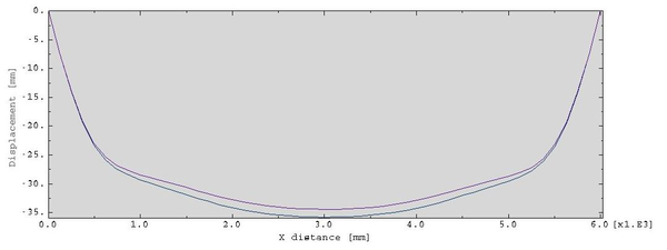
|
| Figure 47: Symmetric double-tubed beam. Vertical displacements along the walkway |
3.2.2 Asymmetric spindles
The results obtained for the symmetric spindle will be compared to the ones shown in Figures 48a and 48. Our focus will be on the loaded state, since inflation is similar in every case studied so far and there is no point in repeating the information.
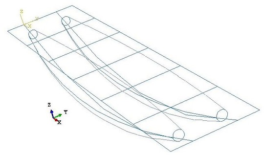
|
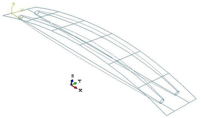
|
| (a) Flat asymmetric double-tubed beam | (b) Curved asymmetric double-tubed beam |
| Figure 48 | |
The different layouts, with null curvature of the walkway in the flat asymmetric spindle and larger curvature in the curved one, create a new distribution of stresses in each case. These were not compared in the single-tubed footbridges, as only the flat one was studied. Now, it is possible to check by comparing Figure 49 with Figure 43., that the chords in the flat spindle suffer greater tensions than those from the symmetric one, while the curved spindle is the one that bears the smallest tensions.
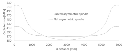
|
| Figure 49: Asymmetric double-tubed beams. Tension in the cables after loading |
All cases share that the greatest tensions in the chords appear near the extremes, being the largest in the flat spindle, with a value of 5.18 MPa. The cable of the curved spindle, with curvature constant and equal to zero, has also the flattest distribution of stresses. However, a slight increase is still noticed, as in the other cases. This increase corresponds to the 12.95% with respect to the value at midspan: 4.18 vs. 3.70 MPa. This increment is greater than a 46% in the flat asymmetric spindle and close to the 21% in the symmetric one.

|
| Figure 50: Flat asymmetric double-tubed beam. Tensional state in the walkway after loading |

|
| Figure 51: Curved asymmetric double-tubed beam. Tensional state in the walkway after loading |
In the walkway, on the other hand, stresses are generally lower in the curved spindle than in the flat one. This is due to the parabolic shape of the upper part of the beam, which follows the bending moment distribution of the isostatic beam. As seen in Figures 50 and 51, only the compression generated in the extreme of the beam due to the connection with the cable is larger in the curved spindle. The largest difference arises in the tensions generated at the end of the contact with the airbeams, which are seven times larger in the flat spindle than in the curved one.
In order to compare the magnitude of the principal stresses more clearly and obviating the extreme values given by the contacts with the chords, Figure 52 shows the stresses at the nodes of the midline of the walkway for both the flat and curved spindles. Here, we see more clearly that the whole length of the walkways suffer some compression, but also that tensions appear, and with large magnitudes, when the membrane below disappears.
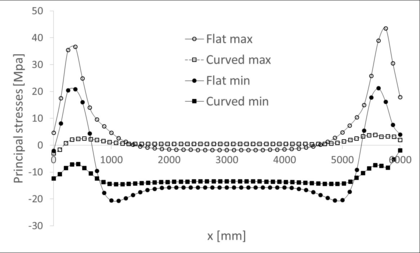
|
| Figure 52: Asymmetric double-tubed beam. Tensional state in the walkways after loading |
The larger stress level in the flat spindle is accompanied also by larger displacements on the beam. Indeed, the structure being less stiff than in the other geometries, the strut moves more under the same load, as demonstrated in Figure 53. The maximum displacement, which occurs at midspan, is equal to 6.9 mm in the flat spindle, and equal to 2.7 mm in the curved one. As usual, the symmetric spindle gives an intermediate value of 3.6 mm.
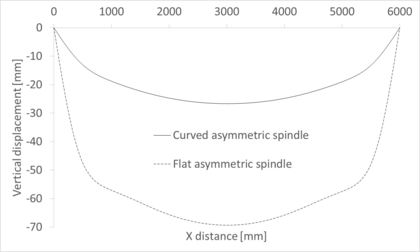
|
| Figure 53: Asymmetric double-tubed beams. Vertical displacement in the cables after loading |
The comparison between the different spindle shapes lets us extract some conclusions regarding the optimal design of the footbridge, from a structural point of view only. In terms of displacement and stresses, the curved asymmetric spindle is the best choice. Its only weak point is the higher level of tension in the cable at midspan, but this is never the most solicited point of the cable, so other points are of greater concern than this one.
The flat spindle shows properties opposite to the curved one. From a structural point of view, this is the least desirable option, since both displacements and stresses are larger than in the other two geometries studied. For example, the displacements in the walkway are almost three times larger than in the curved spindle and close to twice the displacement in the symmetric one, if maximum vertical displacements are compared.
The symmetric spindle is an intermediate option. Stresses in the cable and walkway are contained, while the maximum displacement is just one centimetre larger than in the curved spindle.
All these conclusions are summarised in Table 4.
| Geometry | Max. displ. | Max. cable ten. | Max. walk. compres. | Max. walk. ten. |
| [cm] | [MPa] | [MPa] | [MPa] | |
| Symmetric | 3.58. | 459.9 | 43.65 | 25.06 |
| Flat | 6.93 | 518.3 | 34.89 | 73.72 |
| asymmetric | ||||
| Curved | 2.67 | 417.8 | 51.12 | 10.01 |
| asymmetric |
4. Design of the footbridge
The theoretical background given in chap:chapter2 and the quantitative guidance of chap:chapter3 give an insight on the behaviour of the different design choices for a Tensairity beam. However, the decision of which beam is more appropriate for building a footbridge needs to take into consideration practical aspects as well, and not only structural ones.
Cylindrical beams can be discarded as a suitable option since they are not efficient when bearing bending loads and so they represent a waste of resources. The decision is then between asymmetric and symmetric spindles. A list of advantages and disadvantages for asymmetric spindles has already been discussed in [8] and is summarised in the following.
First, let us consider a curved asymmetric spindle, with parabolic or circular strut and a straight tensional member. The supports of this beam are aligned with the cable, while the centre of gravity lies above it. As a consequence, the beam tends to rotate along the axis of the supports when lateral loads are acting. On the other hand, the whole span under the footbridge remains clear, allowing its use without the need of any rising support, and the compression element remains curve, resisting bending efficiently. The straight cables are the most solicited elements of the beam.
If, on the contrary, the compression element is kept straight and the tensional one curved, the centre of gravity of the structure will fall under the axis of the supports, which coincides with the compression element. The structure is stable against lateral loads in this case. Besides, the increase of curvature in the tensional member reduces the tension it has to bear to equilibrate the external loads, with parity of displacements. The compression element, on the other hand, has a less efficient shape to hold bending moments, although this shape is much easier to build. Another disadvantage of this scheme is that the whole depth of the beam develops under the supports, so a trestle or other similar support would be needed.
The symmetric spindle, not discussed in [8], gives the possibility of curving both the compression and the tensional element. By doing so, both parts bear the external loads efficiently, in exchange of greater displacements than in the curved asymmetric spindle. The stability of the beam in this configuration depends on the radius of each element at midspan and the material used for each element. If the same material is used for the upper and lower parts and the latter has a larger radius, the centre of gravity of the beam falls under the axis of the supports and the structure will be stable.
Another advantage of using the same material for both elements is that the structure can withstand downward and upward forces. This may be important when considering suction forces, even though they are an order of magnitude lower than the usual inner pressure of the beam and therefore they are not relevant for the design of the footbridge [23].
Symmetric spindle bridges need to be elevated off the ground with trestles, too. However, only half the depth of the beam remains under the supports, so little clear space is needed to avoid contact with the ground. A slender design of the beam can avoid steep ascends to reach the walkway.
4.1 Final configuration and materials selection
This project aimed to design and build a prototype of inflatable and modular footbridge. The previous chapters served to ascertain the consequences of the different design choices in the performance of the final footbridge. Despite all this, the actual design has been influenced by other factors apart from the notions gained previously.
The main limitation was budget. This was important for the execution of the prototype, since we tried to reuse as many parts from previous projects as possible. Obviously, the project and its design decisions were heavily conditioned by this new constraint. In particular, there were a hull with a symmetric spindle shape, bolts and screws and several fabric belts that were used for a previous project [8]. The main design choices to make were then the walkway, the technology to allow a stiff modular design and the supports.
Regarding the walkway, and as there were belts available to couple it with the beam, the decision was to use directly a shell-like element to create it. That way, only one part served to bear the loads and as support for the passers above. As a result, the final design had to be a mix of the preliminary studies seen so far: only one tube but withstanding the load of a whole plane - not linear - compression element.
The length of the walkway when it is planar and prior to any deformation is of four metres. This was also imposed by the size of the hull and of the belts, which could not be stretched any further. The whole length is reached with four modules, each spanning one metre and half a metre wide. The extremes of such modules, when put together, fall on the central axis of the hull.
The material for the walkway had to be light, resistant to bending and economic. After a search in different commercial catalogues, the final decision was to use a sandwich panel. Due to the expected loads, consisting only on pedestrians walking above, a thin panel was chosen. It consists of three layers: two aluminium skins of 0.6 mm each and a central core made of rigid polystyrene foam, with a thickness of 8.8 mm.
This material offers a resistance of 200 to 300 kPa at 10% deformation. Besides, it has a low water absorption ratio, with a weight increase of less than a 0.5% after 28 days of total immersion. This makes it suitable for its use in waterlogged areas. Finally, it has a low density: only 30 .
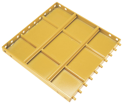
|
| Figure 54: Formwork panel |
This material was chosen after an extensive search of possibilities in the market. Other panels considered but later discarded were, for example, plastic formwork panels with built-in unions, like the ones shown in 54. This option was discarded because of the presumed weakness of the unions. Another option considered was carbon fibre wires, that should be joined to a platform that would serve as a walkway. This was discarded because of its cost, which would be probably too high to be a good commercial product.
Other possible choices could have been wood composite panels like the ones in Figure 55. These had the advantage of the nice aesthetics, but they were too thick and they presented problems with their size, which would require cuts that would make the slats asymmetric, and so additional embellishers would be needed. Perforated aluminium plates were also considered, but they were rejected due to the high density of the material.
One last option was using façade panels. Some of these panels have built-in unions that would allow a correct transmission of stresses. They were also light and their appearance could be customised, even to give a correct texture for the walkway. However, they were discarded due to their excessive thickness, in most cases above 5 cm, and because of their low resistance to loads. Façade panels are thought for thermal and acoustic isolation, they do not perform well under external bending loads.
|
| Figure 55: Wood composite panels |
The belts are made of high tenacity polyesthylene. Eighteen belts were available: two with an approximate length of four metres and others, always shorter but with different size, that serve to surround the hull and connect it to the walkway. The long ones are used as tensional elements of the Tensairity beam. A 3D sketch of the positioning of the belts with respect to the walkway and hull can be seen in Figure 56.
|
| Figure 56: 3D sketch of the prototype |
As seen there, the longitudinal belts do not join the walkway at the extremes of the footbridge. Instead, they curve before that and reach the modules almost 15 cm before that. These points are the ones with greater risk of failure of the walkway and the belts. The supports need to be as close to these union points as possible to avoid the appearance of eccentric forces and so additional bending moments. As a result, the supports lie above the central axis now, gaining stability for the beam.
|
| Figure 57: Double-T profiles between modules |
The hull, built from the same material as the already explained in chap:chapter3, has a profile that resembles a symmetric spindle. However, the shape of the cross-sections is not circular as seen so far. Instead, the belts and walkway prevent an equal expansion of the hull during inflation and so the cross-section appears straight in the vicinities of those other structural elements. This can be seen in the blueprint of the footbridge in Figure 58.
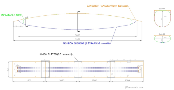 ] ]
|
| Figure 58: Blueprints of the prototype. Based on [8] |
The contacts between modules needed to provide a way to ensure the transmission of shear forces through the walkway, avoiding relative displacements between parts. The final design of the unions contemplates a double-T profile composed of two plates forming its extremes and a hollow square tube as the central part. The tube has the same height as the sandwich panel, one centimetre, while the hole has eight millimetres. A simplified sketch of these unions is shown in Figure 57.
The plates are only half a millimetre thick. In that way, the joins are flexible when the beam is deflated to allow an easy transportation and manipulation of the extended walkway. Then, the plates need to be screwed to both the panels and the tube in order to allow the transmission of stresses. The hollow and square shape of the tube is chosen based on a research on portable modular footbridges [24], in which the rectangular hollow aluminium tube provided the best results in terms of economy and weight, without an important decrease of the performance compared to steel and titanium.
Screwing is not a fast operation in the assembly of the footbridge. It actually slows down the process, but this decision was taken in order to use as many parts from previous projects as possible. More complex union technologies are left as a future development of this work.
4.2 Computational modelling
The proposed design brings new structural elements into the composition of the footbridge compared to the preliminary models. The main ones are the presence of the unions between modules, which break the continuity of the walkway, and the belts. These are modelled as membranes, and so they have no initial resistance against out-of-plane loads. This lack of resistance is specially important in the transversal belts, as they must contain the membrane during inflation. This, together with the particular cross-section of the airbeam, make it more difficult to reach a solution in the computational model. These problems were solved with the membrane stiffening property of the nonlinear analysis and with a small increment of the load at each step. Moreover, and in contrast to the previous cases, a static analysis will not converge and a quasi-static one is required.
Regarding the shape of the membrane, it is important to note that the blueprints of Figure 58 show the final expected geometry of the prototype. This should be reproduced as similarly in the computational model as possible. However, due to the impossibility of extruding the surface in AutoCAD with the given cross-sections of the airbeam, its final geometry was approximated by that given by a circular cross-section at midspan and ellipses at the extremes. The deformation during inflation, with the resistance provided by the belts, changes this shape to approximate the final geometry better.
Another particularity of the modelling of this footbridge with respect to the other ones is that the union between the walkway and the loading belts is not rotationally stiff. In other words, the rotational degrees of freedom in both elements at the union are not coupled. This is done to adjust better to the real condition in the footbridge that, as we will see later, does not have any structural element to ensure equality of rotations there.
In addition, the unions are not perfect transmitters of stresses and, in fact, the behaviour of the walkway changes as the beam inflates. Therefore, the appropriate modelling of these unions should be an intermediate between a hinge and exact continuity. An elastic joint seems the most logical choice, but the characterization of its stiffness would require additional information, which in addition would change according to the overpressure at inflation.
The necessary extra information was not available, and so a simpler approach was taken. The only certainty in the behaviour of the footbridge, regardless the pressure, is that it is bounded by the two extreme situations: the hinge and the continuous model. Consequently, both situations will be studied and we will be able to bound the real state of the footbridge. The inclusion of elastic joints and the study of their pressure-dependent characteristics is left as a further development of this work, which requires experimental data.
In addition, two load cases will be studied: a uniformly distributed load, similar to the ones already performed before, and a concentrated load at midspan. This last case is a punctual force in the middle of the walkway and it represents a person crossing the footbridge at its most critical moment. The value of the distributed load is 200 , and the punctual one is 200 kg. Overpressure is 105 mbar, as recommended by the author of the original project it was built for [8].
| Section | Material | Thickness | E | ||
| [mm] | [MPa] | [] | |||
| Sandwich panel | Aluminium | 0.6 | 69000 | 0.3 | 2700 |
| Polystyrene foam | 8.8 | 30 | 0.32 | 550 | |
| Membrane | Fabric 1302 S2 | 1.2 | 1035 | 0.235 | 1320 |
| Belts | High tenacity polyethylene | 2 | 5000 | 0.3 | 1380 |
Material and section information is shown in Table 5. These values are also a source of uncertainty, since no characterization tests were performed on them and providers do not include mechanical properties in their catalogues. For the aluminium, the standard Young modulus of 69 GPa has been taken, but it could change depending on the alloy used in the sandwich panel. The same happens with the polystyrene foam. In this case, the characteristics of the material have been chosen by comparison with data extracted from bibliography [25,26,27]. The mechanical properties of the belts have also been estimated from bibliographical ones [28,29]. A lower value than the ones appearing there has been taken as it was assumed that the material used in the original project was not so advanced as the ones shown in these documents.
4.2.1 Distributed load
The first case of study will be a distributed load along the whole length and width of the deck. The same module of 200 is kept as in the preliminary examples as to compare their behaviours.
Regarding inflation, the most remarkable aspect is the influence of the transversal belts: now the central sections do not expand in every direction as they would with no restrictions. Instead, these sections go up completely. At the extremes of the beam the usual behaviour is recovered and the beam expands. This is shown in Figure 59, which displays the vertical component of the displacements. The effects of the belts are also noticed in the stresses, reducing tension in the contact zones close to the centre. This can be seen clearly in the minimum principal stresses of Figure 60. This process is analogous in the hinged and continuous footbridges and obviously for any load process that may happen after.

|
| Figure 59: Vertical displacement after inflation in the membrane |
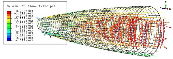
|
| Figure 60: Minimum principal stresses in the hull after inflation |
Once loaded, the behaviour of the membrane does not change much, similarly to what happened in the previous examples. Consequently, we will focus on the loaded state from now on. Unlike before, a study of both the top and bottom layers of the sandwich panels of the walkway is required. Tension in the membrane elements, on the other hand, is constant along their thickness. Let us take as an example the hinged footbridge. The top layer is subjected to the principal stresses of Figures 61 and 62. Meanwhile, on the bottom layer, the stresses are the ones shown in Figures 63 and 64.

|
| Figure 61: Hinged footbridge under distributed load. Maximum principal stresses on top of the deck |

|
| Figure 62: Hinged footbridge under distributed load. Minimum principal stresses on top of the deck |

|
| Figure 63: Hinged footbridge under distributed load. Maximum principal stresses at bottom of the deck |

|
| Figure 64: Hinged footbridge under distributed load. Minimum principal stresses at bottom of the deck |
From these plots, we can see that the stress state is fairly variable along the thickness of the deck. The largest stresses are concentrated in the vicinities of the extremes of the hull, except on top of the deck, where they concentrate at the same length but at the sides of it. Most of the bottom layer works in compression, while the top one does it in tension. This is the opposite of the bending effect that we would expect from the external load. In fact, this seemingly opposite direction of the bending moment is due to the inflation phase, which dominates the tensional state of the walkway.
It seems so that the most risky load state for the deck would be inflation, at least under reasonable loads. This is actually not true, as we will see in the next section of this work. It will be checked how the most critical point of the beam is the contact between walkway and loading belts. Figure 65 shows how the tension in the belts is maximum at the supports. Due to equilibrium of forces at that point, the walkway suffers an equivalent compression that may cause local failure.

|
| Figure 65: Hinged footbridge under distributed load. Tension at the belts after loading |
In any case, it is clear from these previous plots that the bottom layer is more suitable for failure than the top one, as it has larger compression and tension stresses. This statement applies to both the hinged and the continuous footbridges, and so we will compare only this layer to see the most unfortunate case. The stress state of the deck for the continuous footbridge is depicted in Figures 66 and 67. Comparing these with the hinged case, we see that there is little difference in the geometrical distribution of the stresses. In both cases the greatest compressions appear at about one and three quarters of the length of the beam, while the greatest tensions are next to the extremes of the airbeam. The central part of the deck does not suffer from great stresses. Nonetheless, there is a difference in the values of those stresses, which maxima are always higher in the continuous than in the hinged footbridge. The largest tension has a 23.87% increment in the continuous with respect to the hinged deck, while the largest compression has a difference of 12.22% with respect to the hinged footbridge.

|
| Figure 66: Continuous footbridge under distributed load. Maximum principal stresses at bottom of the deck |

|
| Figure 67: Continuous footbridge under distributed load. Minimum principal stresses at bottom of the deck |
We can conclude then that, in terms of stresses, a less stiff footbridge would be preferable over a completely continuous one. Regarding displacements, as seen in Figure 68 for the central line of the walkway, both cases are very similar. Surprisingly, the hinged footbridge has smaller displacements than the continuous one, so this option would be preferable for this, too. This comparison does not stand when checking the vertical displacements of the loading belts. In this case, the hinged beam has a worse behaviour as it moves 1.56 cm downwards versus the 1.21 cm of the continuous case. More clear space would be needed under the footbridge if contact with the surface below is to be avoided.
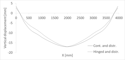
|
| Figure 68: Footbridge under distributed load. Vertical displacements along the deck |
4.2.2 Point load
The second case is that of a vertical load acting on top of the central point of the walkway, with a value of 200 kp. This corresponds to a high load on the worst point of the structure, the worst case scenario of serviceability of the footbridge.
Again, two computational models have been developed to bound the tensional state and the displacement fields of the beam. We will follow the same order as before, exploring the stresses of the deck after loading. Unlike before, the stresses at the top and bottom layers are similar now, still with larger values at the bottom. Now, the maximum stresses are found under the loading point, be it in tension and compression. Concentrations of smaller stresses appear above and on the extremes of the membrane, but they lose relevance due to the high stresses at the middle. This is shown in Figures 69 and 70 only for the bottom layer of the deck.

|
| Figure 69: Hinged footbridge under concentrated load. Maximum principal stresses at the bottom of the deck |

|
| Figure 70: Hinged footbridge under concentrated load. Minimum principal stresses at the bottom of the deck |
Tensional stresses are larger in the continuous walkway than in the hinged one: a 42.20% increment in the largest tension. However, the largest compression appears at the hinged walkway this time, with an increment of a 178% with respect to the continuous case. This large difference is explained because of the absence of large compressive stresses under the loading point in the continuous deck, while there are two very compressed elements in the hinged deck. The principal stress distribution for the bottom layer of the deck in the continuous case is shown in Figures 71 and 72.

|
| Figure 71: Continuous footbridge under concentrated load. Maximum principal stresses at the bottom of the deck |

|
| Figure 72: Continuous footbridge under concentrated load. Minimum principal stresses at the bottom of the deck |
The appearance of such large stress values should be treated carefully, especially if such a large difference is found. If these heavily loaded mesh elements are ignored, the stress state is much more similar in both geometries.
Regarding displacements, this time it is satisfied that the hinged airbeam deforms much more than the continuous one. The displacement field is similar in shape in both situations, with the central cross-section moving downwards, creating a shape similar to a triangle with the supports, as displayed in Figure 73
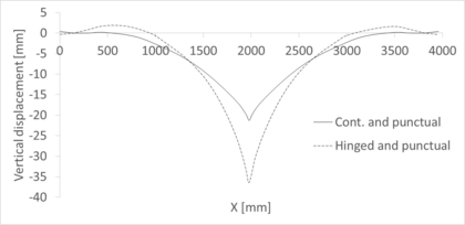
|
| Figure 73: Footbridge under concentrated load. Vertical displacements along the deck |
The vertical displacements in the belts are much lower now than in the previous case, with almost no final displacement of the belts with respect to their initial position. In the hinged case, the central point of the belts would go downwards 184 mm, and 5.24 mm in the continuous beam.
4.3 Construction of a prototype
The footbridge described in sec:final_configuration has been built in the laboratory of the Civil Engineering department of the UPC, at Campus Nord, Barcelona. The purpose of building it was to try the suitability of the sandwich panel as material of the deck and the performance of the designed unions. All pictures related to this section are shown in the second appendix of this work in order to ease its reading.
The four modules were cut by the providers in pieces of 1x0.5 m, and the aluminium plates were bought with the desired measure of 50x25 cm. The hollow square tubes, which needed to be 50 cm long, had to be cut in the laboratory from 1 m long pieces. Then, all these elements were drilled and screwed to create the continuous walkway. Figures from 77 to 80 show the disposition of the drilled holes in both the panels and the plates. They should be joined in a symmetric fashion with respect to the centre of the beam, in such a way that the elongated drills are placed at the extremes of it. These last drills serve to pass the loading belts and connect them to the deck.
The transversal belts are joined to the panels through bolts, as seen in Figure 81. On the contrary, the loading belts are coupled to the deck through shackles, thus the uncoupled rotational degrees of freedom in the computational models.
For the supports, hard paperboard cylinders were placed under the coupling points between loading belts and walkway. These belts, when tensioned, avoided the movement of the cylinders towards the interior of the beam. A piece of wood was placed behind one of the cylinders to avoid also its movement towards the exterior of the beam. The other cylinder was left loose to better approximate the supports of the computational models. The blocked support can be seen in Figure 82.
The set up of the beam took several hours once all the pieces were drilled. Note that all the assembly was done by a single person without the need of any special equipment but a screw-driver and a wrench. In addition, the drills were performed with means that allowed little precision and so extra efforts were needed to make all the pieces fit. A more systematic and automatised work on the modules would allow a faster assembly. All the same, alternative stiffeners for the unions would make a good improvement in the speed of the assembly, which is left as a future development of this work.
Sensors to measure displacements, stresses or deformations were not available at the time in which the prototype was built. Consequently, a traditional loading test could not be performed. Instead, the footbridge was tested as it would perform in service conditions; that is, the behaviour of the beam was tested when a person with average weight walked along the deck.
We see that the beam behaves as a stiff body, with displacements inside an acceptable range and no sense of insecurity arising from the vertical displacement. However, the beam suffers from torsion if the passer does not walk in the central part. The effect of torsion was magnified by the fact that the membrane, after inflation, does not fit symmetrically under the walkway. There is no apparent reason for this, so we assumed that the hull has suffered some damage during its previous uses or stock and so it does not inflate equally in all directions, leading to an incorrect position once the belts are tight. The effects of a person placed not on the middle but on an edge of the beam are shown in Figure 86. As seen there, the beam is far for overturning and so this problem could be solved, at least in terms of sense of security, with a handrail attached to the walkway. For the sake of clarity, the bright part of the walkway near the extreme at Figure 86 shows a strip of American tape that fixes the piece of wood to the walkway for the support; it is not a sign of failure in the footbridge.
Another problem detected after loading is that the panels suffered local plastic deformations in the contact with the loading belts. This is shown in Figure 87 for one of the sides. Similar effects were observed in the other one.
This concentration of stresses was predicted in the computational models; it was one of the objectives of this prototype to test the behaviour of the sandwich panels against these loads. Once the test was performed, additional aluminium plates were placed on those positions to avoid further damage to the footbridge. The reinforced contacts are shown in Figure 88.
5. Economic analysis
5.1 Competition analysis
A brief overview of possible competitors in the temporary and deployable bridges market is already given in chap:chapter1. However, the list presented there had the purpose of describing their technologies and seeing their limitations. Now, a more economical and business-oriented point of view is required.
Many of the bridges presented before, even if they are deployable and projected for temporary uses, do not compete directly with the solution presented here. This footbridge is thought mainly for emergency uses and for pedestrians. Thus, it does not compete with any bridge that links roads during maintenance or repair operations of the permanent one or any other bridge that carries heavy vehicles.
Out of the ones presented in chap:chapter1, the bridges that could compete with the modular footbridge are:
- Bailey bridge
- Pedestrian footbridge by Acrow
- Infantry Assault Bridge by General Dynamics
Bailey bridges are thought both for temporary and permanent uses, and they can carry heavy vehicles if double-storey bridges are used. These dualities imply that the material, mainly steel, is heavier than those of any other option. Deployment, even though it does not require heavy tools, takes several hours or even days when long spans are required, and it needs crews of more than one person to do the job. On the other hand, its strong points are the high load carrying capacity and the modular structure, which allows up to 61 meters to be deployed.
This bridge is then not likely to compete directly for costumers seeking emergency bridges, but it could be a competitor for other uses, such as a temporary bridge to cross zones that are waterlogged during long periods.
Acrow's bridges are similar to Bailey ones. They are thought for temporary, but prolonged in time, uses, such as in excavation and drilling sites or traffic detours, as indicated in their website. All the same, its modular structure allows also constructing smaller versions of this bridge, fitted for pedestrian use. The advantages and disadvantages of Acrow's bridges are the same as for the Bailey bridges, and so they do not compete in the emergencies sector either.
On the other hand, the Infantry Assault Bridge (IAB) by General Dynamics is lighter and easier to deploy than the other choices. This bridge is made of aluminium instead of steel and is assembled without the need of special equipment. The IAB modules can be carried by hand, but if a whole set wants to be deployed, which builds up to 30 meters, a light truck is needed.
The total span of 30 meters is achieved with seven modules, which can be set up in several minutes, depending on the size of the crew 1. This fact, together with its lightness, are the main advantages of this design.
The IAB is designed for military use. In this field, it has proven to work well even under combat conditions. The Tensairity footbridge presented here is not adequate for this, as the hull is sensible to puncture and stabbing loads. Besides, the IAB could perform well also in rescue operations due to its quick assembly and lightness. Therefore, the IAB is a direct competitor of our proposal.
After a more extensive research, some other alternatives of rescue bridges have been found. These are the PVC Inflatable Bridge by Azart [30], Convertex Rescue Bridge [31] and PKI's Rescue Bridge [32].
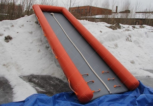 ] ]
|
| Figure 74: Azart`s Rescue Bridge. Extracted from its official website [30] |
Azart's and Convertex's designs are conceptually similar. They are both relatively wide and with the same scheme as a catamaran; that is, inflated tubes in the sides joined by a membrane in the middle. They are thought to be used on a continuous support, especially designed to cross un-walkable surfaces such as water or ice. Due to this, they can bear many people at the same time. For example, the smallest Convertex bridge can withstand the load of twelve people at once. However, the load carrying capacity is expected to fall if the structure is not continuously supported, as its walkway is but a thin inflated membrane. In spite of their names, we can practically consider these designs as rescue platforms and not bridges.
These structures are completely inflatable, requiring a low overpressure in order to perform correctly. In any model, the design overpressure is lower or equal to 500 mbar. This makes them easy and fast to deploy and inflate. However, it also makes them weak to stabbing and point loads as, opposite to the Tensairity system, the hull is not covered with any hard material. Besides, the load carrying capacity of these structures reduces drastically when they are simply supported, acting like an airbeam. Large displacements and low load resistance should be expected if they were used to cross a void space.
Consequently, these bridges have a limited range of application, serving more as a stabilizer element on un-walkable surfaces more than as a proper bridge. They could be used in overseas rescue operations and as temporary paths in waterlogged spaces. Nevertheless, even in this last application, they are not suitable for handicapped people, as at least one of the extremes is an inflated membrane, too high to cross with a wheelchair (Figure 74). Table 6 shows a comparison of the different models by Azart and Convertex available in the market.
PKI's alternative is similar to the last two but presents two major differences. First, the structure is not made solely of a hull but it uses wood segments in the transversal direction to stiffen the walkway. Furthermore, it is inflated to a relatively high pressure, 1.2 bar, delaying its deployment.
This design offers a longer walkway than the two previous models and a high load carrying capacity; up to 200 , due to the high pressure and wood reinforcement. This resistance is achieved, like before, when the whole bridge lies continuously supported on a surface such as water.
In practice, the range of uses of these three bridge models is the same, being especially useful for covering distances in flooded areas.
Some other bridge models for temporary uses are produced by companies like Bridge It NZ, Groundforce and Matrax. These are large companies that produce different footbridges than the inflatable ones presented before. These are much heavier and resistant, but in exchange they do not need a continuous support to bear loads.
Bridge It NZ offers a steel bridge with wooden deck. In their website, they offer temporary bridges of any length and 2.4 m width. The design of the bridge adapts to the project, and so a wide range of options are available. It is safe to assume that this fact delays and makes the deployment more expensive than a modular prefabricated footbridge.
Matrax's cheapest -and weakest- portable bridge design is made of dense wood mats and steel rods, as seen in Figure 75. The savings in materials must be paid in transportation, assembly and deployment costs. The load carrying capacity of this bridge allows the passing of heavy machinery, and it is available in spans lower or equal to 16 feet.
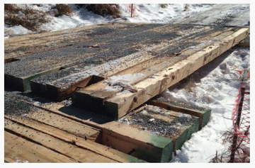
|
| Figure 75: Matrax's simplest portable bridge. Extracted from their website |
Groundforce's option is somewhat different from the other ones as it is a completely metallic bridge, though only for pedestrian use. This is a non-engineered solution, with a closed design measuring 8 m long and 1.6 m wide. It is fast to install, it can be done in less than one hour by a crew of two people, and is designed to allow the pass of disabled people. In addition, the bottom part of the bridge is flat, so no clear space is needed under the bridge.
These companies are already settled and have relatively large sizes and experience. For example, Matrax operates in a large territory in the US, which includes states such as Maryland, Pennsylvania, New Jersey, Florida, Ohio and Indiana. Bridge It NZ is smaller, operating only in New Zealand, but still has 11 to 50 employees, as stated in their Linkedin profile. Groundforce is much larger, with 1000 to 5000 employees. Its homeland is the United Kingdom.
(1) http://www.army-technology.com/products/infantry-assault-bridge
5.2 Product diversity
The design proposed in this work differs from any other portable and/or temporary bridge and footbridge in the market. Its main advantages are:
- Lightness. The whole bridge can be grabbed by a single person. This increases the easiness to transport and deploy it.
- Fastness of deployment. The current design requires screwing eighty screws and bolts to fix the modules. However, the set can be transported in a way that all transversal belts are already fixed and the double-T profiles of the joints are screwed to one of the modules. In that way, only twenty four screws should be placed on site. This is a fast operation that requires nothing but a screw-driver and a wrench.
- High live/dead load ratio. As an example, the prototype, weighting less than twenty kilograms, could bear the weight of an average build man; that is, between seventy and eighty kilograms.
| Bridge | Length | Width | Pressure | Mass | Pack. volume | Max. load | Inflation time |
| model | [m] | [m] | [mbar] | [kg] | [m] | [people] | [s] |
| Azart | 3 | 1.47 | 500 | 16.5 | 0.75x0.5x0.3 | - | - |
| NM-A3 | |||||||
| Azart | 5 | 1.47 | 500 | 27 | 0.75x0.65x0.4 | - | - |
| NM-A5 | |||||||
| Azart | 10 | 1.47 | 500 | 55 | 0.85x0.75x0.6 | - | - |
| NM-A10 | |||||||
| Convertex | 6 | 1.5 | 210 | 26 | 1.4x0.25 | 12 | 25 |
| 6m | |||||||
| Convertex | 10 | 1.5 | 210 | 35 | 1.4x0.35 | 18 | 35 |
| 10m | |||||||
| Convertex | 12 | 1.5 | 210 | 44 | 1.4x0.45 | 24 | 45 |
| 12m |
The main property of the Tensairity scheme is the innovative synergy between stiff and inflatable materials, which prevents buckling from happening if a large enough pressure is reached. Materials can be then fully exploited up to their yielding limit, which in turn means that the material needed to bear a certain load is less than in traditional structures. In practice, this means that the deck is thinner than in the other presented footbridges. In our design, one centimetre thick sandwich panels were used. One extra millimetre was placed as reinforcement of the deck-loading belts joints. The full deck can be then stacked in a 4.4 cm high pile, with width 0.5 m and length 1 m.
The hull can be rolled by hand into a cylinder with height half a metre and diameter smaller than that. This was checked by myself when transporting the materials to the laboratory at Campus Nord. Each union between modules is just 1.1 cm high, 50 cm wide and 25 cm long. The belts and screws are really small and can be placed in any bag or small compartment. The whole package can be carried by a small crew or on any vehicle larger than a motorbike.
Another advantage of the proposed design is its price: the reduction of needed material and the standard design, not dependant of the location of the area to surpass, cheapen the production cost of the footbridge. Additional cost-effectiveness is gained from the lack of heavy equipment or special tools needed to assemble the footbridge.
Additional improvements to this design, such as fireproof materials or a more reinforced deck which avoided any plastic deformation would further increase the benefits of this option against its competitors. Moreover, it seems that, as the length of its competitors indicate, a longer bridge could be more helpful for emergency tasks. The optimal length should take into account the increase of weight that accompanies it. Comparing with the models presented in the previous section, a length of 7 m is deemed as a more appropriate choice rather than the current 4.
5.3 Potential clients
As already mentioned along this work, this footbridge is thought for military -out of combat- and emergency uses. The main potential clients would then be armies and civil protection corps, such as firefighters or police.
The emergency forces of Spain have experienced an increased of budget to improve and renew their equipment since these past years. Budget items depend on the autonomic government, but it is a generalised trend since the year 2015, as proven by the 5% increase of the budget for acquisition of new vehicles and rescue tools by the Canary Islands firefighters 1.
In 2016, the Valencian government invested 4300000 € in new equipment for the firefighters, what meant an increase of 3 million euros with respect to the previous year 2. The same trend can be seen in other communities, such as Asturias 3, and in 2017 in cities like Málaga, where the budget destined to the firefighters department increased a 12% with respect to 2016 4. In this case, Civil Protection also saw a budget increase of 116250 € to buy new equipment and for maintenance. Another example can be found in Cantabria, which bought new material for emergency interventions for a value of 700000 € 5.
Another factor that favours the spreading of this product is the ever increasing amount of floods in urban areas. Unfortunately, global warming concentrates episodes of heavy rain [33]. At the same time, many countries in the world keep experiencing a rapid urban growth, especially the developing ones [34], which is in many cases accompanied by deficient drainage systems. Developed countries have already stabilised their growth and have quality drainage systems, but all the same the drainage capability of the soil has been reduced due to the setting of impervious concrete layers on the ground.
These factors provoke that, in the end, both developed [35] and developing [36] countries are exposed to greater risks of flooding. A solution such as the proposed footbridge is then a convenient tool to allow pedestrian mobility inside these areas. Its main advantages in this situation are its versatility to adapt to different water levels by simply elevating the supports, and its cost, which is detailed next.
(1) [www.bomberostenerife.com/ct/general/el-consorcio-de-bomberos-incrementa-en-un-5-su-presupuesto-para-el-2016/ Source: www.bomberostenerife.com]
(5) Source: www.europapress.es
5.4 Cost-benefit analysis and sales estimation
Regarding costs, it is possible to estimate a unitary cost for the footbridge. For this prototype, a total of 53 € were spent for the sandwich panels, while the aluminium joints together with the screws and the reinforcement for the extreme points cost 80 €. The rest of the elements were reused from a previous project. The price of the membrane plus its sewing and needlework is estimated to be around 20 €/ -asked directly to a salesman working for Buildair's provider-. The price of the belts is estimated to be 15 €/m from a comparison of similar products to the one used in the prototype. The total area of the membrane is approximately 4.63 , and that of the walkway is 2 . On the other hand, the total length of the belts is 17.71 m. Therefore, the estimated total price of the prototype is 491.25 €. Rounding up, we could approximate that as 500 € for the whole structure. This is equivalent to 250 €/ of walkway, or alternatively 125 €/m of footbridge.
An estimation of the retail price for the final product is 2000 € plus the correspondent value-added tax. This price is composed of two parts: one due to the labour of production and another one due to the distribution. Indeed, the potential market for this product is worldwide and thus distribution should be assigned to a different company. A reasonable share of 70%% for each part is considered, respectively. This makes the gross margin (GM) for our part equal to 1400 €. The expected benefit from each unit sold can be then extracted by decomposing this gross margin, as done in Table 7.
Five items are considered in the decomposition. The first one is the direct cost of the materials. This value has already been estimated in absolute value from the construction of the prototype. The second item represents the costs from labour, infrastructure and taxes derived from the company producing and selling the footbridge. This item includes handwork directly connected to building the product, but also administrative work and new taxes that would not exist if the footbridge were not produced. The third item is a payment to the owner of the Tensairity patent for its commercial use [8]. Finally, another component of the GM is reserved for further research and development of the product. A relatively high value of 10% is considered as this is only a concept test of the footbridge and many improvements have to be included for a commercial design. Profit per unit sold is then estimated as the remaining GM not used for the other items. A final value of 200 € is obtained.
| Item | % over GM | € |
| Material cost | 36 | 500 |
| Labour and other business related costs | 30 | 420 |
| Royalties | 10 | 140 |
| R+D | 10 | 140 |
| Profit | 14 | 200 |
As mentioned above, the potential market for this product is worldwide. The main sector of this market is that of emergency services. Other possible sectors, such as temporary works or repair interventions, are considered secondary and they will not be taken into account in the estimation of sales.
Only in the first semester of 2017, 80.6 million people were affected by a natural disaster. Out of these, a 26%, i.e. 20.956 million people, were victims of floods [37]. Hypothesizing similar statistics for the second semester of the year, 41.912 million people could use a product similar to this one in 2017. This potential demand is kept constant for every successive year.
| Continent | GDP [ €] | Market share [%] | Potential annual sales [] |
| Europe | 19070 | 26.55 | 12689 |
| Latin America | 5429.451 | 7.56 | 3613 |
| North America | 20098.32 | 27.98 | 13374 |
| Asia | 27222 | 37.9 | 18114 |
| Total | 71819.78 | 100 | 47790 |
| Market share | 0.5% | 1% | 2% | 3% | 5% |
| Continent | Year 1 | Year 2 | Year 3 | Year 4 | Year 5 |
| Europe | 63 | 127 | 254 | 381 | 634 |
| Latin America | - | 18 | 36 | 72 | 108 |
| North America | - | - | 67 | 134 | 267 |
| Asia | - | - | - | 91 | 181 |
| Total | 63 | 145 | 357 | 678 | 1190 |
It is considered that, after a flood episode, an acceptable time of evacuation for the population is half an hour. Considering a capacity of two passengers per minute for a walkway, then we would need a footbridge for every 60 people affected by floods. However, this number is not realistic, since it considers that everyone would indeed need immediate evacuation after a flood, and also that a 4 m footbridge would be enough to evacuate them. Indeed, only the 0.0068% of people affected by floods died during the period 1995-2015 [38]. Clearly, such a low value is most likely due to the effort of emergency and rescue services. For example, the Fire Brigade of the UK attended 1095 incidents during a flood event in Cumbria in December 2015 [39]. During that same event, 16000 homes were flooded 1. Roughly, we can say that a 7% of the houses needed assistance. Therefore, applying this same proportion to the total number of people affected by floods, we obtain that we would need a footbridge for every 877 people affected by floods.
Potential customers are public organizations but also NGOs and any other organization devoted to humanitarian help. Consequently, the geographical distribution of the buyers does not necessarily match the distribution of natural disasters. Instead, demand will be studied through the economic power of each zone. Here, it will be considered that we cannot supply to the whole world at once but instead we expand to a new continent each year. This delay is due to the work needed to negotiate with new distributors and to contact new customers. The first year, product supply will be limited to Europe. Subsequently, supply will expand to Latin America, North America and Asia, in that order. Supply to Africa and Oceania arrives from exports external to our commercial activity.
The size of the market in each continent is determined through the comparison of their gross domestic product (GDP) in 2016, which is readily available on the web. Table 8 summarises the division of the annual potential market, which is considered constant for the first five years after the start of commercialization.
Of course, that represents the total market in each area. The market share in each area of our product depends on time, expecting it to grow over the years. The inflatable footbridge competes with other footbridges made with traditional materials and also with other technological solutions, such as plates and even ladders. Market penetration rates have already been estimated for a similar market -in terms of inflatable over traditional structures- in [8]. They are shown in the first row of Table 9, while the rest of the table shows the estimated amount of footbridges sold each year. There, each new market starts with the penetration rate of the first year, even if the first units are sold in successive ones.
Finally, the amount of units sold and the price apportionment allow to estimate the gross margin and benefit for the company in each year. The results are shown in Table 10.
| Year 1 | Year 2 | Year 3 | Year 4 | Year 5 | Total | |
| Total sales [u] | 63 | 145 | 357 | 678 | 1190 | 2433 |
| Gross margin [€] | 88200 | 203000 | 499800 | 949200 | 1666000 | 3406200 |
| Benefit [€] | 12600 | 29000 | 71400 | 135600 | 238000 | 486600 |
(1) http://www.bbc.co.uk/news/uk-35235502
Conclusion
This project had the objective of designing an inflatable and portable footbridge. Tensairity has been proven as a valid and attractive technology to reach this objective, showing some good characteristics in terms of weight, lightness, load capacity against self weight ratio and simplicity in the assembly due to the low amount of structural elements and low internal pressure. The main concept behind this technology is that the necessary amount of material to withstand an external load is reduced due to the impeded buckling. To ensure buckling does not happen, it is enough to inflate the beam to a pressure dependent on the load.
Prior to the design stage of the project, simpler structures have been studied. The focus was laid on simple isostatic beams. The main features of those beams -cylindrical, symmetric and asymmetric spindles- have been presented. The theoretical background shows that the cylindrical beam can be disregarded for its lack of efficiency is carrying stresses and due to local buckling problems at the extremes. Spindles solve the local buckling problem and also improve the performance of the beam. In this sense, asymmetric spindles with curved compression element are the stiffest, suffering from the least displacements under the same load as symmetric or flat asymmetric spindles, in exchange of larger stresses per unit displacement in the tensional element. Flat asymmetric spindles invert this, presenting larger displacements but lower stiffness than its counterpart. Symmetric spindles show a compromise between these other two options.
Analytical models have been introduced for simple beams with spindle schemes, circular cross-section and linear compression and tension elements. Two benchmark problems were computed through these models, one a symmetric spindle and the other one a flat asymmetric spindle. They have been used to check the accuracy of computational models which solution was computed through a Finite Element solver. The results show good accuracy of the computational models with respect to the analytical ones, which are considered the actual solution, especially for the symmetric spindle. In the asymmetric one, the general trend was well captured, but the magnitude of the displacements was underestimated, with a maximum error near 3 cm at midspan in the compression element.
More complex structures must be studied by means of computational tools. The main aspect of the modelling of Tensairity structures is non-linearity. The model developed here considers only geometric non-linearity, allowing large displacements and also a stress-induced increase of the stiffness of the membrane. Another important characteristic of the models is the assumption of quasi-static loading for both inflation and loading. This assumption allows to include dampening in the system while ignoring inertial effects. These two properties allow both a realistic representation of the phenomena and a relatively easy convergence in the solution.
A final design proposal for the pedestrian footbridge has been presented and studied, which stands out for its modular walkway. In fact, this work presents the first study on modular Tensairity beams that the author is aware of. This modular walkway, composed of sandwich panels, has been proven to be capable of working properly on serviceability conditions in both the computational model and in a tested prototype. Other advantages, such as the simplicity of the assembly, the lightness and the convenient design for transportation make it feasible to use this concept for commercial purposes. Technical improvements, such as the union between compression and tension elements or lateral stability are left for a commercial design of the product.
Finally, the market for this kind of product has been analysed. It has been found that this proposal stands out from its competitors for being the lightest and one of the simplest in terms of assembly. The inflatable footbridge is suitable for commercial production, for which further work in technical and business fields is required.
Future developments
The lines for future developments have already been settled by the potential clients consulted for the market study. Mainly, the current design could be improved with: a longer walkway, measuring 6 m, a double-tubed design for improved stability and faster assembly.
Regarding the last point, a possible way that could be investigated is using clip fasteners for both the transversal unions and the joints between elements. For example, accessories similar the one shown in Figure 76 could substitute bolts for the transversal belts. They could also be placed at the sides of the unions between modules, replacing or at least reducing the number of necessary screws. The clips shown in the Figure are commercially available and also very cheap, with a price depending on their width when open.
Another alternative worth exploring is getting rid of the transversal belts. With a double-tubed design, the walkway could be directly attached to both tubes. A wider walkway allows to limit a central passing zone that falls between the airbeams, so the loads are better distributed to the new lineal union zones along the walkway and membranes.
In addition, inflation time could be reduced by including a larger valve in the membranes. The one currently in place measures less than 1 cm in diameter and allows only little entry flows.
|
| Figure 76: Substitute for screws and bolts. Adapter from a commercial catalogue |
Another task to improve this work is to compare the computational results with laboratory tests. In the same way, materials should be tested to extract a more accurate characterization of their elastic properties and their failure modes, which would be useful to assess the reliability of the structure. Further tests could include a dynamic analysis of the structure and its behaviour to lateral loads, as well as buoyancy and lateral stability studies.
Finally, the prototype could be complemented with a handrail system, so that it can be tested more safely by anyone willing to try it, and some anti-slippery layer could be placed in the central part of the walkway, improving safety as well as defining a central pass zone, which reduces the eccentricity of the applied loads.
Appendix A. ODE8 models
A.1 ODE8 model for symmetric spindles
%%ODE8 model for single-tubed symmetric spindles.

%This script solves the analytical model for symmetric Tensairity
%spindles provided in the paper "Structural Behavior of Symmetric
%Spindle-Shaped Tensairity Girders", by Luchsinger, R.H. and Galliot, C.,
%2013.
%The beam must have a single hull and tensional and compression elements
%assimilable to beam or truss elements. Same material properties and
%sections are considered in the strut and the chord

%Preliminary operations
clear all;clc;close all
disp('ODE8 model executed')
syms x H C1 C2 C3 C4 C5

%% Input section
%Parameters of the model. International System units are used, but any
%coherent units choice is valid
E=1.6e11; %Young modulus of the strut and the chord
I=1/4*pi()*0.02^4; %Inertia of circular cross-section with R=2 cm
A=pi()*0.02^2; %Area of cross-section
f1=0.30; f2=f1; %Geometric parametre as defined in the original paper
p=10500; %Overpressure
l=3; %Length of half a beam
q=980.7; %Distributed linear load

%% Solver
%Preliminary calculations
k=pi()*p/2;
EI=E*I;
N=E*A;
H0=q*l^2/(2*(f1+f2)); %Initial guess of H
s1=l+(2*f1^2)/(3*l); s2=l+(2*f2^2)/(3*l);

%Critical loads
H_c=sqrt(2*k*EI);
Q_c=8/(2*l/(f1+f2))*sqrt(pi()*p*EI);
q_c=Q_c/(2*l);

%Defining the functions
L=((2*k*EI-H^2)/(4*EI^2))^(1/4); C3=-(H-H0)*(k*(f1+f2))/(48*EI^2*L^4*l^2);

w1=@(x) cosh(L.*x).*cos(L.*x)./L^4.*C1+sinh(L.*x).*sin(L.*x)./L^4.*C2+x.^4.*C3+x.^2.*C4+C5;
dw1=matlabFunction(diff(w1(x),x));
d2w1=matlabFunction(diff(dw1(C1,C2,C4,H,x),x));
d3w1=matlabFunction(diff(d2w1(C1,C2,C4,H,x),x));
d4w1=matlabFunction(diff(d3w1(C1,C2,H,x),x));
w2=matlabFunction(EI./k.*d4w1(C1,C2,H,x)+H./k.*d2w1(C1,C2,C4,H,x)+w1(x)-q/k+H*2*f1/(k*l^2));
dw2=matlabFunction(diff(w2(C1,C2,C4,C5,H,x),x));
d2w2=matlabFunction(diff(dw2(C1,C2,C4,H,x),x));

%Stating the system of equations
ec1=w1(l)==0;
ec2=w2(C1,C2,C4,C5,H,l)==0;
ec3=dw1(C1,C2,C4,H,l)-dw2(C1,C2,C4,H,l)==0;
ec4=d2w1(C1,C2,C4,H,l)+d2w2(C1,C2,C4,H,l)==0;

disp('Starting to solve the system for constants')

sol=solve([ec1,ec2,ec3,ec4],[C1,C2,C4,C5]);
C1=matlabFunction(sol.C1);C2=matlabFunction(sol.C2);C4=matlabFunction(sol.C4);C5=matlabFunction(sol.C5);
C3=matlabFunction(C3);L=matlabFunction(L);

disp('Constants found as function of H')

%Finding the horizontal force H
w1=@(x) cosh(L(H).*x).*cos(L(H).*x)./L(H)^4.*C1(H)+sinh(L(H).*x).*sin(L(H).*x)./L(H)^4.*C2(H)+x.^4.*C3(H)+x.^2.*C4(H)+C5(H);
dw1=matlabFunction(diff(w1(x),x));
d2w1=matlabFunction(diff(dw1(H,x),x));
d3w1=matlabFunction(diff(d2w1(H,x),x));
d4w1=matlabFunction(diff(d3w1(H,x),x));
w2=@(x) EI./k.*d4w1(H,x)+H./k.*d2w1(H,x)+w1(x)-q/k+H*2*f1/(k*l^2);

intw1=matlabFunction(int(w1(x),x,0,l));
intw2=matlabFunction(int(w2(x),x,0,l));
disp('Integrals computed as function of H')

%Plotting compatibility at the supports for values of H
lhs=@(H) H.*s2/N-2*f2/l^2.*intw2(H);
rhs=@(H) -H*s1/N+2*f1/l^2*intw1(H);
y1=zeros(1,200);
y2=zeros(1,200);
v1=linspace(0,2*H0,200);
for i=1:200
    y1(i)=lhs(v1(i));
    y2(i)=rhs(v1(i));
end
figure
set(gca,'fontsize',18)
plot(v1,y1,'r')
hold on
plot(v1,y2,'b')
hold off
title('Compatibility','fontsize',20)
xlabel('Force H [N]','fontsize',18)
ylabel('Elongation [m]','fontsize',18)
legend('Cable','Strut')

%Imposing compatibility to find H
ec5=H*s2/N-2*f2/l^2*intw2(H)==-H*s1/N+2*f1/l^2*intw1(H);
disp('Solving compatibility equation for H')
solH=vpasolve(ec5,H,H0);
H=solH;
disp('H has been found')

%Numerically-defined functions
L=L(H); C1=C1(H);C2=C2(H);C3=C3(H);C4=C4(H);C5=C5(H);

w1=@(x) cosh(L.*x).*cos(L.*x)./L^4.*C1+sinh(L.*x).*sin(L.*x)./L^4.*C2+x.^4.*C3+x.^2.*C4+C5;
dw1=matlabFunction(diff(w1(x),x));
d2w1=matlabFunction(diff(dw1(x),x));
d3w1=matlabFunction(diff(d2w1(x),x));
d4w1=matlabFunction(diff(d3w1(x),x));
w2=@(x) EI./k.*d4w1(x)+H./k.*d2w1(x)+w1(x)-q/k+H*2*f1/(k*l^2);

%Plotting resulting displacements at strut (y1) and chord (y2)
v1=linspace(0,l,100);
v2=linspace(-l,0,100);
y1=w1(v1); %Vertical displacement at strut for half a beam
y1sim=zeros(1,size(v2,2)); %Symmetric result for the other half
for i=1:size(v1,2)
    y1sim(size(v1,2)-i+1)=y1(i);
end
y2=zeros(1,size(v1,2)); %Vertical displacement at chord for half a beam
y2sim=zeros(1,size(v2,2)); %Symmetric result for the other half
for i=1:size(v1,2)
    y2(i)=w2(v1(i));
end
for i=1:size(v1,2)
    y2sim(size(v1,2)-i+1)=y2(i);
end
figure
set(gca,'fontsize',18)
plot(v1,y1,'r')
hold on
plot(v1,y2,'b')
plot(v2,y1sim,'r')
plot(v2,y2sim,'b')
hold off
title('Displacement at the strut and cable','fontsize',20)
xlabel('Position x [m]','fontsize',18)
ylabel('Displacement w [m]','fontsize',18)
legend('Strut','Cable')
A.2 ODE8 model for asymmetric spindles
%%ODE8 model for asymmetric Tensairity spindles
%This script solves the analytical model for asymmetric Tensairity
%spindles provided in the paper "Structural Behavior of Asymmetric Spindle-shaped Tensairity Girders
%Under Bending Loads", by Luchsinger, R.H., Sydow, A. and Crettol, R.,
%2011.
%The beam must have a single hull and tensional and compression elements
%assimilable to beam or truss elements. Same material properties and
%sections are considered in the strut and the chord

%Preliminary operations
clear all;clc;close all
disp('ODE8 model executed')
syms x H C0 C1 C2 C3

%% Input section
%Parameters of the model. International System units are used, but any
%coherent units choice is valid
E=1.6e11; %Young modulus of the strut and the chord
I=1/4*pi()*0.02^4; %Moment of inertia
A=pi()*0.02^2; %Area
f=0.60; %Geometric parametre of the parabolic shape of the chord
p=10500; %Overpressure
l=3; %Length of half a beam
q=980.7; %Linear load

%% Solver
%Previous calculations
k=pi()*p/2;
S=E*I;
N=E*A;
H0=q*l^2/(2*f); %Initial guess of H
s=l+(2*f^2)/(3*l);

%Critical load
H_c=sqrt(k*S);
Q_c=8/(2*l/(2*f))*sqrt(pi()*p*S/2);
q_c=Q_c/(2*l);

%Defining the functions
L=@(H) (k/H-H/S)^(1/2);
%Analytical expressions for the constants
C0= matlabFunction(k/(S*L(H)^2*cosh(L(H)*l))*((-q*H)/(S*k)+(2*f)/l^2));
C1= matlabFunction(k/(24*S*L(H)^2)*(q/H-2*f/l^2));
C2= matlabFunction(-C0(H)/(2*L(H)^2)*cosh(L(H)*l)-6*C1(H)*l^2);
C3= matlabFunction(-C0(H)/L(H)^4*cosh(L(H)*l)-C1(H)*l^4-C2(H)*l^2);

intw2=@(H) (-q/k+C3(H)+2*H*C2(H)/k+24*S*C1(H)/k)*l+(C0(H)*sinh(L(H)*l))/L(H)*(1/L(H)^4+H/(k*L(H)^2)+S/k)+(C1(H)*l^5)/5+(C2(H)+12*H*C1(H)/k)*l^3/3;

%Imposing compatibility at the supports
ec=H*s/N==2*f/l^2*intw2(H);
solH=vpasolve(ec,H,H0);
H=solH;

%Numerically-defined functions
L=L(H);C0=C0(H);C1=C1(H);C2=C2(H);C3=C3(H);

w1=@(x) 1/L^4*C0*cosh(L*x)+C1*x^4+C2*x^2+C3;
d1w1=matlabFunction(diff(w1(x),x));
d2w1=matlabFunction(diff(d1w1(x),x));
d3w1=matlabFunction(diff(d2w1(x),x));
d4w1=matlabFunction(diff(d3w1(x),x));
w2= @(x) w1(x)-q/k+H/k*d2w1(x)+S/k*d4w1(x);

%Plotting the resulting displacements
v1=linspace(0,l,100);
v2=linspace(-l,0,100);
y1sim=zeros(1,size(v2,2));
for i=1:size(v1,2)
    y1(i)=w1(v1(i)); %Vertical displacements in the strut for half a beam
end
for i=1:size(v1,2)
    y1sim(size(v1,2)-i+1)=y1(i); %Symmetric result for the other half
end
y2=zeros(1,size(v1,2)); %Vertical displacement at chord for half a beam
y2sim=zeros(1,size(v2,2)); %Symmetric result for the other half
for i=1:size(v1,2)
    y2(i)=w2(v1(i));
end
for i=1:size(v1,2)
    y2sim(size(v1,2)-i+1)=y2(i);
end
figure
set(gca,'fontsize',18)
plot(v1,y1,'r')
hold on
plot(v1,y2,'b')
plot(v2,y1sim,'r')
plot(v2,y2sim,'b')
hold off
title('Displacement at the strut and cable','fontsize',20)
xlabel('Position x [m]','fontsize',18)
ylabel('Displacement w [m]','fontsize',18)
legend('Strut','Cable')
Appendix B. Prototype
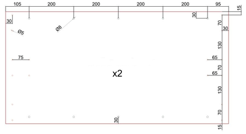
|
| Figure 77: Central modules |
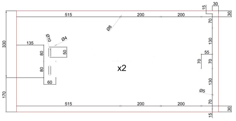
|
| Figure 78: Lateral modules |
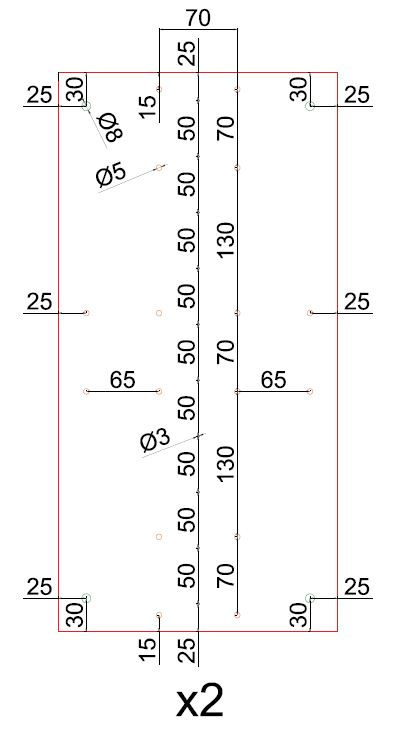
|
| Figure 79: Plates for the central union |
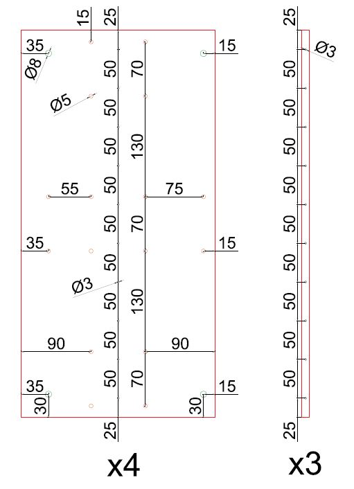
|
| Figure 80: Plates for the lateral unions and drills in the hollow tubes |
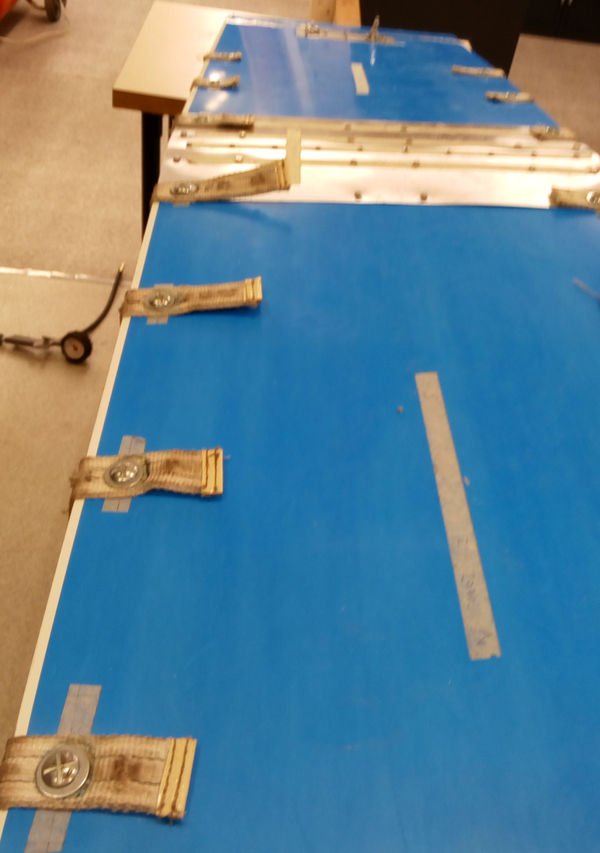
|
| Figure 81: Detail on bolts and unions |
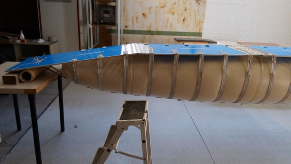
|
| Figure 82: Support and shackles in the prototype |
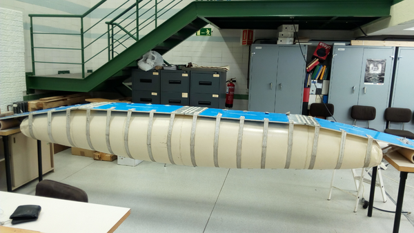
|
| Figure 83: Unloaded configuration of the prototype |
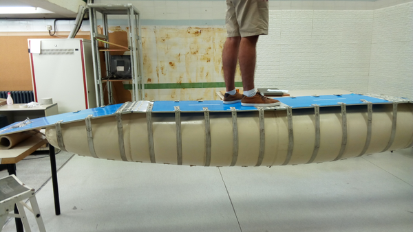
|
| Figure 84: Loaded configuration of the prototype |
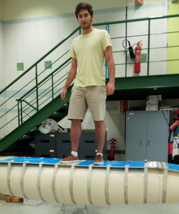
|
| Figure 85: Serviceability conditions |
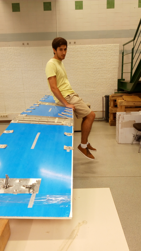
|
| Figure 86: Torsion effect on the prototype |
|
| Figure 87: Local deformations on the contact walkway-loading belt |
|
| Figure 88: Reinforced contact areas |
BIBLIOGRAPHY
[1] Cremers, J.M. (2011) "Energy saving design of membrane building envelopes". Structural membranes 2011. Springer International Publishing 147–157
[2] Strickland, M.H. (2010) "Roman building materials, construction methods, and architechture: the identity of an empire"
[3] Berger, H. (1996) "Light structures - structures of light : The art and engineering of tensile architecture". Birkhäuser 186
[4] Luchsinger, R.H. and Galliot, C. (2012) "Structural behavior of symmetric spindle-shaped Tensairity girders", Volume 139. Journal of Structural Engineering 2 169–179
[5] Tam, P.W.M. (1998) "Application of inflatable dam technology - problems and countermeasures", Volume 25. Canadian Journal of Civil Engineers 2 383–388
[6] Jensen, U. J. (1993) "Patent WO 1993021389 A1: Inflatable bridge, especially for rescue purposes, and hose for stiffening the bridge"
[7] Army, Headquarters department of the USA. (1986) "Bayley bridge"
[8] Estruch Tena, C. (2016) "Nuevo concepto de puente de vigas hinchables ligero, modular y portátil". Universitat Politecnica de Catalunya
[9] Griffith, S. and Lynn, P.S. (2014) "Patent US 8640386 B1: Stiffening of an air beam"
[10] Pedretti, M. and Luscher, R. (2007) "Tensairity-Patent – Eine pneumatische Tenso-Struktur", Volume 76. Stahlbau 314–319
[11] Skelton, R.E. and Adhikari, R. and Pinaud, J.P. and Chan, W. and Helton, J.W. (2001) "An introduction to the mechanics of tensegrity structures", Volume 5. Proceedings of the 40th IEEE Conference on Decision and Control 4254–4259
[12] Llorens, J. (2011) "Zoomorphism and bio-architecture: between the formal analogy and the aplication of nature's principles". Structural Membranes 2011 17–27
[13] Luchsinger, R.H. and Pedretti, A. and Pedretti, M. and Steingruber, P. (2004) "The new structural concept Tensairity: Basic principles". Progress in Structural Engineering 1–5
[14] Luchsinger, R.H. and Pedretti, M. and Reinhard, A. (2004) "Pressure induced stability: from pneumatic structures to Tensairity", Volume 1. Journal of Bionics Engineering 3 141–148
[15] Luchsinger, R.H. and Pedretti, A. (2004) "Light weight structures with Tensairity". Shell and Spacial Structures from models to realization 80–81
[16] Pedretti, A. and Steingruber, P. and Pedretti, M. and Luchsinger, R.H. (2004) "The new structural concept Tensairity: FE-modeling and applications", Volume 21. International Journal of Space Structures 3 119–130
[17] Luchsinger, R.H. and Crettol, R. (2006) "Experimental and numerical study of spindle shaped Tensairity girders", Volume 21. International journal of space structures 3 119–130
[18] Plagianakos, T. and Teutsch, U. and Crettol, R. and Luchsinger, R.H. (2008) "Static response of a spindle-shaped Tensairity column to axial compression". EMPA Activities 2008-2009 31
[19] Luchsinger, R.H. and Teutsch, U. (2009) "An analytical model for Tensairity girders". Proceedings of the International Association for Shell and Spatial Structures (IASS) Symposium October 2771–2779
[20] Luchsinger, R.H. and Sydow, A. and Crettol, R. (2011) "Structural behavior of asymmetric spindle-shaped Tensairity girders under bending loads", Volume 49. Thin-Walled Structures 9 1042–1053
[21] Laet, L. De and Mollaert, M. and Luchsinger, R.H. and Temmerman, N. De. (2010) "Mechanisms for deployable tensairity structures". Journal of the International Association for Shell and Spatial Structures January
[22] Laet, L. De and Luchsinger, R.H. and Mollaert, M. and Temmerman, N. De. (2009) "Deployable Tensairity structures", Volume 50. Journal of the International Association for Shell and Spatial Structures 2 121–128
[23] Wilkins, T. (2015) "Subject: Prospect for European guidance for the Structural Design of Tensile Membrane Structures" October
[24] Kumar, R. and Kumar, K. (2014) "Design and optimization of portable foot bridge", Volume 97. Procedia Engineering 1041–1048
[25] LLC, Matweb. (2017) "BASF Styrodur 4000 CS Extruded Rigid Polystyrene Foam (Europe)"
[26] de Vries, D.V.W.M. (2009) "Characterization of polymeric foams". Eindhoven University of Technology July
[27] GoodFellow. (2017) "Polymer - Mechanical Properties"
[28] Teijinconex. (2017) "Mechanical properties"
[29] Blum, R. and Bögner, H. and Némoz, G. (2017) "Material properties and testing"
[30] Azart. (2017) "PVC Inflatable Bridges"
[31] Convertex. (2017) "Convertex Rescue Bridge"
[32] PKI. (2017) "Rescue Bridge"
[33] Trenberth, K.E. (2006) "The Impact of Climate Change and Variability on Heavy Precipitation, Floods, and Droughts". Encyclopedia of Hydrological Sciences. John Wiley & Sons, Ltd
[34] Farrell, K. (2017) "The Rapid Urban Growth Triad: A New Conceptual Framework for Examining the Urban Transition in Developing Countries", Volume 9. Sustainability 8 1407
[35] Christensen, J.H. and Christensen, O.B. (2003) "Climate modelling: Severe summertime flooding in Europe", Volume 421. Nature 6925 805–806
[36] Douglas, Ian and Alam, Kurshid and Maghenda, Maryanne and Mcdonnell, Yasmin and Mclean, Louise and Campbell, Jack. (2008) "Unjust waters: climate change, flooding and the urban poor in Africa", Volume 20. SAGE Publications Ltd. Environment and Urbanization 1 187–205
[37] Crunch, C. (2017) "Disaster data: A balanced perspective". Centre for Research on the Epidemiology of Disasters 48
[38] Wahlstrom, M. and Guha-Sapir, D. (2015) "The human cost of weather-related disasters 1995-2015". UNISDR Publications 30
[39] Fire Brigades Union. (2015) "December 2015 floo" December
Document information
Published on 01/01/2017
Licence: CC BY-NC-SA license
Share this document
Keywords
claim authorship
Are you one of the authors of this document?
